Viega ProPress User manual

Installation Manual
Viega ProPress®

Table of Contents
2 of 38IM-PP 724607 1218 ProPress
Table of Contents
1 About this Document ______________________________________ 5
1.1 Disclaimer ____________________________________________ 5
1.2 Symbols Used _________________________________________ 5
2 Product Information _______________________________________ 6
2.1 ProPress Systems ______________________________________ 6
2.2 Safety ________________________________________________ 6
2.2.1 Drinking Water Installation ________________________ 6
2.3 Areas of Use __________________________________________ 7
2.3.1 Commercial and Residential ______________________ 8
2.3.2 Industrial and Plant Operations ____________________ 8
2.3.3 Fire Protection Systems __________________________ 8
2.3.4 Design Services _________________________________ 8
2.4 Product Description ____________________________________ 8
2.4.1 Overview _______________________________________ 8
2.4.2 Listings and Certications_________________________ 9
2.4.3 Codes and Standards ____________________________ 9
2.4.4 Copper Tubing _________________________________ 10
2.4.5 Press Fittings __________________________________ 10
2.4.5.1 Viega ProPress Fittings ___________________ 10
2.4.5.2 Viega ProPress XL-C Fittings ______________ 10
2.4.5.3 EPDM Sealing Element ___________________ 10
2.4.5.4 Cylindrical Guides _______________________ 11
2.4.5.5 Fitting Markings _________________________ 11
2.4.5.6 Viega Smart Connect Technology __________ 12
2.5 General Installation Requirements ________________________ 12
2.5.1 Required Tools _________________________________ 12
2.5.2 Expansion _____________________________________ 13
2.5.3 Electrical Bonding ______________________________ 13
2.5.4 Exposure to Freezing Temperatures _______________ 14
2.5.5 Underground Installations ________________________ 14
2.5.6 Corrosion Protection ____________________________ 14
2.5.6.1 Mixed Installations _______________________ 14
2.5.7 Pressure Surges _______________________________ 15
2.5.8 Rotating a Pressed Fitting _______________________ 15
2.5.9 Deection _____________________________________ 15
2.5.9.1 Controlling Deection ____________________ 16
3 Handling Instructions _____________________________________ 17
3.1 Transport ____________________________________________ 17
3.2 Storage ______________________________________________ 17

Table of Contents
3 of 38IM-PP 724607 1218 ProPress
4 Installation Instructions ___________________________________ 18
4.1 Check System Components ____________________________ 18
4.1.1 Replacing the Sealing Element ___________________ 18
4.2 Installing and Mounting the Tube ________________________ 19
4.2.1 Pipe Hangers and Supports ______________________ 19
4.3 Space Requirements and Intervals _______________________ 19
4.3.1 Transition Fittings _______________________________ 20
4.3.1.1 Threaded Connections ___________________ 20
4.3.1.2 Flange Connections ______________________ 20
4.3.2 Minimum Distance between Fittings _______________ 20
4.3.3 ProPress Jaws Clearance Requirements ___________ 20
4.3.4 ProPress Rings Clearance Requirements ___________ 22
4.4 Soldering or Brazing ___________________________________ 24
4.4.1 Using ProPress Near Existing Fittings ______________ 24
4.4.2 Soldering or Brazing Near Existing ProPress Fitting __ 24
4.5 Welding _____________________________________________ 25
4.5.1 Welding Adjacent to a Fitting _____________________ 25
4.5.2 Welding In Line with a Fitting _____________________ 25
4.6 Cutting the Tube ______________________________________ 26
4.7 Deburring the Tube ____________________________________ 26
4.8 Pressing the Fitting ____________________________________ 27
4.8.1 Viega ProPress Installation _______________________ 27
4.8.2 Viega ProPress XL-C Installation __________________ 30
4.9 Pressure Testing ______________________________________ 33
4.10 Disposal _____________________________________________ 33
5 Limited Warranty _________________________________________ 34
5.1 Limited Warranty for ProPress Fittings and Valves __________ 34
5.2 Limited Warranty for Industrial Application _________________ 35
5.3 Limited Warranty for Marine Application ___________________ 36

Table of Contents
4 of 38IM-PP 724607 1218 ProPress
List of Tables
Table 1 Fluids and water approved for use with ProPress systems ____ 7
Table 2 Gases approved for use with ProPress systems ____________ 7
Table 3 Minimum distance between press ttings _________________ 20
Table 4 ProPress standard jaws clearance requirements ___________ 21
Table 5 ProPress standard jaws clearance requirements between
tube, wall, and oor ___________________________________ 21
Table 6 ProPress compact jaws clearance requirements ___________ 21
Table 7 ProPress compact jaws clearance requirements between
tube, wall, and oor ___________________________________ 21
Table 8 ProPress rings dimensions _____________________________ 22
Table 9 ProPress rings with V1 Actuator clearance requirements ____ 22
Table 10 ProPress rings with V2 Actuator clearance requirements ____ 22
Table 11 ProPress rings with V1 Actuator clearance requirements
between tube, wall, and oor ___________________________ 22
Table 12 ProPress rings with V2 Actuator clearance requirements
between tube, wall, and oor ___________________________ 23
Table 13 ProPress rings with C1 Actuator clearance requirements
between tube, wall, and oor ___________________________ 23
Table 14 ProPress XL-C rings dimensions ________________________ 23
Table 15 ProPress XL-C rings clearance requirements ______________ 23
Table 16 ProPress XL-C rings clearance requirements between tube,
wall, and oor ________________________________________ 23
Table 17 Minimum distance between existing soldered or brazed tting
and ProPress tting ___________________________________ 24
Table 18 Minimum distance between existing ProPress tting and soldered
or brazed tting _______________________________________ 25
Table 19 Minimum insertion depths for ProPress ___________________ 27
Table 20 Insertion depths for ProPress non-stop couplings __________ 28
Table 21 Insertion depths for ProPress extended non-stop couplings _ 28
Table 22 Minimum insertion depths ProPress XL-C _________________ 31
Table 23 Insertion depths for ProPress XL-C non-stop couplings _____ 31

About this Document
5 of 38
IM-PP 724607 1218 ProPress
1 About this Document
DANGER!
This symbol warns of possible life-threatening injury.
WARNING!
This symbol warns of possible serious injury.
CAUTION!
This symbol warns of possible injury.
NOTICE!
This symbol warns of possible damage to property.
Notes give additional helpful tips.
1.1 Disclaimer
1.2 Symbols Used
The following symbols may be used within this document:
Viega products are designed to be installed by licensed and
trained plumbing and mechanical professionals who are
familiar with Viega products and their installation. Installation
by non-professionals may void Viega LLC’s warranty.
This document is subject to updates. For the most current
Viega technical literature please visit www.viega.us.

Product Information
6 of 38
IM-PP 724607 1218 ProPress
Please read and understand the instructions before beginning installation
to eliminate safety concerns and reduce risks associated with use and
handling of Viega products.
Viega ProPress systems are state-of-the-art press tting systems
that provide economical and reliable installations for the commercial,
industrial, and residential markets.
Viega ProPress are copper and zero lead bronze ttings and valves in
copper tube size (CTS) ranging from ½ inch to 2 inches for ProPress
ttings and 2½ inches to 4 inches for ProPress XL-C® (Copper) ttings.
The ttings require no soldering or brazing and are installed with electro-
hydraulic press tools (battery-powered or corded press tools).
The ttings feature a green dot representing Smart Connect® technology
with an EPDM sealing element suitable for many applications. Viega’s
unique, patented Smart Connect technology helps installers ensure that
they have pressed all connections.
2 Product Information
2.1 ProPress Systems
2.2 Safety
2.2.1 Drinking Water Installation
Standard engineering practices must be observed for planning,
installation, operation, and maintenance of drinking water installations.
Only EPDM sealing elements are approved in drinking water installations.
The use of other sealing elements is not permitted.

Product Information
7 of 38
IM-PP 724607 1218 ProPress
The use of the system for applications other than those
listed or outside of these parameters must be approved by
the Viega Technical Services Department.
2.3 Areas of Use
Type of Service Comments Pressure Temperature
Hot and cold potable water 200 psi 32° to 250°F
Rainwater / gray water 200 psi 32° to 250°F
Fire sprinklers Listed with UL and FM 175 psi 32° to 250°F
Chilled water Ethylene glycol /
propylene glycol 200 psi 0° to 250°F
Hydronic heating Ethylene glycol /
propylene glycol 200 psi 0° to 250°F
Cooling water Up to 50% ethylene
glycol or propylene
glycol solution
200 psi 0° to 250°F
Low-pressure steam ≤ 15 psi max 250°F
Ethanol Pure grain alcohol 200 psi Ambient
Table 1: Fluids and water approved for use with ProPress systems
Type of Service Comments Pressure Temperature
Compressed air Oil concentrate
< 25 mg/m3200 psi 0° to 140˚F
Oxygen - O2 (nonmedical) Keep oil and fat free
/ non-liquid O2
140 psi 0° to 140˚F
Nitrogen - N2200 psi 0° to 140˚F
Carbon dioxide - CO2200 psi 0° to 140˚F
Argon Welding use 200 psi 0° to 140˚F
Hydrogen - H2125 psi 0˚ to 140˚F
Vacuum 29.2" of Hg 0° to 160˚F
Table 2: Gases approved for use with ProPress systems
It is recommended that all systems be clearly labeled with the uid or gas
being conveyed. In the absence of local requirements, systems should be
identied in accordance with ANSI/ASME A13.1.

Product Information
8 of 38
IM-PP 724607 1218 ProPress
2.3.1 Commercial and Residential
ProPress systems are approved for numerous applications in commercial
and residential markets including potable water. “Zero Lead” identies
products meeting the lead-free requirements of NSF 61 through testing
under NSF/ANSI 372 (0.25% or less maximum weighted average lead
content).
2.3.2 Industrial and Plant Operations
ProPress systems are also suitable for use in industrial and plant
processes. Primary areas of application include:
■ Utility systems
■ Process piping
■ Cooling water
■ Potable water
■ Fire sprinkler systems
2.3.3 Fire Protection Systems
The system components may be installed in NFPA 13, 13R, and 13D
re sprinkler systems. They are certied for use in “wet” and “dry” re
protection systems in accordance with UL and FM certications:
■ UL/ANSI 213: Standard for Rubber Gasketed Fittings for Fire-
Protection Services.
■ ULC ORD-C213: Canadian Standard for Rubber Gasketed Fittings for
Fire-Protection Services.
■ FM Class 1920: Pipe Couplings and Fittings for Aboveground Fire
Protection Systems.
2.3.4 Design Services
Consult Viega’s Technical Services Department for information on applications
not listed or applications outside listed temperature and pressure ranges.
■ Viega Technical Services Department: T[email protected]
■ Design Service: For more information on re protection system design,
radiant system design, and plumbing design services: [email protected]
2.4 Product Description
2.4.1 Overview
ProPress systems consists of copper and Zero Lead bronze press ttings
for copper tubes and the corresponding press tools.

Product Information
9 of 38
IM-PP 724607 1218 ProPress
2.4.2 Listings and Certications
The ttings have the following listings and certications:
■ ABS: American Bureau of Shipping Type Approval
■ ASME B16.51: Copper and Copper Alloy Press-Connect Pressure Fittings
■ ASME B31.1: Power Piping
■ ASME B31.3: Process Piping
■ ASME B31.9: Building Service Piping
■ BV: Bureau Veritas Type Approval
■ Canadian Registration Number (CRN): 0A14541.5 A/B/C
■ CSA Low Lead Content
■ DNV GL: Det Norske Veritas Germanischer Lloyd Type Approval
■ FM Class 1920: Pipe Couplings and Fittings for Aboveground Fire
Protection Systems
■ IAPMO PS-117: Press and Nail Connections
■ ICC-ES LC1002: Copper and Copper Alloy Press-Connect Pressure Fittings
■ LR: Lloyd’s Register Type Approval
■ NFPA 13: Standard for the Installation of Sprinkler Systems
■ NFPA 13D: Standard for the Installation of Sprinkler Systems in One-
and Two-Family Dwellings and Manufactured Homes
■ NFPA 13R: Standard for the Installation of Sprinkler Systems in Low-
Rise Residential Occupancies
■ NKK: Nippon Kaija Kyokai Type Approval
■ NSF/ANSI 61: Drinking Water System Components – Health Eects
■ NSF/ANSI 372: Drinking Water System Components – Lead Content
■ UL/ANSI 213: Standard for Rubber Gasketed Fittings for Fire-
Protection Service
■ ULC/ANSI ORD-C213: Canadian Standard for Rubber Gasketed
Fittings for Fire-Protection Service
2.4.3 Codes and Standards
ProPress ttings comply with the following codes and standards:
■ ASME B31: Code for Pressure Piping
■ ASTM B88: Standard Specication for Seamless Copper Water Tube
■ IAPMO California Plumbing Code (CPC)
■ IAPMO National Standard Plumbing Code (NSPC)
■ IAPMO Uniform Mechanical Code (UMC)
■ IAPMO Uniform Plumbing Code (UPC)
■ ICC International Mechanical Code (IMC)
■ ICC International Plumbing Code (IPC)
■ ICC International Residential Code (IRC)
■ National Building Code of Canada (NBCC)
■ National Plumbing Code of Canada (NPCC)
It is the responsibility of the installer or any other parties
to adhere to all applicable local rules and regulations
governing the nature of the installation.

Product Information
10 of 38
IM-PP 724607 1218 ProPress
2.4.4 Press Fittings
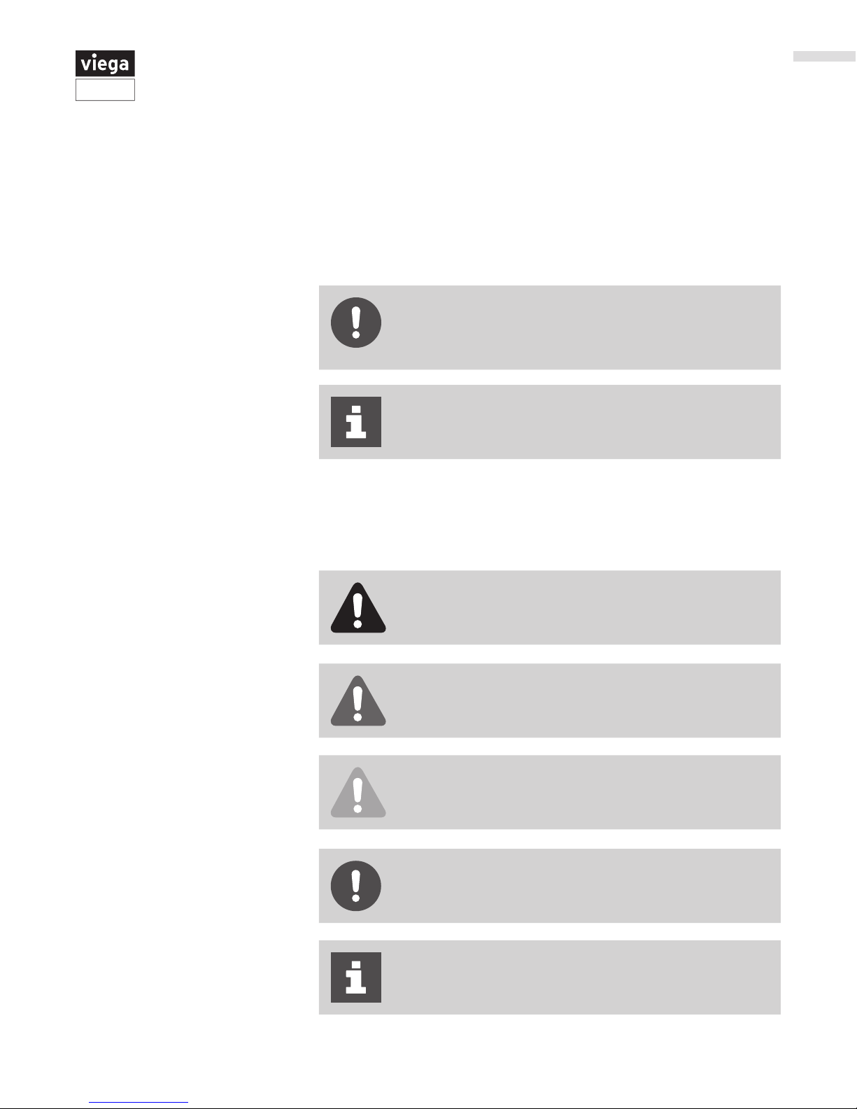
2.4.4.1 Viega ProPress Fittings
1 Each tting contains an application specic sealing element. A green
dot on a Viega ProPress tting indicates the presence of Smart
Connect technology and an EPDM sealing element.
2 Viega’s distinctive hexagonal pressing pattern bonds tting and tube
and provides the mechanical strength for the connection.
3 Color coded dots indicate the presence of Viega’s unique, patented
Smart Connect technology which helps installers ensure that they
have pressed all connections.
4 Cylindrical guides ensure the proper insertion of the tube and protects
the sealing element.
2.4.4.2 Viega ProPress XL-C Fittings
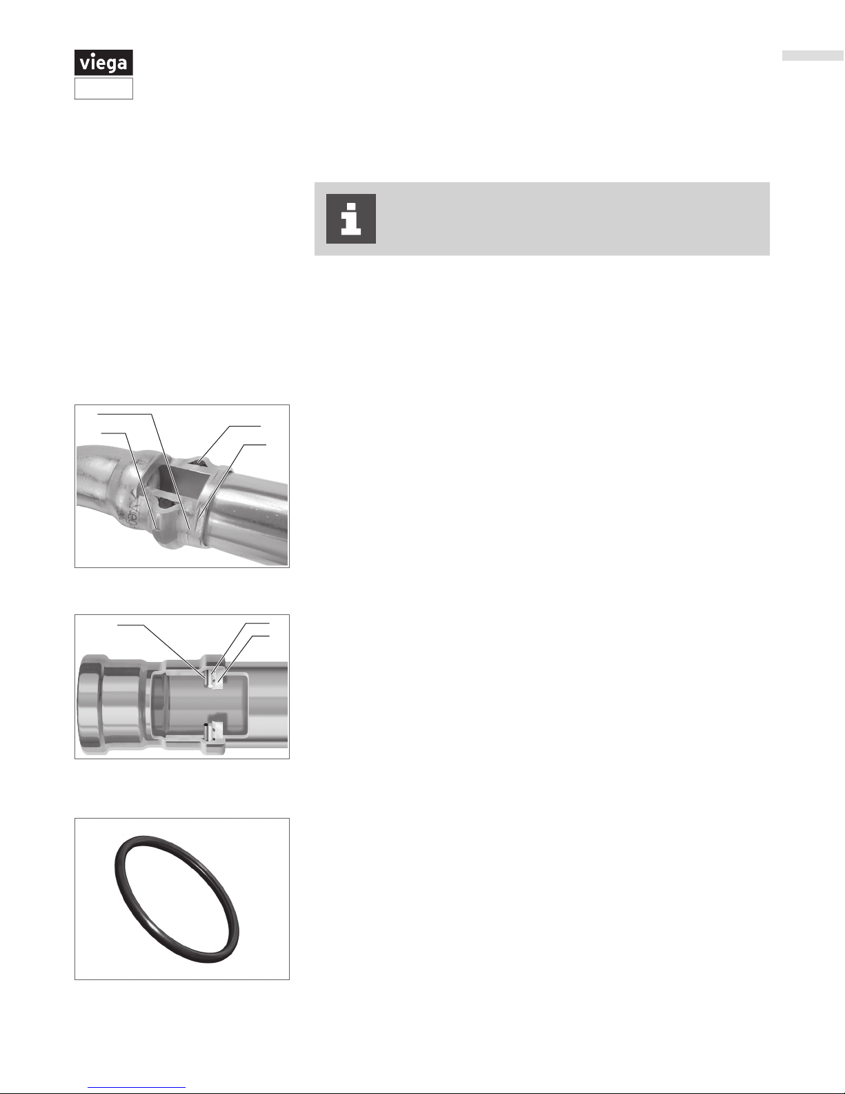
Viega ProPress ttings are manufactured with a high-quality, shiny black
EPDM (Ethylene Propylene Diene Monomer) sealing element installed at
the factory. The molded sealing lips also seal tube surfaces with slightly
uneven surfaces. Sealing elements are inserted into the tting using a H1
food grade lubricant registered with NSF and the USDA, and is approved
for use under FDA 21 CFR.
The EPDM sealing element possesses excellent resistance to aging,
ozone, sunlight, weathering, environmental inuences, and most alkaline
solutions and chemicals used in a broad range of applications.
The operating temperature of the EPDM sealing element is 0° to 250°F
(-18° to 120°C).
2.4.4.3 EPDM Sealing Element
1 The 420 stainless steel grip ring's teeth cut into the tube and lock the
tting securely in place.
2 A PBT (Polybutylene Terephthalate) separator ring protects the sealing
element from damage by creating a positive physical separation during
installation and later during pressing.
3 The EPDM sealing element ensures water-tight or air-tight connections.
ProPress XL-C ttings are designed to be pressed with ProPress XL-C press
rings and V2 actuator to produce a non-detachable, secure connection.
2.4.5 Copper Tubing
Copper and copper alloy ttings are compatible with ½ inch to 1¼ inches soft
copper tubing and ½ inch to 4 inches hard copper tubing types K, L, and M. All
copper tubing that is to be used must comply with ASTM B88 standards.
Copper tubing must be free of surface imperfections,
including metal stamped print lines, before a ProPress
tting is installed.

Product Information
11 of 38
IM-PP 724607 1218 ProPress
Fittings are pressed before, after, and on top of the sealing element in a
single step. This distinctive hexagonal pressing pattern bonds tting and
tube.
All Viega ttings are designed with cylindrical guides to keep the tube
straight and protect the sealing element during assembly.
Fittings that do not have cylindrical guides risk making an unsecured
connection. Without the guides, installers may damage the sealing
element.
2.4.5.1 Cylindrical Guides
2.4.5.2 Fitting Markings
Each ProPress tting is marked with the following:
■ Green dot: EPDM sealing element and Smart Connect technology
■ Size of tting
■ Manufacturer name
■ Manufacturer date code
■ CSA®
■ NSF®-61-372
■ UPC®
■ UL®
■ FM

Product Information
12 of 38
IM-PP 724607 1218 ProPress
2.4.5.3 Viega Smart Connect Technology
Viega Smart Connect technology provides the installer quick and easy
identication of an unpressed tting during a leak test. When the tting
is pressed, a secure, non-detachable, mechanical connection is created.
Smart Connect technology provides the installer with an easy way to see
connections that have not been pressed before putting the system into
operation.
Testing for leaks using Viega Smart Connect is not a
replacement for testing requirements of local codes and
standards. If testing with compressed air, it is necessary to
use an approved leak-detect solution.
3Viega ProPress
connections are
fast, flameless, and
reliable.
1Identify an unpressed
connection during
pressure testing
when water flows past the
sealing element.
2
Upon identification,
use the press tool
to press the fitting,
making a secure leak-
proof connection.
2.5 General Installation Requirements
The Viega ProPress tting system must be installed while considering the
following general industry requirements.
2.5.1 Required Tools
The following tools are required for making a press connection:
■ Pipe cutter or a ne-toothed hacksaw
■ Deburring tool
■ Marker for marking insertion depth on tube
■ Press machine with constant pressing force
■ Press jaw or press ring with corresponding actuator suitable for the
tube diameter and with the proper prole
Viega recommends RIDGID press tools, Viega ProPress jaws and ring
sets, and RIDGID pipe preparation tools manufactured and sold by the
Ridge Tool Company for use with Viega systems.
Improper Tool/Material Damage
Only use press jaws and rings that are designed for use
with ProPress ttings.

Product Information
13 of 38
IM-PP 724607 1218 ProPress
2.5.2 Expansion
Thermal expansion in installed systems generates stress on tubing and
appliance connectors. Compensation must be allowed for expansion
and contraction that may occur within the tubing. Expansion joints or
mechanical expansion compensators may be used to alleviate these
stresses. ProPress systems do not require any additional protection when
compared to a soldered system.
The following methods are eective:
■ Fixed and sliding hangers
■ Expansion equalization joints (expansion bends)
■ Expansion compensators
2.5.3 Electrical Bonding
When properly installed, ProPress ttings comply with Section 1211.15
Electrical Bonding and Grounding of the Uniform Plumbing Code and
Section 310 of the International Fuel Gas Code.
The mechanical press provides continuous metal-to-metal contact
between tting and tube. The press ensures the continuity of the bonding
through this contact.
A qualied electrician is responsible for ensuring electrical
bonding is tested and secured.
DANGER!
Electric Shock
An electric shock can cause burns, serious injury, and
even death.
■ Because all metallic tubing can conduct electricity,
unintentional contact with a live wire can lead to
the entire system and components connected to it
to become energized. Metal piping is not meant to
conduct electricity.
■ A properly bonded system creates a safe path for
electricity to travel so that the system can't be energized.
■ An unbonded or improperly bonded system can be a
shock hazard.
■ Always ensure bonding is in accordance with local codes.

Product Information
14 of 38
IM-PP 724607 1218 ProPress
2.5.4 Exposure to Freezing Temperatures
Viega ProPress systems with EPDM sealing elements can be installed
in ambient temperatures down to 0° F. Tubing exposed to freezing
temperatures must be protected per acceptable engineering practices,
codes, and as required by local code.
2.5.5 Underground Installations
Viega ProPress tting systems with copper tubing are approved for
underground installations. However, installations must meet all state and
local codes, including those for underground. Proper authorization must
be obtained prior to installation from the Authority Having Jurisdiction.
2.5.6 Corrosion Protection
Viega ProPress ttings exposed to corrosive action, such as soil
conditions or moisture, must be protected in an approved manner in
accordance with NFPA 54 Section 404.8, NACE Standard RP0169-2002
Section 5, 2009 UPC Chapter 6 Section 609.3.1, 2009 UMC Chapter
13 Section 1312.1.3, or satisfying local code requirements. In addition,
systems should be properly sized to minimize the risk of erosion corrosion
resulting from excessive velocities.
2.5.6.1 Mixed Installations
■ In water installations, mixed metal systems can have a detrimental
eect on each other and cause corrosion.
■ Copper tubing should not be installed directly upstream from
galvanized steel pipe.
■ Dielectric unions should be used when connecting copper to steel or
galvanized steel pipe.
■ Care should be taken to select hangers of suitable material that are
galvanically compatible with the tubing.
Above ground copper tubing and ttings do not normally require external
corrosion protection with the following exceptions:
■ Contact with aggressive building materials such as nitrite or materials
containing ammonium.
■ In aggressive environments.
Please contact the Viega Technical Services Department for questions on
this subject.
The ow rule must be observed in all mixed installations
with tubing made of copper and pipes made of galvanized
steel.

Product Information
15 of 38
IM-PP 724607 1218 ProPress
2.5.7 Pressure Surges
■ Pressure surges or transients from fast-acting valves, pump surges,
and other sources that result in water hammer may cause damage to
many system components, including press ttings.
■ When fast-acting valves and/or pumps are incorporated into a system,
the designer and installer should isolate press ttings from sharp
pressure surges.
2.5.8 Rotating a Pressed Fitting
Once a ProPress tting has been pressed, it can be rotated (not by hand),
but once rotated more than ve degrees, the tting should be repressed
to restore resistance to rotational movement.
If the tting is re-pressed, care should be taken to align the at sides on
the jaw with those on the tting.
2.5.9 Deection
The pressing process can cause deection (angular misalignment) to
occur. When pressing Viega ProPress ttings in a system, the deformation
of the tting is constant. This allows for a consistent leak-free joint every
time and is a result of the pressing technique.
Deection occurs in the same way for every tting. The tting being
pressed will move in the direction of the jaw or ring opening.
■ Since the tting will deect toward the opening of the jaw or ring, the
tube end will deect in the opposite direction.
■ By counteracting the tting movement, one can minimize the
deection of the tting and ultimately the tube.
■ When using strut and clamps, deection is minimized and nearly
eliminated depending on clamp spacing.
■ ProPress ttings should be isolated or separated by
sucient distance from pumps, fast-acting valves, and
other sources of pressure transients.
■ The maximum operating pressure in a ProPress system
is 200 psi, which applies to general operation as well as
pressure transients.
■ Good engineering practices should be used to design
the system in a way that minimizes sharp pressure
surges.

Product Information
16 of 38
IM-PP 724607 1218 ProPress
■ As long as the tube is properly prepped and marked
and the tting is installed according to Viega’s ProPress
Product Instructions, if there is any deection present
after the installation of the tting, the connection is
still acceptable and meets Viega’s manufacturing
specications for proper installation and warranty.
■ Deection of a press connection has no eect on the
integrity of the system, and it can be pressure tested in
accordance with the ProPress Product Instructions.
Push-pull method
▶ Rings = Push on press tool.
▶ Jaws = Pull on press tool.
The press tool can be feathered using the trigger as needed to apply
pulling or pushing force to control deection.
2.5.9.1 Controlling Deection
Deection while pressing can be minimized by utilizing the following
installation practices.
Alternate sides for presses
▶ Press one end of tting.
▶ Make second press on other end of tting from the opposite side.
Site conditions permitting.
Re-Press
▶ Press the tting, once on each side (that is, re-press the tting a
second time on the opposite side). Pressing the same connection
from the opposite side will usually straighten misalignment between
the tube and tting.
■ When pressing overhead piping, it may be inconvenient to alternate
sides for each press.
■ The natural weight of the piping plus pressing on opposite sides at a
45 degree angle should adequately eliminate deection.
■ This technique can also be used for any horizontal piping and also
when working above the piping.

Handling Instructions
17 of 38
IM-PP 724607 1218 ProPress
All Viega ProPress components and associated tubing shall be free from
dirt, debris, or items that may interfere with the sealing element and the
press connection. Viega ProPress sealing elements, separator rings, and
grip rings are to be visually inspected prior to installation to ensure the
seal is intact and properly located within the tting.
3 Handling Instructions
3.1 Transport
When transporting ttings:
■ Do not pull or drag the ttings or system components along other
surfaces.
■ Secure ttings, tubing, and system components during transportation
to keep them from shifting.
■ Do not damage the protective cap on components or tube ends.
■ Do not remove protective caps until immediately before installing.
3.2 Storage
When storing materials:
■ Store ttings, tubing, and system components in a clean and dry
place.
■ Do not store components directly on the oor.
■ Provide at least three points of support for the storage of tubing.
■ Where possible, store dierent sizes separately.
■ Store small sizes on top of larger sizes if separate storage is not
possible.
■ Store ttings, tubing, and system components of dierent materials
separately to prevent contact corrosion.

Installation Instructions
18 of 38
IM-PP 724607 1218 ProPress
System components may, in some cases, become damaged through
transportation and storage.
■ Check all parts.
■ Replace damaged components.
■ Do not repair damaged components.
■ Contaminated components may not be installed.
4 Installation Instructions
4.1 Check System Components
4.1.1 Replacing the Sealing Element
Damage to the Sealing Element
If damage to the sealing element, separator ring, or grip ring is
discovered, contact a Viega District Manager for assistance.
Do not use metallic pointed or sharp objects during
removal because they could damage the sealing element
and/or bead. Try using a toothpick instead.
If the sealing element in the tting is obviously damaged, it should be
exchanged for a Viega replacement sealing element.
▶ Insert new, undamaged sealing element into the bead.
▶ Check to make sure that the whole sealing element is in the bead.
▶ Remove the sealing element from the bead.

Installation Instructions
19 of 38
IM-PP 724607 1218 ProPress
4.2 Installing and Mounting the Tube
Observe the general rules of hanging and mounting:
■ Fixed tubing should not be used as support for other tubing and
components.
■ Do not use pipe hooks.
■ Observe distance between ttings and mounting points.
■ Observe the expansion direction – plan xed and sliding mounts.
4.2.1 Pipe Hangers and Supports
Tubing supports perform two functions:
■ To provide support for the tubing.
■ To guide the tube during thermal expansion and contraction.
Fittings must not be used as support
■ System malfunction may result from additional stress and
strain put on the tting.
■ At no point in the system should a tting be the sole means
of support. For example, when installing a tee, both the
branch and the trunk must be properly supported.
Industry standard practices and guidelines shall be used for tube layout
and support. Viega press connections require no special consideration for
support.
Hangers and supports must conform to the local code requirements. In
the absence of local code requirements, hangers and supports should
conform to ANSI/MSS SP 58 Pipe Hangers and Supports - Materials,
Design, Manufacture, Selection, Application and Installation.
4.3 Space Requirements and Intervals
Not enough space
The connection may leak and/or ring/press gun may not t
around the tting.
■ Adhere to minimum space requirements.
■ Make sure that the space required for pressing tools is
available if ttings will be pressed immediately upstream or
downstream from wall or ceiling penetrations.
■ Take the minimum required distances into consideration
during the planning phase of the project whenever possible.

Installation Instructions
20 of 38
IM-PP 724607 1218 ProPress
4.3.1 Transition Fittings
4.3.1.1 Threaded Connections
The Viega ProPress systems can be joined with o-the-shelf threaded
ttings made of non-ferrous metals.
In this regard:
■ The threaded connection is made rst.
■ The press connection is made second.
This process avoids unnecessary torsion on the press tting.
4.3.1.2 Flange Connections
When using Viega anges, bolt the ange end in place prior to pressing the
tting to the tube.
4.3.2 Minimum Distance between Fittings
To ensure a correct press, a minimum distance between press ttings must
be maintained. Failure to provide this distance may result in an improper seal.
For installations where the minimum distance is zero, it is particularly
important to ensure the correct insertion depth of the tube into each tting.
Tube Diameter (inches) A minimum (inches) A minimum (mm)
½
0 0¾
1
1¼ 7
/
16 10
1½ ⅝ 15
2 ¾ 20
2½
⅝ 153
4
Table 3: Minimum distance between press ttings
minimum
distance
4.3.3 ProPress Jaws Clearance Requirements
The minimum distance between tube, or the tube and the wall/ceiling
construction, must be taken into consideration in the planning phase for a
problem free work process. The following illustrate the clearance requirements
for the jaws and ttings and the procedure for pressing ttings in tight quarters.
Tubing installed too closely together
Connection may leak
■ Adhere to minimum intervals between ttings.
■ Insert tube to full insertion depth before pressing.
Table of contents
Other Viega Power Tools manuals

Viega
Viega MegaPress XL PressBooster 4896.2XL User manual

Viega
Viega Eco Plus User manual

Viega
Viega Pressgun 6 User manual

Viega
Viega 4296.2XL User manual

Viega
Viega Pressgun Press Booster PT2 User manual

Viega
Viega Pressgun 6 User manual

Viega
Viega MegaPress XL User manual

Viega
Viega Picco 6 User manual

Viega
Viega Pressgun 6B User manual

Viega
Viega Picco 6 User manual
Popular Power Tools manuals by other brands

Seymour
Seymour Z-500 Product information sheet

SCHUNK
SCHUNK RST-P 060 Assembly and operating manual

Evolution
Evolution Rage 7 Original instructions

Parkside
Parkside 406362 2207 Translation of the original instructions

Precision matthews
Precision matthews PM-739M manual

Bosch
Bosch PSR 12-2 Original instructions