vienybe SIRIJUS 20 Owner's manual

Technical Datasheet, installation and Operation Manual 3
SOLID FUEL BOILERS
SIRIJUS 20
SIRIJUS 30
LST EN 303-5 GOST 20548
ENG
Sirijus 20, 30 (13.05) V1 LT

Sirijus 20, 30 Sirijus 20, 30
Sirijus 20, 30 (13.05) V1 LT Sirijus 20, 30 (13.05) V1 LT
13. CERTIFICATE OF ACCEPTANCE
Heating boiler “SIRIJUS -““,
Serial No. ____________________
Meets the requirements of LST EN 303-5 and GOST 20548 and is suitable for use.
Date of manufacture ________________________
TKS Controller ____________________________
TKS Seal _____________________________
Packed by ___________________________
______________________________________________________
date of receipt (purchase) of the product, signature
Table of Contents
1. General information................................................................. 4
2. Technical Data........................................................................ 5
3. Description of the Design.........................................................6
4. Transportation and Storage................................................... 7
5. Installation of the boiler .......................................................... 7
5.1. Mounting location........................................................... 7
5.2. Chimney and Flue.......................................................... 7
5.3. Connection to the Heating System .................................8
5.4. Connection of the Boiler Cooling System …...................10
6. Operation of the Boiler............................................................ 12
6.1. Firing…………………………………………………...……12
6.2. Adjustment of Draft Control............................................12
6.3. Heating.......................................................................... 12
6.4. Cleaning........................................................................ 13
6.5. Fuel.............................................................................. 14
6.6. Replaceable parts during operation............................. 14
6. Safety ………………………….…...........................................14
8. Disposal..................................................................................15
9. Risk Analysis and Troubleshooting ........................................15
10. Scope of Supply ...................................................................16
11. Warranty .............................................................................. 16
12. Warranty Claim Form .......................................................... 17
13. Certificate of Acceptance .....................................................18
To be filled in by a seller

Sirijus 20, 30 Sirijus 20, 30
Sirijus 20, 30 (13.05) V1 LT Sirijus 20, 30 (13.05) V1 LT
Dear Buyer!
Thank You for purchasing our company’s article and for the confidence in products of JSC
“UMEGA”.
We wish you success in use of it!
JSC “UMEGA”
1.GENERAL INFORMATION
Solid fuel boilers “SIRIJUS-20”, “SIRIJUS-30”(hereinafter –the boiler) are intended for:
- heating of residential houses,
- heating of administration offices or industrial premises.
Fuel suitable for the boiler *:
- wood,
- coal
- peat briquettes,
- compounds of the above listed fuels.
* fuel wetness not exceeding 20%
Boiler “SIRIJUS” are designed in compliance with all the applicable up-to-date economic,
environmental, and safety requirements and have good performance characteristics.
Shell is a welded carbon steel sheet of 5-4 mm thickness, with channels where water circulates.
The boiler has:
- Primary and secondary air supply,
- high degree of heat insulation,
- a high efficiency coefficient.
NOTICE! Before installation and operation of the heating boiler-oven, please read this
manual. This will help You to properly install and the most effectively use the product
purchased and to avoid accidents.
When buying the boiler, please read terms of warranty, make sure that the certificate of
acceptance is filled in completely and correctly.
12. WARRANTY CLAIM FORM
To General Director of JSC “Umega”
I .................................................................................. have acquired the product made by
(name, surname or name of company)
your company:......................................................................., serial No. …………......…………., …
(product name) (date of manufacture)
…...…………………………………………... ……………………………………………….……………
(date, place of purchase, name and number of the purchase document)
I have read the product data sheet and hereby declare that the product has been installed in
accordance with the requirements, established by the manufacturer in the data sheet, and is used
for its intended purpose, without violating the requirements of the operation manual. Given that, I
have the following claim against this product:
…………………….…………………….…………………….......…………………..………………….
…………………………………………………………………….......………………………………….
…………………………………………………………………………... ...………………………….…
……………………………………………………………………………….......………………….……
…………………………………………………………………………………….......………….………
………………………………………………………………………………………….......….…………
…………………………………………………………………………………………….........…………
…………………………………………………………………………………………….……........……
…………………………………………………………………………………………….……………....
…………………………………………………………………………………………….……………...
…………………………………………………………………………………………….……………....
Assuming that the deficiencies, expressed in the claim, were affected by defects of your product,
please send your representative to inspect the product installed, detect the defects, and eliminate
them. If these deficiencies are found to have occurred due to improper connection or use of the
product, or there are no defects under the warranty, I shall undertake to cover travel expenses for
the arrival of your representatives (0.8 Lt/km) and the time spent on travel and on-site inspection
30 Lt/h) to each employee of the service team (no more than to three employees).
If, within 7 calendar days, I fail to cover the above expenses, I agree to recovery of them
against me in the manner prescribed by the legislation of Lithuania.
My address ……………………………………………., phone…. …………………….
……………………………………………………………………………………………..
Name, surname Signature

Sirijus 20, 30 Sirijus 20, 30
Sirijus 20, 30 (13.05) V1 LT Sirijus 20, 30 (13.05) V1 LT
10. SCOPE OF SUPPLY
Name
Quantity
Marking
Boiler, pcs.
1
“Sirijus 30”
Rake, pcs.
1
Scraper, pcs.
1
Temperature controller, pcs.
1
Honeywell Fr124
Temperature controller operation
manual, cop
1
Thermometer, pcs.
1
T63/50 0-120°C “WATTS industries”
Operation manual (data sheet), copy
1
11. WARRANTY
The manufacturer hereby guarantees that the quality ofthe boiler meets the requirements of
LST EN303 - 5, GOST 20548 standards and Pressure Equipment Directive 97/23/EC.
The manufacturer provides the warranty, which is calculated from the date of sale of the boiler:
- casing of the boiler - 12 mth.
- components –6 mth.
- ware parts (see Section 6.6) - 3 mth.
Upon sale of the boiler, the seller must acquaint the buyer with the terms of warranty, fill out
the Certificate of Acceptance, and issue the Technical Datasheet.
During the warranty period, the manufacturer undertakes to eliminate defects free of charge,
provided that they have occurred due to the manufacturer’s fault.
The warranty is not applicable:
- in the absence of purchase documents (VAT invoice, cash receipt, or cash voucher);
-in the absence of the certificate of acceptance;
- if the certificate of acceptance is not filled in or filled in incorrectly (no date, no shop’s seal,
no serial number of the boiler, or it does not match the numbers specified in the table, attached to the
front of the boiler);
- failure to comply with installation and operation instructions;
- in case of mechanical damages of the boiler;
- in case the repair of the boiler is found to have been carried out byunauthorized person;
- in case of natural disasters.
NOTICE! Having established that the boiler has been connected and operated in breach of
requirements of paragraph 5.3 of this manual-data sheet, warranty liabilities are terminated,
and the warranty is no longer applicable to the product from that day.
I have read the terms of warranty:
_______________________________________________________
Buyer's surname, signature, and date
In the event of faults during installation or use of the boiler, please call: +370 687 95628,
+370 340 60532, +370 340 60533, +370 340 60538.
If you have claims against the product quality, please fill in the warranty claim form and,
along with a copy of the purchase document, send a registered letter to the manufacturer at the
address: JSC "Umega", dpt. "SIRIJUS", Kaunostr.120, LT-20115, Ukmerge.
In case of emergency, please call on the above telephone numbers or send the warranty claim form
by fax 8-340 63544 or by email info@SIRIJUS.lt, and submit the filled in and signed form and the
purchase document to the arrived representatives of the company.
2. TECHNICAL DATA
Name
Units
SIRIJUS-20
SIRIJUS -30
Rated power
kW
20
30
Fuel used *
Firewood
Maximum allowable size of firewood
mm
Ø110x300
Position of firewood in the chamber
Crosswise
Efficiency coefficient at rated power
%
79
Diameter of flue connection
mm
Ø150
Ø150
Diameter of water pipe connection
G2
Temperature controller control range
°C
30-90
Minimal temperature of return water
°C
60
Maximal water temperature in the boiler
°C
94
Maximal allowable working pressure in the boiler
bar
1,5
Boiler test pressure
bar
4
Boiler water capacity
l
50
56
Minimal draft needed
Pa
18
20
Hydraulic resistance at rated power
mbar
2.6
2.6
Combustion chamber capacity
(l) dm3
83
97
Fuel loading opening dimensions
mm
212x330
258x330
Average temperature of exhaust smoke
°C
210-380
Heated area, when the heat resistance coefficient is not
less than 2,5
m2
200
300
Load burning duration at rated power at rated power **
h
2-6
2-8
Boiler class according to LST EN303-5
3
Overall dimensions:
height
mm
1026
1126
width
mm
602
602
length
mm
779
779
Weight (mass), no more than
kg
203
221
*You can also use coal, sawdust or peat briquettes
** Load burning duration in the chamber depends on the type of fuel, its wetness, amount of fuel in the
chamber and other factors

Sirijus 20, 30 Sirijus 20, 30
Sirijus 20, 30 (13.05) V1 LT Sirijus 20, 30 (13.05) V1 LT
3. DESCRIPTION OF THE DESIGN
NOTICE!
The boiler design is constantly improved, so there may be slight
deviations from this manual. It is forbidden to modify the design of the boiler on one’s
own
.
Picture 1
1.Combustion chamber. 2. Upper opening for flue cleaning. 3. Chimney valve. 4. Heat insulation
material. 5. Boiler finish. 6. Firegrating. 7. Ash box. 8. Primary air suction valve. 9. Inner door. 10.
Temperature controller. 11. Chain. 12. Temperature controller lever. 13. Thermometer. 14. Safety
valve. 15. Top door. 16. Bottom door. 17. Secondary air supply valves. 18. Base. 19. Water inlet
pipe. 20. Water outlet . 21. Water discharge outlet.
The boiler cross section is shown on Picture1. The boiler is welded from sheet steel; its
casing is coated with heat insulation material 4 and finished 5. Firegrating is cast of alloy cast
iron. Boiler heat exchanger is designed so that the heat carrier, circulating in its channels, could
as efficiently as possible assimilate heat, which is generated during the combustion process, in
different areas of the boiler.
8. DISPOSAL
The boiler package consists of: a wooden pallet, metal plate, screws and nuts,
polyethylene film, and the boiler. After unpacking the boiler, throw out the polyethylene film in the
recycling bin (save nature and sort waste - polyethylene should be classified as plastic waste).
The wooden pallet can be burned along with the boiler fuel. Metal plates, screws and nuts can be
put to the ferrous scrap.
At the end of the of the boiler service life, please give up its metal parts to the ferrous
scrap, and dispose the rest of them according to environmental requirements.
9. RISK ANALYSIS AND TROUBLESHOOTING
Problem
Cause
Action
Temperature of
the heat carrier
above the
allowable level
Thermostatic cooling valve has
not been installed; bottom door
is opened (automatic pressure
adjustment does not operate);
recycling pump does not
operate (lost electricity)
Be sure to install the thermostatic cooling
valve into the system; close the door and
dampers, upon drop of the temperature
to an acceptable level - keep heating; the
boiler may be extinguished with sand,
earth, or other non-combustible material;
do not pour water into the chamber -
there is a high risk of burns
Condensation
Required temperature of return
water is not provided (>60°C).
No minor circuit has been
installed in the system. Wet
fuel
Install the minor circuit –it helps to
fire the boiler to the required temperature
and reduce the condensation possibility
much faster. Use as much dry fuel –as
possible. Wetness ≤25% is
recommended
The boiler is not
heated to the
required
temperature
The boiler is decaying;
Too much of the heat escapes
through the chimney
By using the draft control manual, adjust
the draft control so that the automatic
combustion process could be regularly
controlled.
6.5. FUEL
NOTICE! It is forbidden to fire fuel other than the recommended one.
The boiler is designed to fire firewood, wooden and peat briquettes, and coal. Timber,
intended for the firewood, is to be cut and split. Wetness of the fired firewood should not exceed
20%. Firewood acquires such level of wetness during storage on a ventilated attic for 1-2 years.
Briquettes must be kept dry, otherwise they may fall apart. Firing of wet fuel reduces power output
of the boiler and increases fuel consumption, the boiler gets pitched, corrosion of the chamber
gets faster.
Dimensions, mm
Model

Sirijus 20, 30 Sirijus 20, 30
Sirijus 20, 30 (13.05) V1 LT Sirijus 20, 30 (13.05) V1 LT
6.6. REPLACEABLE PARTS DURING OPERATION
Such parts of the boiler, as insulation strips, cast iron firegrating can may get burnt,
cracked, etc. during operation. They are available at manufacturer.
NOTICE! Use only original spare parts of the manufacturer.
7. SAFETY
During installation and operation of the boiler, please, comply with all instructions
contained in this manual.
NOTICE! The boiler can be fired on only when the heating system is filled with
liquid.
DO NOT:
- check the integrity of the system by connecting the boiler (tightness of the boiler is
tested at the factory);
- pour any flammable or metal-reactive liquid or antifreeze into the heating system.
- install shut-off fittings (faucet, vent, valve) on the line between the boiler and the
expansion tank.
- keep flammable and combustible materials in the room where
the boiler has been installed.
- use flammable liquids for firing of the boiler.
ACTIONS TO BE TAKEN:
- operating pressure in the boiler must not exceed 1.5 bar.
- preset the heating system so that the water does not get frozen.
- once a month, check the operation of safety valves.
- install a safety valve at a pressure of 1.5 bar into the system.
- temperature of the water outflowing out of the boiler should not exceed 94°C.
- put ash in non-combustible containers with lids.
When the chamber contains fuel, do not open the internal door, as the bottom layer of
the fuel under the gravity, can fall out from the door.
Make sure that the primary air suction valve is not jammed, that there is no foreign
material between the shutter and its sealing surface, otherwise, an automatic combustion process
control will not work, and the temperature of the heat carrier in the boiler can rise above the
allowable limit.
Upon any temporary works, which can produce flammable gas or vapour in the boiler
service room, that can cause a fire or explosion, operation of the boiler must be suspended.
NOTICE! When stirring the fuel in the burnt boiler or adding the fuel to the boiler
chamber, flame can burst through the door.
The boiler can be serviced only by adults who have read the boiler operation manual. Do
not leave children by the boiler during firing without adult supervision.
Make sure that thermostat cooling valve is connected that does not allow the water
temperature in the boiler to rise above allowable limits. We recommend using the thermostat
cooling valve “Regulus” DBV1 (Czech Republic). Please install the valve in accordance with the
installation instructions.
Under the firegrating, there is an ash box 7, which can be removed by opening the bottom
door 16. The bottom dooris fitted with a primaryair suction valve 8, which is controlled by an automatic
temperature controller 10 by using a lever 12 and the chain 11. The temperature controller is fitted in
the right part of the boiler. In front, there is fitted a thermometer 13, showing a temperature of the heat
carrier in the boiler.
Fuel is loaded to the chamber through the opened top door.
For the secondary air supply to the combustion zone, on the top door, there is a valve. The
incoming air quantity is controlled by using the valve 17.
For boiler cleaning, there is provided an upper opening 2. The opening of the bottom door is
fitted with the inner door 9, through the hole of which you can see the combustion process and, if
needed, shake the fuel layer by using a rake, or clean firegrating gaps so that the accumulated ash did
not prevent air to enter the combustion zone.
At the rear of the boiler, there is a chimney with a chimney valve 3. A safety valve 14 is
installed next to a temperature controller 10. A water discharge outlet 21 must be equipped with a
water faucet.
4. TRANSPORTATION AND STORAGE
The boiler can be transported in an upright position by all types of transport. During
transportation, is must be protected against the weather - rain, snow. For the boiler protection
against turning over or scratching during transportation, it must be securely fastened to the
vehicle. Particular caution should be given to loading and unloading works, in order to protect the
boiler against smashing.
The boiler must be stored in a dry place. It is prohibited to keep it together with
chemicals that react with the metal.
Do not store the boiler in a pile during transport and storage.
The boiler is transported and stored by fastening it on a wooden pallet and covering with
a plastic film, unless otherwise specified in the supply contract.
5. INSTALLATION OF THE BOILER
The boiler is installed in premises in accordance with requirements of RSN -159-95 and
RPST-01-97, and according to “Rules for Installation of Solid Fuel Heating Stoves in Buildings”
ST 8860237.02:1998.
Boiler installation process must comply with local regulations, including references to
local and European standards.
Boiler installation works must be carried out by a qualified and well-versed person.
4.1. MOUNTING LOCATION
The boiler should be erected on a non-flammable basement; the minimum distance from
the sides and rear of the boiler to the wall or the other partition must be 0.5 m; a minimum
clearance from the front of the boiler must be 1.5 m; from the top to the non-combustible ceiling –
at least 1m. It should be installed horizontally or sloped forward up to the angle of 1°.

Sirijus 20, 30 Sirijus 20, 30
Sirijus 20, 30 (13.05) V1 LT Sirijus 20, 30 (13.05) V1 LT
5.2. CHIMNEY AND FLUE
When connecting the boiler to the chimney with metal pipes, they should be made of
metal sheet with the thickness at least 2 mm.
A chimney and a flue must comply with construction codes and regulations.
A hole of the chimney, depending on the type of the boiler, must be no less than
diameter of the flue connection, specified in the Technical Data Table (see Section 2).
When connecting the boiler to a separate chimney, no other devices can be connected
to it. The chimney draft, depending on the type of the boiler, is specified in the Technical Data
Table (see Section 2).
It is highly important for the chimney to be erected above the highest point of the roof.
The chimney must be provided with a cleaning opening. The chimney and the flue
should be cleaned before the start of the heating season and then every 3 months.
It is recommended to install a stainless steel liner in the chimney against damaging
effects of condensation moisture and exhaust gases.
The flue, connecting the boiler to the chimney, should be as short as possible and rise in
the direction of the chimney. The recommended maximum length of the horizontal flue is up to
1.5m.
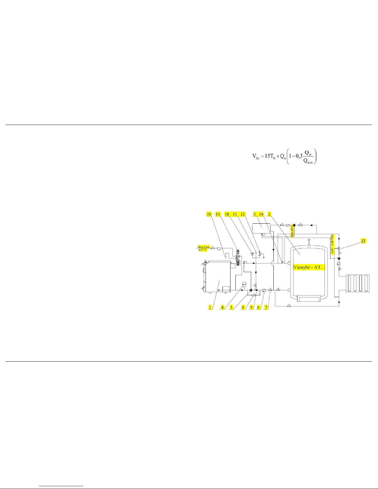
5.3. CONNECTION TO THE HEATING SYSTEM
Requirements for connection to the heating system:
- The boiler must be connected to the heating system according the project
developed by heat technology specialists, either, the works may be carried out independently by a
highly qualified, well-experienced plumber - welder, who has got well familiarized with the boiler
design and with this description.
- The boiler can be connected to the heating system (incl. an expansion tank),
with the operating pressure no higher than 1.5 bar.
- If the system pipes are equipped with valves that switch off the boiler from the
heating system, they should be fully opened. To avoid an accident due to negligence, after
opening the valves, please, remove their handles.
- The system must be equipped with a safety valve, which maintains the
maximum operating pressure of 1.5 bar in the heating system.
- To avoid condensation, which can shorten the life span of the boiler by several
times, the heating system must be installed in such a way so that the temperature of the return
heat carrier (water) is at least 60°C. Such a temperature of the heat carrier (water) is too high for
heating a living space, therefore, a minor heating circuit of heating system should be installed. For
the purpose, the system should be equipped with a three-way or four-way valve or a thermostat.
- The system must be equipped with a recycling pump, mounted in the return
water line to ensure a better circulation of the heat carrier and a more even distribution of
temperature in the boiler. If the circulation water pump is fitted in the water supply line, there is
generated a direct water flow in the boiler, whereby the water poorly distributed and mixed in the
boiler, especially in the upper front part of the boiler. There may emerge a significant temperature
difference between the water in the upper front part and at the outlet of the boiler. The
temperature controller and the thermometer are mounted on the top front of the boiler, thus, when
the recycling pump is in the wrong place, it can result in inaccurate adjustment of the air damper
position, while the boiler will not work in the optimal mode.
In order to fill the chamber1 with a fuel during combustion, open the chimney valve 3 and
close a secondary air supply valve 17. Hang off the chain 11 from the primary air suction valve 8;
the valve, as well as the bottom door 16 must be closed. Then, carefully semi-open the top door,
wait 2-3 seconds, and carefully open the top door. The smoke should not enter the room. If the
room gets smoked, it means that any of the valves may be still closed, or the primary air suction
valve is still opened. After loading a fuel to the chamber, hook the chain 11 to the primary air
suction valve 8 for the normal fuel burning monitoring process. Open the secondary air supply
valves 17.
When the burning is in progress, ashes cover the firegrating, therefore burning intensity
decreases, and boiler output capacity drops, as well. For this reason, the fuel must be shaken and
raked. You must rake through the slots in the inner door. Take the ashes away in time. Strewn
ash heap hinders primary air access to the combustion zone.
When in use, the boiler should operate within 100-80% limits of its rated output capacity.
To ensure such operating conditions, if there is a need, heat accumulators (accumulation tanks)
should be employed.
When firing the wood, you can load the chamber fully and set the fire. Mixed fuel
provides the longest duration of burning in the combustion chamber, for instance, wood, coal, and
sawdust. Good results can be obtained when burning a mixture of coal 60% and sawdust 40%
(according to weight).
NOTICE! When firing coal, only a half the chamber can be stocked, while firing
other kinds of fuel, you can load the chamber fully provided that the fuel does not fall off
over the top door.
NOTICE! Firing household waste in the boiler is strictly prohibited. In particular, all
types of plastics waste. The boiler is not intended for that. Firing this type of waste not only sots
the boiler and the chimney walls, but also discharges, along with the smoke, a lot of emissions to
the environment. Save the nature - and your health!
Try to use as a dry fuel as possible. This will improve the efficiency of the boiler,
increase its power output. Keep in mind that a part of the heat, generated during combustion, is
consumed for evaporation of the water contained in the fuel; so, the more water is in the fuel, the
more heat is consumed for it –and the less of it remains for space heating.
To extend the chamber burning process, use high-calorific fuel. Also, note that the
chamber burning duration depends on the loaded volume of firewood, as well as on its weight.
From time to time, if necessary, clean the boiler and the chimney. Be sure to clean
the boiler from soot and tar at the end of the heating season. Otherwise, water and various acids,
accumulated in the resin, can cause damage to the walls of the boiler.
At the end of the heating season, do not leave the system dewatered, since the boiler
will start to rust from the inside.
6.4. CLEANING
The ash accumulated under or over the firegrating, can hinder air access to the
combustion chamber. Therefore, before each heating, we recommend to clean the ash from the
ash box and the firegrating. Do not collect the ash to combustible vessels - plastic containers,
cardboard boxes, and so on. We recommend to use a metal container for the ash. Do not pour
out the ashes in recycle bins or other combustible places because of possible fire hazard. Wait for
it to cool down completely. You can use the ash as fertilizer as well.
To ensure the efficient operation of the boiler, clean the accumulated ashes and soot
from inner surfaces of the boiler. Cleaning frequency depends on the thickness of the
accumulated ashes and soot layer, which, in turn, is subject to the nature of the heating. A
regularly used boiler should be cleaned 2-3 times a month.
NOTICE! Do not clean the boiler during its heating.

Sirijus 20, 30 Sirijus 20, 30
Sirijus 20, 30 (13.05) V1 LT Sirijus 20, 30 (13.05) V1 LT
6. OPERATION OF THE BOILER
NOTICE! The boiler can be serviced only by adults who have read the boiler operation
manual.Before firing the boiler for the first time, please check the following:
- the heating system is filled in,
- the air is removed from the heating system,
- the cleaning openings of the chimney channels are closed.
The inner surfaces of the boiler can dew when you fire the boiler at low output capacity
- when the temperatures of heat carrier and burning products in the boiler are low (mostly it
happens in early autumn or spring when demand for heat is not strong). To avoid dewing, we
recommend you:
- as fast as possible reduce difference between temperatures of discharge and return
heat carrier.
- maintain the temperature of return heat carrier not lower than 60°C.
6.1. FIRING
Please fully open the chimney valve 3 (see Picture 1), and close secondary air supply
valve 17. After opening a bottom door 16 and an inner door 9, place the chopped dried
firewood or wood chips on the firegrating 6 and fire them.
NOTICE! When firing the boiler, the top door 15 must be closed.
6.2. ADJUSTMENT OF DRAFT CONTROL
Draft control "Honeywell" FR124 is included to the scope of supply of the boiler. Draft
control is established in accordance with his instructions.
The draft control should be screwed in when filling the heating system with the heat
carrier (water) so that water could almost run through the tube of the draft control. Then, using a
grind or a sealing tape, please seal the thread joint of the draft control; screw in the draft control
into the special slot. When screwing in the draft control during filling of the system, you can for
sure avoid an airlock in that place and improve the performance of the draft control.
When firing the boiler for the first time, you need to adjust the draft control.
The gap between divisions of the thermostat is 10°C. Heat the water in the boiler up to
70°C, hook a chain 11 (see Picture 1) from the temperature controller lever 12 to the primary air
suction valve 8, at the bottom door. Adjust the temperature controller lever so that the scale
reading could match the reading of the boiler thermometer, the length of chain 11 is selected so
that the primary air suction valve is closed. Keep in mind that the bolt, that fixes the temperature
controller lever to the plug, should be in front, while the lever should be positioned as shown on
Picture 1, that is, sloped forward up to the angle of ~ 30°. If all the doors are hermetically closed
and the boiler operates at power no less than 50%, the further combustion process is
automatically maintained by the temperature controller according to the preset temperature of
the heat carrier.
6.3. HEATING
When the fuel gets fired, please close the inner door 9 and the bottom door 16. Open the
top door 15 and add for fuel. After heating up the boiler, close the top door. Thus, smoke in the boiler
will form curves, and the heat carrier will take a maximum amount of heat. Open secondary air supply
valve 17. You can monitor boiler operation according to the colour of chimney discharge smoke. The
smoke must be thin and light. If the smoke is thick and dark, the secondary air supply does not
suffice.
Recommended scheme of boiler connection to the system is provided on Picture 2.
The boiler operates efficiently at rated power, therefore, it is recommended to install an
accumulation tank into the heating system. The minimal capacity of the accumulation tank is
calculated according to the formula:
Where:
VSp- capacity of the accumulation tank, l;
T B- burning time, hr,
Q n- rated power of the boiler, kW,
Q H- minimal heating power to heat premises, kW,
Q min - minimal heating power of the boiler, kW.
Capacity of the accumulation tank is approximately calculated with the assumption that a
minimal capacity of the accumulation tank of 50 litres comes up to every kilowatt of rated power of
the boiler.
Picture 2
Recommended scheme of boiler connection to the system with accumulation tank
1. Boiler. 2.Accumulation tank “Vienybe - AT...” 3.Water heater. 4. Expansion tank. 5.Recycling
pump. 6.Water strainer. 7.Shutter. 8.Reverse valve. 9.Thermostat. 10.Manometer 11.Bleed
valve. 12.Safety valve. 13.Three-way mixing valve. 14. Temperature controller of the recycling
pump. 15. Thermostatic cooling valve “Regulus” DBV-1. 16.Drainage.

Sirijus 20, 30 Sirijus 20, 30
Sirijus 20, 30 (13.05) V1 LT Sirijus 20, 30 (13.05) V1 LT
5.4. CONNECTION TO THE BOILER COOLING SYSTEM
For protection of the boiler against overheating, the system must be equipped with a
thermostatic cooling valve. We recommend to install the thermostatic cooling valve "Regulus"
DBV-1 (Czech Republic). The valve must be installed in accordance with the manufacturer's
description.
Technical data of the valve “Regulus” DBV-1:
Opening temperature: 100 °C (+0°C -5 °C)
Maximal temperature: 120 °C
Maximal pressure of the boiler 4bar
Maximal pressure of the cold water system 6bar
Nominal water discharge
at the pressure difference of 1 bar 1,8m3 /hr at 110°C
This valve should be installed as close to the boiler water conduit pos. 20 as possible
(see Picture 1). It can be mounted in a vertical or horizontal position. The valve must not be
mounted with a valve head downward (see Picture 3).
Forbidden Position
Picture 3
Mounting positions of the thermostatic cooling valve “Regulus” DBV-1
A valve tube “A” (see Picture 4) is connected to the cold water conduit; pressure in the
system should not exceed 6 bar, though, pressure in the cold water system should be
approximately 2 times greater than in the heating system, but at least 2 bar. A valve tube “B” must
be connected to the return water pipe of the boiler pos. 19 (see Picture 1). This way of the cold
water supply into the system will cool the boiler and avoid overheating of the boiler. Excessive
system pressure is removed through the valve tube “C”, so, that the tube must be connected to
the drainage. Minimal diameter of connecting valve pipes is DN16.
This manual suits for next models
1
Table of contents
Popular Boiler manuals by other brands

Tarm Biomass
Tarm Biomass SOLO INNOVA 30 Installation and operation manual

Fröling
Fröling PT4e 200 installation instructions

Rinnai
Rinnai QP85N User's information manual

Riello
Riello Condexa PRO Series Installation, Technical and Maintenance Manual

Curtis
Curtis WB5N user guide

Froling
Froling T4e 200 installation instructions

DOMUSA
DOMUSA Jaka HFD Installation and operating istructions

Immergas
Immergas ARES 440 TEC ERP manual

Fröling
Fröling PE1 Pellet 7 installation instructions

HydroTherm
HydroTherm HeatNet KN-20 Field assembly instructions

FULTON
FULTON Endura EDR-750 Nstallation, operation and maintenance manual

Atmos
Atmos InterCombi installation instructions