3
1. Information Disposal of packaging ............................................................................ 4
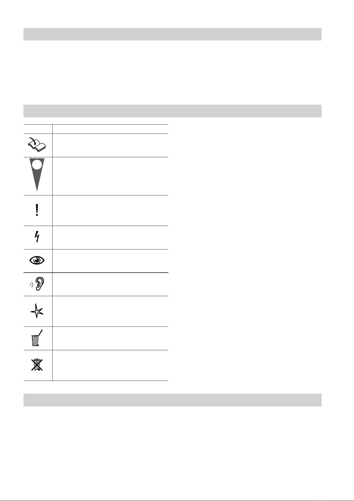
Symbols ................................................................................................. 4
Intended use .......................................................................................... 4
Product information ................................................................................ 5
System examples .................................................................................. 5
2. Preparing for installation Clearance dimensions ........................................................................... 6
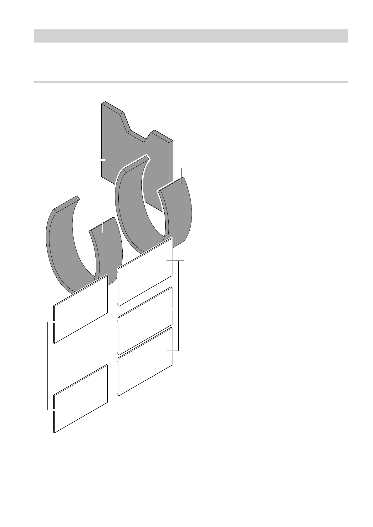
Thermal insulation components ............................................................. 7
■Thermal insulation pack 1 ................................................................... 7
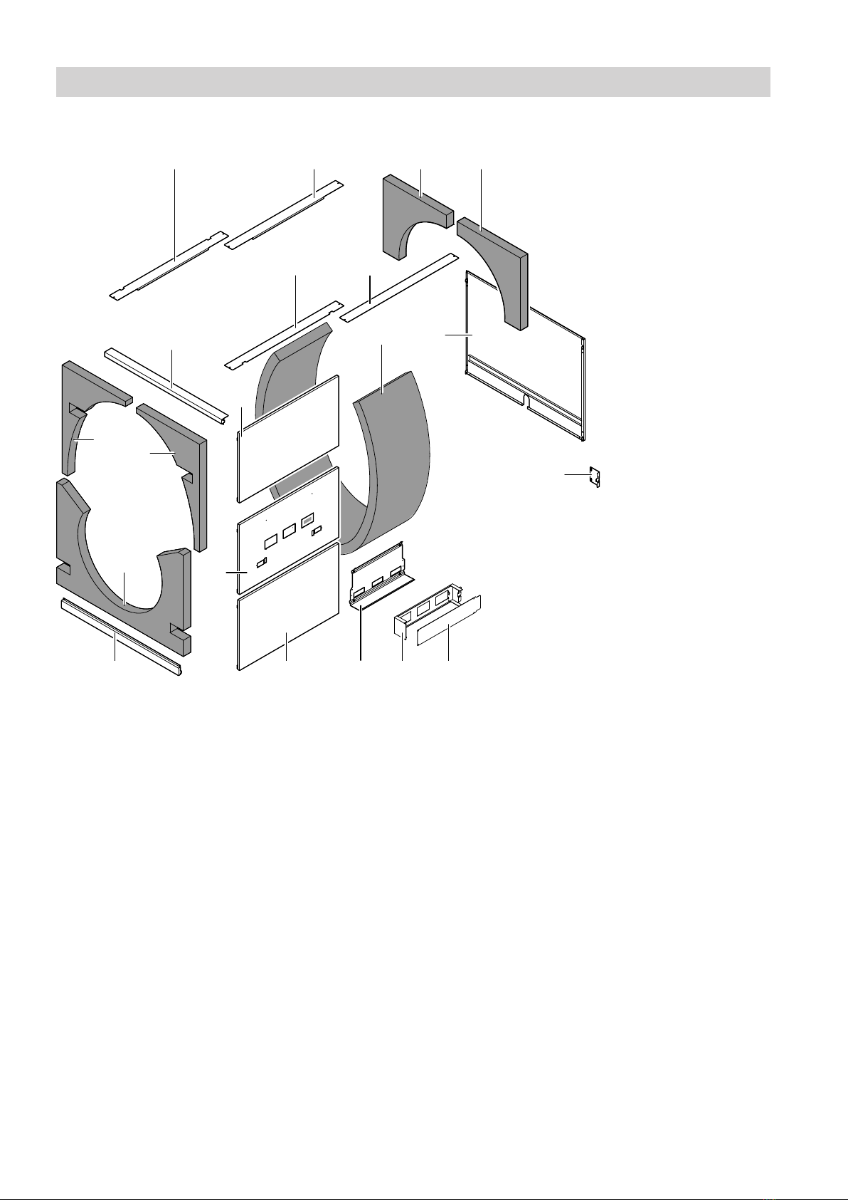
■Thermal insulation pack 2 ................................................................... 8
■Thermal insulation pack 3 ................................................................... 9
■Components in the combustion chamber ........................................... 10
3. Installation sequence Siting and levelling the boiler ................................................................. 11
Changing the boiler door opening ......................................................... 12
Combustion chamber sight glass ........................................................... 12
■Mounting the combustion chamber sight glass .................................. 12
■Closing off the sight glass aperture on burners without ventilation
connection .......................................................................................... 13
Connections on the heating water side .................................................. 14
Making the safety connection and testing for tightness ......................... 15
Fitting the thermal insulation .................................................................. 15
■Boiler body thermal insulation ............................................................ 16
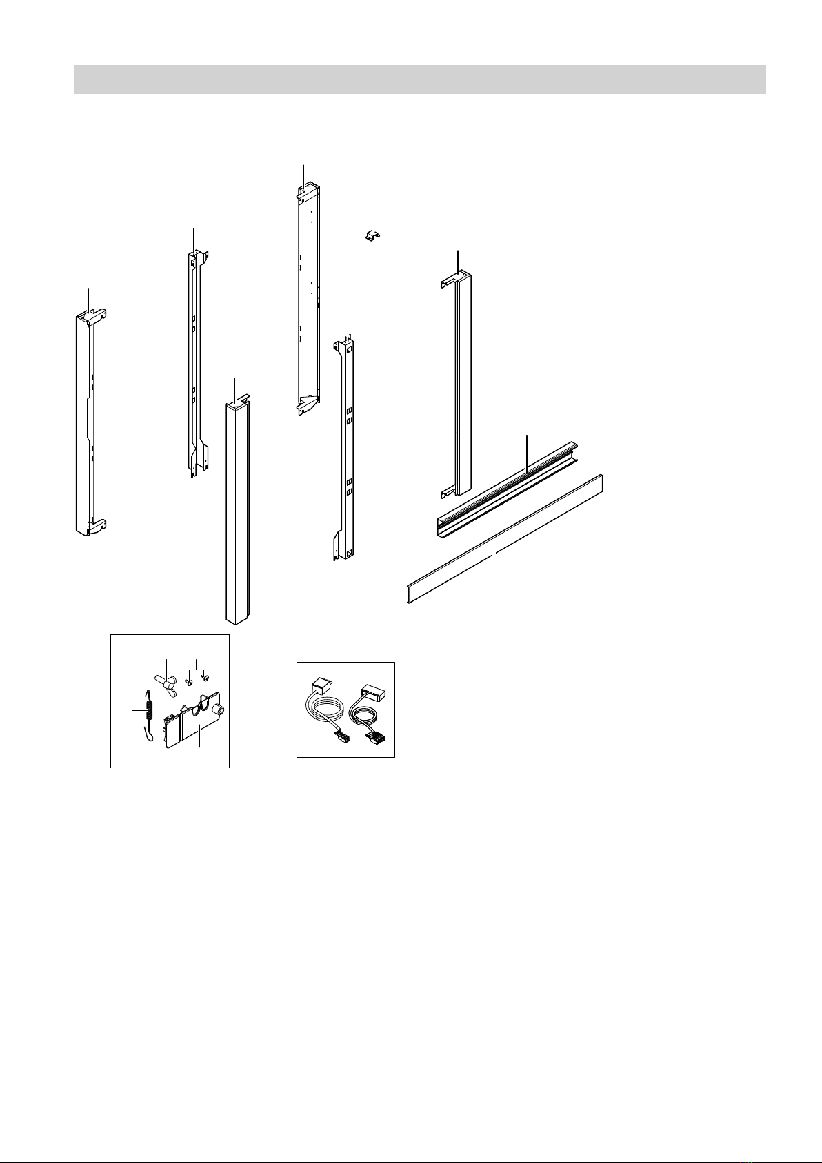
■Wing screws in the top and base rails ................................................ 17
■Front and back rails ............................................................................ 18
■Centre rail ........................................................................................... 19
■Aligning the rails ................................................................................. 20
Mounting the control unit ....................................................................... 21
■Control unit mounting bracket, control unit back section and burner
cables ................................................................................................. 21
■Remaining side panels ....................................................................... 25
■Cable trunking .................................................................................... 25
Fitting additional thermal insulation ....................................................... 26
■Front thermal insulation and front panels ........................................... 26
■Thermal insulation (back) and back panels ........................................ 27
■Covers ................................................................................................ 28
■Type plate ........................................................................................... 29
Connections on the flue gas side ........................................................... 30
Mounting the burner ............................................................................... 30
Pressure switch ..................................................................................... 31
■Pressure switch .................................................................................. 31
Commissioning information ................................................................... 32
Index
5457380