manuals.online logo
Brands
  1. Home
  2. •
  3. Brands
  4. •
  5. Viessmann
  6. •
  7. Boiler
  8. •
  9. Viessmann VITOROND 200 Instruction manual

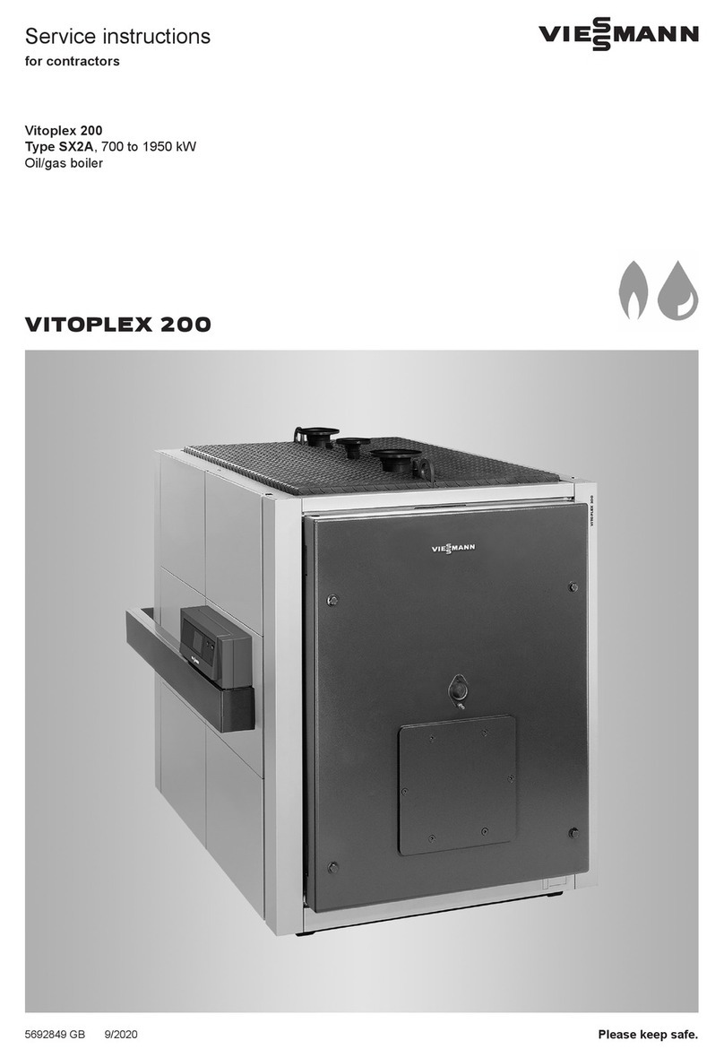
Viessmann VITOROND 200 Instruction manual

Other manuals for VITOROND 200

10

This manual suits for next models

5

Other Viessmann Boiler manuals

Viessmann VITODENS 300-W User manual

Viessmann

Viessmann VITODENS 300-W User manual

Viessmann VITOLIGNO 300-P Operating instructions

Viessmann

Viessmann VITOLIGNO 300-P Operating instructions

Viessmann VITORADIAL 300-T Type VR3 Operating instructions

Viessmann

Viessmann VITORADIAL 300-T Type VR3 Operating instructions

Viessmann VITOROND 200 VD2A-125 User manual

Viessmann

Viessmann VITOROND 200 VD2A-125 User manual

Viessmann VITOPLEX 100 User manual

Viessmann

Viessmann VITOPLEX 100 User manual

Viessmann VITROND 200 User manual

Viessmann

Viessmann VITROND 200 User manual

Viessmann Vitocell 050-E Quick guide

Viessmann

Viessmann Vitocell 050-E Quick guide

Viessmann Vitodens 100-W Quick guide

Viessmann

Viessmann Vitodens 100-W Quick guide

Viessmann VITOLIGNO 300-P User manual

Viessmann

Viessmann VITOLIGNO 300-P User manual

Viessmann VITOCROSSAL Series User manual

Viessmann

Viessmann VITOCROSSAL Series User manual

Viessmann Vitodens 222-F Operating instructions

Viessmann

Viessmann Vitodens 222-F Operating instructions

Viessmann VITOCROSSAL 300 Operating instructions

Viessmann

Viessmann VITOCROSSAL 300 Operating instructions

Viessmann VITODENS 300-W Quick start guide

Viessmann

Viessmann VITODENS 300-W Quick start guide

Viessmann VITOFLEX 300-UF User manual

Viessmann

Viessmann VITOFLEX 300-UF User manual

Viessmann Vitodens 200 WB2 11-44 User manual

Viessmann

Viessmann Vitodens 200 WB2 11-44 User manual

Viessmann Vitodens 111-W Quick guide

Viessmann

Viessmann Vitodens 111-W Quick guide

Viessmann VITOPLEX 100 Operating instructions

Viessmann

Viessmann VITOPLEX 100 Operating instructions

Viessmann Vitodens 200-W System Quick start guide

Viessmann

Viessmann Vitodens 200-W System Quick start guide

Viessmann VITOMAX 200-HW Training manual

Viessmann

Viessmann VITOMAX 200-HW Training manual

Viessmann VITORADIAL 300-T Operating instructions

Viessmann

Viessmann VITORADIAL 300-T Operating instructions

Viessmann Vitodens 222-F B2TB User guide

Viessmann

Viessmann Vitodens 222-F B2TB User guide

Viessmann Vitomax LW Training manual

Viessmann

Viessmann Vitomax LW Training manual

Viessmann Vitodens 200-W System Quick guide

Viessmann

Viessmann Vitodens 200-W System Quick guide

Viessmann VITODENS 050-W Quick guide

Viessmann

Viessmann VITODENS 050-W Quick guide

Popular Boiler manuals by other brands

IDEAL IMAX XTRA EL 320 user guide

IDEAL

IDEAL IMAX XTRA EL 320 user guide

UTICA BOILERS BC3D Installation, operation & maintenance manual

UTICA BOILERS

UTICA BOILERS BC3D Installation, operation & maintenance manual

Lochinvar SOLUTION 260000 Installation & service manual

Lochinvar

Lochinvar SOLUTION 260000 Installation & service manual

Weil-McLain EG 6 Series manual

Weil-McLain

Weil-McLain EG 6 Series manual

RBI LCD Series Installation & operation manual

RBI

RBI LCD Series Installation & operation manual

Baxi MainEco Combi 28 Installation and service manual

Baxi

Baxi MainEco Combi 28 Installation and service manual

Unical ALKON R 24 Installation and Servicing Manual

Unical

Unical ALKON R 24 Installation and Servicing Manual

Automatic Heating Gasogen Installation and Servicing Manual

Automatic Heating

Automatic Heating Gasogen Installation and Servicing Manual

Alpha GasSaver GS-1 Installation and servicing instructions

Alpha

Alpha GasSaver GS-1 Installation and servicing instructions

Baxi ROCA LAURA PLUS 28/28 Operating, cleaning and maintenance instructions for the user

Baxi

Baxi ROCA LAURA PLUS 28/28 Operating, cleaning and maintenance instructions for the user

Vaillant uniSTOR VIH SW GB 500 BES operating instructions

Vaillant

Vaillant uniSTOR VIH SW GB 500 BES operating instructions

Kärcher HWE 4000 Gas manual

Kärcher

Kärcher HWE 4000 Gas manual

Radijator BIO max 23.1 instruction manual

Radijator

Radijator BIO max 23.1 instruction manual

Granby BKC Installation, operation and maintenance manual

Granby

Granby BKC Installation, operation and maintenance manual

Brunner BSV 20 Instructions for use

Brunner

Brunner BSV 20 Instructions for use

Potterton 50e Installation and Servicing Manual

Potterton

Potterton 50e Installation and Servicing Manual

UTICA BOILERS TriFire Assembly instructions

UTICA BOILERS

UTICA BOILERS TriFire Assembly instructions

ECR International UB90-125 Installation, operation & maintenance manual

ECR International

ECR International UB90-125 Installation, operation & maintenance manual

manuals.online logo
manuals.online logoBrands
  • About & Mission
  • Contact us
  • Privacy Policy
  • Terms and Conditions

Copyright 2025 Manuals.Online. All Rights Reserved.

Product may not be exactly as illustrated.
Viessmann North America offers the side-mounted control option only.
This trademark is registered with the U.S. Patent and Trademark Office.
Technical Data Manual
Model Nos. and pricing: see Price List
V
VV
VI
II
IT
TT
TO
OO
OR
RR
RO
OO
ON
NN
ND
DD
D 2
22
20
00
00
00
0
Triple-pass hot water heating boiler
49 to 1 96 MBH / 144 to 321 kW
Vitorond 200
VD2A Series
Oil-/Gas-fired boiler
triple-pass sectional cast iron design
with Eutectoplex heat transfer surface and Therm-Control integrated
low temperature protection logic
for operation with modulating water temperatures
Heating input: 49 to 1 96 MBH
144 to 321 kW
5
3
5
4
7
8
7
v
1
.
2
7
/
2
1
Product Information
2VITOROND 200, VD2A
VITOROND 200
The Vitorond 2 is a triple-pass sectional
cast iron oil-/gas-fired boiler for commercial
heating applications.
Its Eutectoplex heat exchanger provides high
operational reliability and a long service life,
while the triple-pass design ensures
efficient, low-emission combustion.
The VD2A Series features Therm-Control
integrated low-temperature protection logic
and a redesigned return water distribution
system for a simplified design and system
integration.
he benefits at a glance:
HEfficient and reliable operation. Modulated
boiler water temperatures help conserve
energy by closely matching system output
to actual demand. Viessmann system
controls ensure consistent, maximum
system efficiency.
Combustion efficiency up to:
- oil 87.7%.
....................................................
- gas 84.8%...................................................
Thermal efficiency up to:
- oil 87.9%.....................................................
- gas 85.2%...................................................
HSimplified design and system integration
with Therm-Control integrated
low-temperature protection logic,
eliminating the need for a low-temperature
protection package or shunt pump.
No minimum boiler return water
temperature when used with Viessmann
Vitotronic controls.
HSimplified water connection. Wide water
galleries and a large water content provide
excellent natural circulation and a reliable
heat transfer. No minimum heating water
flow rate required.
HHigh operational reliability and a long service
life are achieved by the special Eutectoplex
gray cast iron heat exchanger. A uniform
heat transfer and controlled water flow,
together with inherent characteristics of the
cast iron sections, eliminate stress fractures,
counteract the formation of condensate and
extend the lifecycle of the boiler.
HLow environmental impact thanks to
low-emission combustion achieved by the
boiler’s triple-pass design.
HProblem-free transport into
difficult-to-access boiler rooms thanks to
sectional construction and low weight of
individual sections. The Fastfix system
facilitates a quick and easy installation.
HSimple, quick assembly of the individual
cast iron sections with new
tongue-and-groove system with silicone
sealant. The gasket seal is secured in
place by the double groove, and therefore
not subject to mechanical stresses.
HEasy cleaning access facilitated by a
hinged left- or right-swing combustion
chamber door providing easy access to all
three flue gas passageways from the front
of the boiler, reducing side clearance.
HEfficient and safe operation of the heating
system with Vitotronic digital boiler and
heating system controls. Tailored to suit
every requirement, these controls cover all
known control strategies and applications.
Standardized LON BUS enables complete
integration into building management
systems. Optional integration into the
Vitocontrol control panel.
HConsistent and reliable DHW production
with indirect-fired Vitocell 1 steel or
Vitocell 3 stainless steel tanks.
Tanks may be combined into multiple-tank
batteries for applications requiring larger
quantities of hot water.
HComprehensive standard equipment saves
valuable time in installation and sourcing
of product. The supply and return header
system is pre-built for left or right
connections and positions components
properly.
HBoilers, controls, domestic hot water
tanks, and heating system components
are design-matched to work together. All
components are compatible and are
therefore quickly and easily installed.
5
3
5
4
7
8
7
v
1
.
2
Product Information
Cross-Section
VITOROND 200, VD2A 3
Viessmann North America offers the side-mounted control option only.
AExtremely effective 4” / 1 mm
thick insulation
BThird pass
CVitotronic control - intelligent and
easy to install, operate and service
DBurner door insulation
ELow-emission burner (Weishaupt or
Riello)
FSecond pass
GEutectoplex heat exchanger surface
constructed from homogeneous
special gray cast iron
HCombustion chamber
5
3
5
4
7
8
7
v
1
.
2
Technical Data
4VITOROND 200, VD2A
echnical Data
Boiler model VD2A- 125 160 195 230 270
Input (oil)*1MBH 49 628 765 9 2 1 59
kW 144 184 224 264 31
Input (gas)*1MBH 5 8 65 792 934 1 96
kW 149 19 232 274 321
Output (oil/gas)*2MBH 433 553 672 794 932
kW 127 162 197 232 272
Combustion efficiency (oil) % 87.7 87.3 87.3 87.3 87.3
Combustion efficiency (gas) % 84.7 84.8 84.8 84.8 84.8
hermal efficiency (oil) % 87.9 87.6 87.4 87.3 87.2
hermal efficiency (gas) % 85.2 85.1 84.8 84.8 84.7
Number of cast iron sections 4 5 6 7 8
Cast iron block dimensions*3
Length (dimension f)
Width (dimension c)
Height (dimension b)
in
mm
in
mm
in
mm
26½
67
31
79
35
884
33
84
31
79
35
884
39¾
1 1
31
79
35
884
46½
118
31
79
35
884
53¼
135
31
79
35
884
Cast iron section dimensions*3
Front section (with combustion
chamber door)(dimension j)
Intermediate section
(dimension i)
Rear section (with flue gas
collar)
in
mm
in
mm
in
mm
35 x 31 x 11½
885 x 79 x 29
34 x 26¾ x 6¾
86 x 68 x 17
35 x 34 x 1 ½
885 x 86 x 27
Dimensions (with insul.
jacket)*3
Total length (dimension g)
Total width with side-
mounted Vitotronic NR2
control (dimension e)
Total width (dimension d)
Total height with boiler base
(dimension h)
Total height with supply
header (dimension a)
in
mm
in
mm
in
mm
in
mm
in
mm
35¾
9 5
4 ½
1 3
34
86
39½
1 7
58½
1485
42¼
1 75
4 ½
1 3
34
86
39½
1 7
58½
1485
49
124
4 ½
1 3
34
86
39½
1 7
58½
1485
55½
141
4 ½
1 3
34
86
39½
1 7
58½
1485
62¼
158
4 ½
1 3
34
86
39½
1 7
58½
1485
Weight
Front section (with combustion
chamber door)
Intermediate section
Rear section (with flue gas
collar)
Cast iron heat exchanger block
Overall weight
(complete with jacket,
without burner)
lbs
kg
lbs
kg
lbs
kg
lbs
kg
lbs
kg
352
16
22
1
242
11
1122
51
12 1
545
352
16
22
1
242
11
1353
615
1441
655
352
16
22
1
242
11
1584
72
1675
76
352
16
22
1
242
11
176
8
1874
85
352
16
22
1
242
11
1991
9 5
2127
965
*1 Input ratings are based on AN I Z21.13a*C A 4.9a-2007 - Gas Fired team and Hot Water Boilers;
C A B140.7-05 - Oil Burning Equipment - team and Hot Water Boilers;
C A B140.0-03 - Oil Burning Equipment - General Requirements;
UL 726 - 7th ed. - Oil-Fired Boiler Assemblies;
and UL 795 - Commercial Industrial Gas Heating Equipment.
*2Output ratings are based on the IBR BT -2000 “method to determine efficiency of commercial space heating boilers”.
*3 Inch dimensions are rounded to the nearest ¼”.
5
3
5
4
7
8
7
v
1
.
2
Technical Data
VITOROND 200, VD2A 5
echnical Data
Boiler model VD2A- 125 160 195 230 270
Boiler water content USG
ltr
32
122
41
154
49
186
57
217
66
249
Max. boiler temperature*4
(= fixed high limit)
°F
°C
25
121
25
121
25
121
25
121
25
121
Max. allow. operating
pressure*5 psig 85 85 85 85 85
Boiler connections*6
Boiler supply and return
Drain valve - sediment faucet
in
in 2½
¾
2½
¾
2½
¾
2½
¾
2½
¾
Heating surface area
Flue gas side ft.2
m253
4.9
7
6.5
85
7.9
1 2
9.5
117
1 .9
Water side ft.2
m243
4.
57
5.3
71
6.6
85
7.9
99
9.2
Flue gas
– Temperature (gross)*7
– Flue gas mass flow rate
With minimum heating input
and a 2-stage burner
(operation of stage 1)
– Temperature
– Flue gas mass flow rate at
minimum input rate
°F
°C
lbs/h
kg/h
°F
°C
lbs/h
kg/h
365
185
47
213
257
125
282
128
365
185
6 2
273
257
125
362
164
365
185
732
332
257
125
439
199
365
185
864
39
257
125
516
234
365
185
1 14
457
257
125
6 4
274
Standby loss
based on max. heating input
and hot water supply and
return temperatures of
167 / 14 °F
75 / 6 °C
% .4 .38 .28 .25 .25
Vent pipe collar outer ∅*8 in
mm
8
2
8
2
8
2
8
2
8
2
Flue gas resistance “w.c. .26 .38 .4 .48 .64
Flue gas volume
of combustion chamber and
flue gas passageways
ft.3
m34.9 9
.139
6. 39
.171
7.169
.2 3
8.299
.235
9.429
.267
Required flue draft
Category I
Pa
“w.c.
Positive pressure
Category III
Pa
“w.c.
2
. 8
2
. 8
2
. 8
2
. 8
2
. 8
*4 The maximum supply operating temperature (= max. adjustable high limit) lies approx. 27°F / 15°C below the fixed high limit setting.
*5 May be less in some Canadian provinces.
*6 Connections for boiler connection kit (standard equipment).
*7 Combustion results are based on 13.0% CO2with fuel oil #2 and 10% CO2with natural gas, as well as
a system supply temperature of 167°F / 75°C, and a system return temperature of 140°F / 60°C.
Measured flue gas temperature with a combustion air temperature of 68°F / 20°C and a boiler water temperature of 176°F / 80°C.
*8 Vent pipe collar diameter does not automatically indicate vent/chimney size. See page 20 for different venting options (categories).
"The combustion burner head material must be suitable for temperatures of at least 932°F / 500°C.
"For information regarding other Viessmann ystem Technology componentry, please reference documentation of respective product.
5354 787 v1.2
Technical Data
6VITOROND 200, VD2A
Legend
BD Boiler drain, ¾”
BWR Boiler water return
BWS Boiler water supply
CO Clean-out opening
FGC Flue gas collar
SG Sight glass
LWCO Low water cut-off
Burner Installation
The burner must be fitted to the
burner plate; installations direct to
the boiler door are not feasible.
Viessmann supplies a pre-drilled end
burner plate in accordance with the
supplied burner dimensions.
Note
For mounting burners with blast
tube diameters over 6” / 15 mm,
the door insulation (refractory
material) can be cut to the required
size.
The blast tube must protrude from
the thermal insulation on the boiler
door.
5
3
5
4
7
8
7
v
1
.
2
a
b
c
d
eg
BWS
BWR
FGC
LWCO
f
h
64” / 1623 mm*1
18¼” / 465 mm
18¼” / 465 mm
31¼” / 795 mm
38” / 97 mm
6¾” /
17 mm
*1 Dimension includes sub-base.
Please note: Inch dimensions are rounded to the nearest ¼”.
Fig. 1
i
j
Viessmann North America offers the
side-mounted control option only. Refer to
the side-mounted control dimension on
page 4.
Attention
25¼” / 64 mm
18¼” / 465 mm
∅6” / 15 mm
275 mm
1 7/8” /
Please note: Inch dimensions are rounded to the nearest ¼”.
5” / 125 mm
Fig. 2
Technical Data
Legend
SS Safety supply - connection to pressure relief valve
LWCO Low water cut-off
TG Temperature gauge
BWS Boiler water supply
LWCO
BWS
SS
TG
*1Single
Aquastat
(optional)
*1Dual
Aquastat
(optional)
95/8” / 245 mm
95/8” / 245 mm
57/8” / 148 mm 7¾” / 195 mm
193/8” / 49 mm
Please note: Inch dimensions are rounded to the nearest 1/4”.
Fig. 3
VITOROND 200, VD2A 7
Boiler Connection Kit (Standard Equipment)
*1
Boiler must be controlled via Viessmann
Vitotronic herm-Control logic in order to
prevent the formation of flue gas
condensation at all local site return water
temperatures. Consult your local Viessmann
echnical Representative for other possible
control options.
5354 787 v1.2
IMPOR AN
Technical Data
8VITOROND 200, VD2A
Clearances to Combustibles
Boiler model VD2A- 125 160 195 230 270
Top 6” / 15 mm
Sides 6” / 15 mm
Flue (oil) 9” / 229 mm
Flue (gas) 6” / 15 mm
Front 6” / 15 mm
Floor non-combustible
HAvoid air contamination by halogenated
hydrocarbons (e.g. as in sprays, paints,
solvents and cleaning agents)
HAvoid very dusty conditions
HAvoid high levels of humidity
HProtect against frost and ensure good
ventilation
Otherwise, the system may suffer faults and
damage. In rooms where air contamination
through halogenated hydrocarbons may
occur, install the boiler only if adequate
measures can be taken to provide a supply
Maintain 1” air clearance from uninsulated
hot water pipes to combustible material.
Boiler must not be installed on combustible
floor material.
Recommended Minimum Service Clearances
The combustion chamber door is factory
assembled to hinge on the left-hand side.
A right-hand hinge is feasible by rebuilding
the door hinge hardware.
Boiler
model
VD2A-
125 160 195 230 270
a1in
mm
47¼
12
55
14
63
16
71
18
79
2
b2Dependent on burner model
Inch dimensions are rounded to the nearest
¼”.
1Minimum clearance in front of boiler
2Burner height [plus 8” (2 mm) for door
clearance to wall].
Front clearances (dimension “a”) will allow
for easy removal of flue gas turbulator
inserts, as well as for full insertion of bristle
brush for heat exchanger cleaning.
Minimum side clearance of 20” / 500 mm
must be maintained for side-mounted
Vitotronic control.
5354 787 v1.2
IMPOR AN
IMPOR AN
2 ” /
5 mm
2 ” / 5 mm
24” /
6 mm
17 mm
17” /
43 mm
8” / 2 mm
Fig. 4
6¾” /
Top View
IMPOR AN
Technical Data
VITOROND 200, VD2A 9
Waterside Flow
The Vitorond 2 boiler is designed for closed loop, forced
circulation, hot water heating systems only.
The recommended water flow rate through the Vitorond 2
is based on a temperature difference of between 2 °F and
4 °F / 11°C and 22°C (see table below). When a balancing
valve is used for proper balancing and water flow through the
boiler, the valve should be installed 5 pipe diameters from any
fittings and 1 pipe diameters from circulation pumps to allow
for laminar flow.
The consulting engineer or contractor should review the
system design if more balancing valves are required to
properly balance the system.
Viessmann can supply TA (Victaulic) balancing valves upon
request. The balancing should be carried out by a certified
balancing firm prior to boiler start-up. Please contact
Viessmann for your closest certified balancing firm.
VD2A-125 and VD2A-16
VD2A-195
VD2A-23 and VD2A-27
Recommended Flow Rates
Boiler model VD2A- 125 160 195 230 270
2 °F ∆t*1
4 °F ∆t
11°C ∆t
22°C ∆t
GPM
GPM
ltrs/s
ltrs/s
43
21
2.7
1.3
55
27
3.4
1.7
67
33
4.2
2.1
79
39
5.
2.5
92
46
5.8
2.9
*1 ∆t= temperature difference
5
3
5
4
7
8
7
v
1
.
2
34 5 8 1 15 2 25 3
35
18 22
13 118866
44 132
5
8
1
15
2
25
3
35
5
4
8
1
4
6
2
3.2
32
4
2
16
14
12
1
8
624
7
28
mbar
”W.C.
m3/h
USG/min
Flow rate
Pressure drop
A B C
Fig. 5
Technical Data
1 VITOROND 200, VD2A
Burner Calibration
Weishaupt burners / Riello burners
A Vitorond 2 , VD2A boiler with a high-performance gas burner installed can achieve a
thermal efficiency of up to 85.2%, and up to 87.9% if equipped with a #2 oil burner as
follows:
Gas-fired
1 % volume CO2, 28 °F / 138°C net stack temperature, CO in ppm < 5
Oil-fired
13% volume CO2, 3 °F / 149°C net stack temperature, smoke spot - 1
(on the Bacharach Scale)
ee separate instructions supplied with the burner.
The maximum input published for each boiler size must not be exceeded.
Model Flue gas
resistance
mbar “w.c.
VD2A-125
VD2A-16
VD2A-195
VD2A-23
VD2A-27
.65
.95
1.
1.2
1.6
.26
.38
.4
.48
.64
Burner manufacturer
Weishaupt or Riello
Burner/Gas train approval
Standard approvals are CSA (for Canada) and UL (for U.S.). IRI and FM approved equipment
is also available - please inquire.
Electrical requirements
Weishaupt W Series and Riello burners are available in 12 VAC, single-phase, in a 6 Hz
configuration. It is generally acceptable to use voltages within ten percent of the supply
voltage. Available voltage inside boiler room must be provided at time of order. Ensure
appropriate disconnect means and overcurrent protection.
Natural gas pressure
Natural gas pressures and heating values as provided by the gas utilities vary greatly across
North America. Select the appropriate gas train accordingly. Low pressure gas trains have a
maximum input of 14 ”w.c.; high pressure gas trains have a maximum pressure of 5 psig.
Minimum gas pressures apply - please inquire. Gas pressures and heating values at site
must be provided at time of order.
5354 787 v1.2