Burner - Beckett
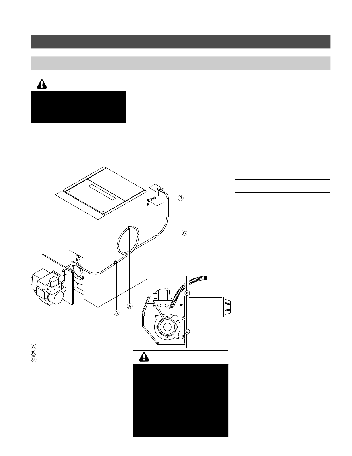
Fig. 2
3
Burner Set-up (Beckett)
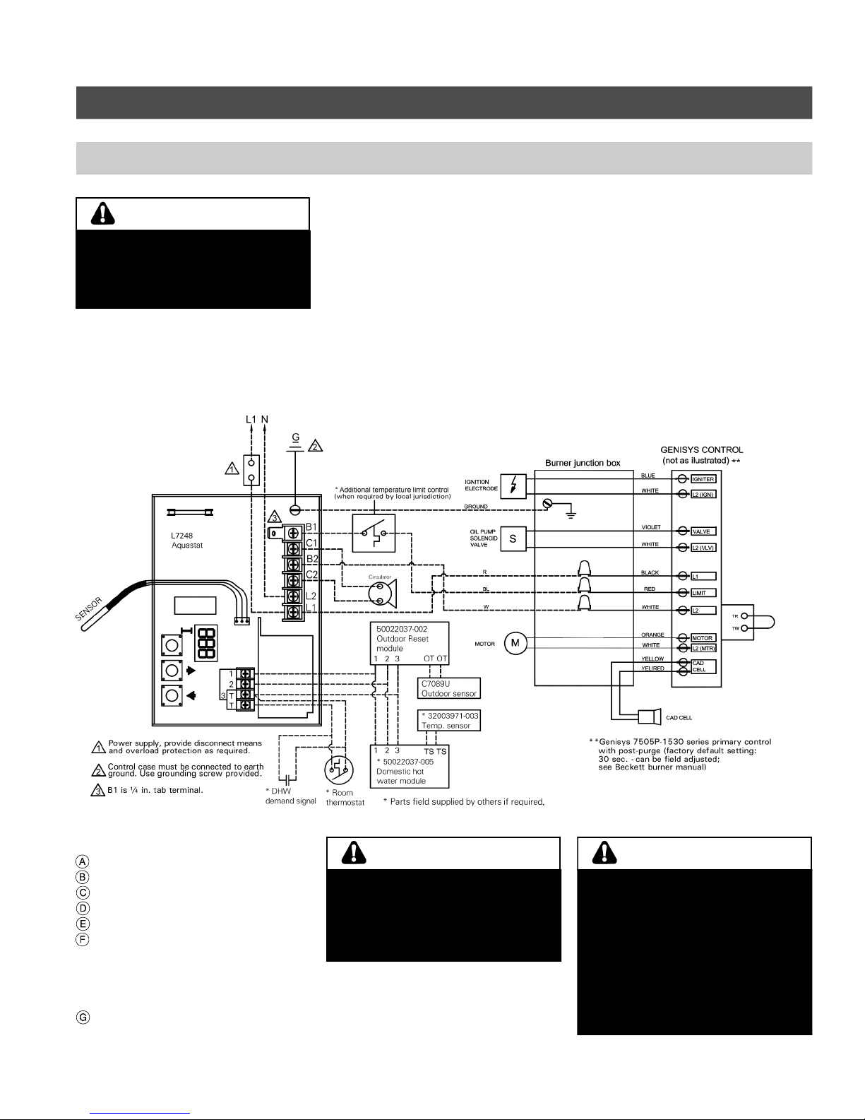
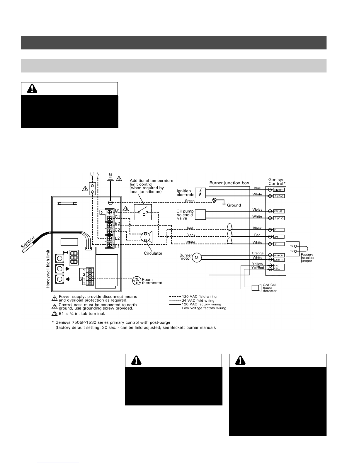
Electrical connections (with Aquastat control)
Installations must follow these codes
and requirements:
- National Electrical Code, ANSI/NFPA
70, latest edition and any addtional
national, state or local codes.
- In Canada, CSA C22.1 Canadian
Electrical Code Part 1 and any local
codes.
- Wirin must be N.E.C. Class 1. If
ori inal wire as supplied with boiler
must be replaced, type 105°C wire
or equivalent must be used. Supply
wirin to boiler and additional control
wirin must be 14 a. or heavier.
- Provide electrical round at boiler as
required by codes.
"
All field supplied nominal 120 VAC voltage wiring must be sheathed in a flexible metal conduit.
"
Disconnect means, overload protection and low water cut-off must be provided as required by local codes.
"
Connect incoming line voltage HOT (L1) wire to terminal L1, and N to terminal L2 of the Honeywell high limit control (see
wiring diagram on page 5.
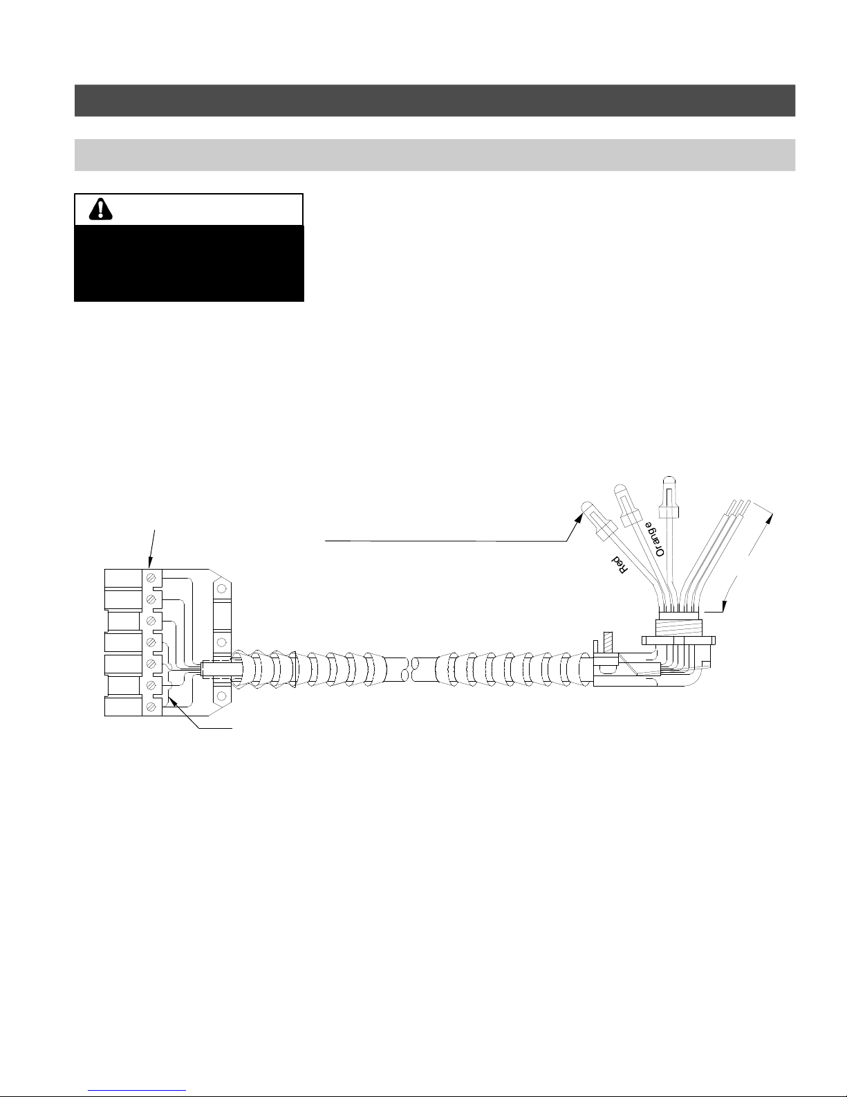
Legend
Cable strap (supplied)
Honeywell hi h limit control
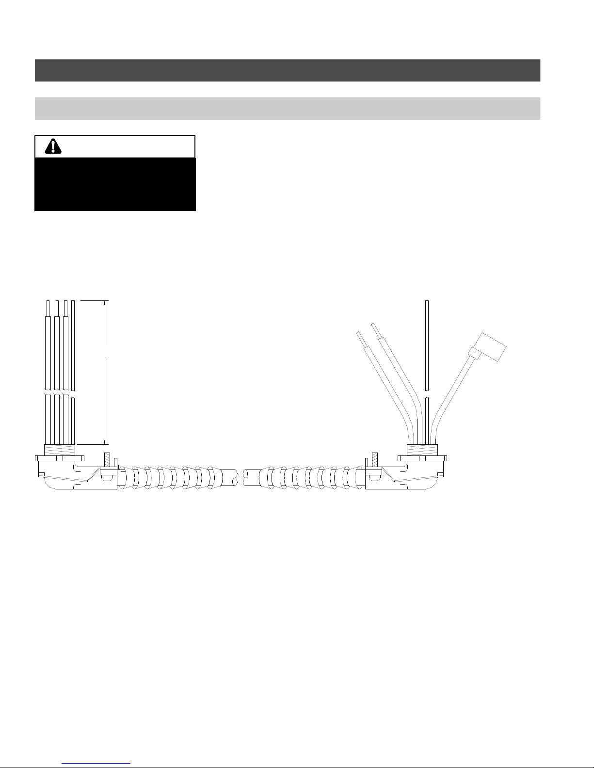
Burner wirin harness (supplied)
Burner wiring
The R7184 or GeniSys 7505P primary
control with valve-on delay (pre-purge)
and burner motor-off delay (post-purge
- factory default settings can be field
adjusted), requires a constant 120
VAC power source supplied to the
BLACK wire on the control (see wiring
diagram on following page).
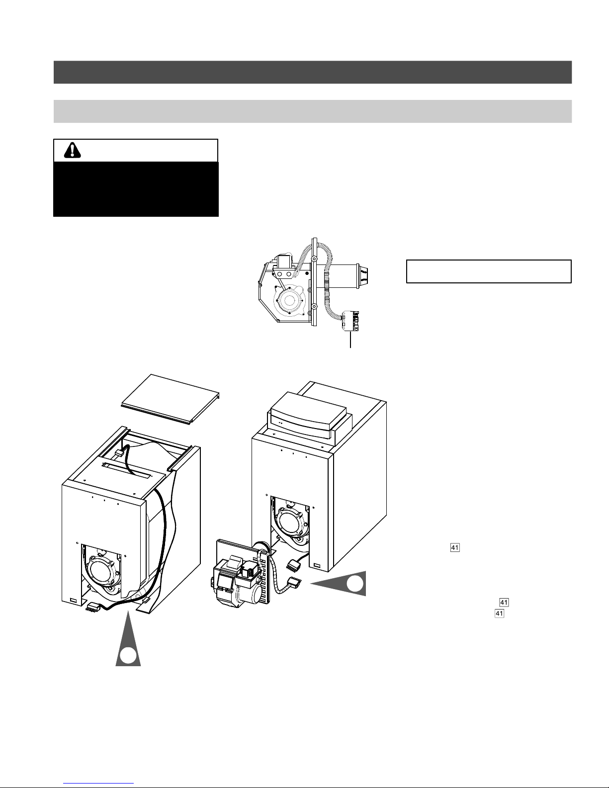
1. The cover mountin plate is not a
conduit connection point. Pass
conduit and attached connector
throu h the front openin in the
mountin plate or throu h one of the
knockouts on either side of the cover
and attach it directly to the
burner-mounted 4x4 electrical
junction box.
Room thermostat wiring
1. Install thermostat on inside wall
away from influences of drafts, hot
or cold water pipes, li htin fixtures,
television, sun rays or fireplaces.
2. Follow instructions supplied with
room thermostat. If it has a heat
anticipator, set heat anticipator in
thermostat to match power
requirements of equipment
connected to it. Boiler wirin
dia rams ive settin for standard
equipment.
5351 050 v2.5
Electric shock hazard. Can cause
severe personal injury or loss of life if
power source, including service
switch on boiler, is not disconnected
before installing or servicing.
WARN NG
Ensure that burner wiring harness is
properly attached and secured to the
boiler side panel using the supplied
cable straps as depicted above. The
cable strap must be coiled on the
boiler side panel so that no slack is
left, allowing the burner/boiler door
to be swung open without
disconnecting the burner wiring
harness from the burner. Failure to
heed this warning may result in
personal injury.
WARN NG
MPORTANT