View Sky Sensor User manual

1Rev 07 | Oct 2020 © 2020 View, Inc. All rights reserved.
Sky Sensor Body
Sky Sensor Base
Installation Guide
QDM-05-000045
Sky Sensor Installation Guide
The roof-mounted Sky Sensor provides
external light level data and infrared
temperature data to the View system
to allow optimization of tint levels for
each zone. The assembly includes the
Sky Sensor with a 50 ft length of CAT5
Ethernet cable attached.
Package Includes
1. Sky Sensor Body
2. Sky Sensor Base
3. 50 ft. length of CAT5 plenum rated Ethernet cable with an RJ45 pre-terminated
4. PN: 015-102018 L-com Wireless Indoor Shielded CAT6 Surge Protector (POE Coupler) Model: HGLN-CAT6J (Ships in
separate box)
Tools and Materials Required
1. Conduit (RMT or IMT) for roof mast
2. #2 Phillips screwdriver
3. NEMA 3S rated pull box (10 x 10 x 6”) or 4-Square Bell box
PoE Injector Requirements
1. For systems with Control Panel 2.0, use PoE injector with P/N: 015-101821-01
2. For systems with older Control Panel, use PoE injector with P/N: 330-101504
3. For CP 3.0, POE cable can be connected to Advantech POE switch (see CP 3.0 Data sheet for port options)
Additional Supporting Documentation
1. Sky Sensor Data Sheet - QDM-02-000062
2. Click here for CAT5 Termination Procedure.
3. For CP 3.0, POE cable can be connected to Advantech POE switch (see CP 3.0 Data sheet for port options).
4. Click here for Data Sheet for L-Com POE Coupler.

2Rev 07 | Oct 2020 © 2020 View, Inc. All rights reserved.
System Requirements
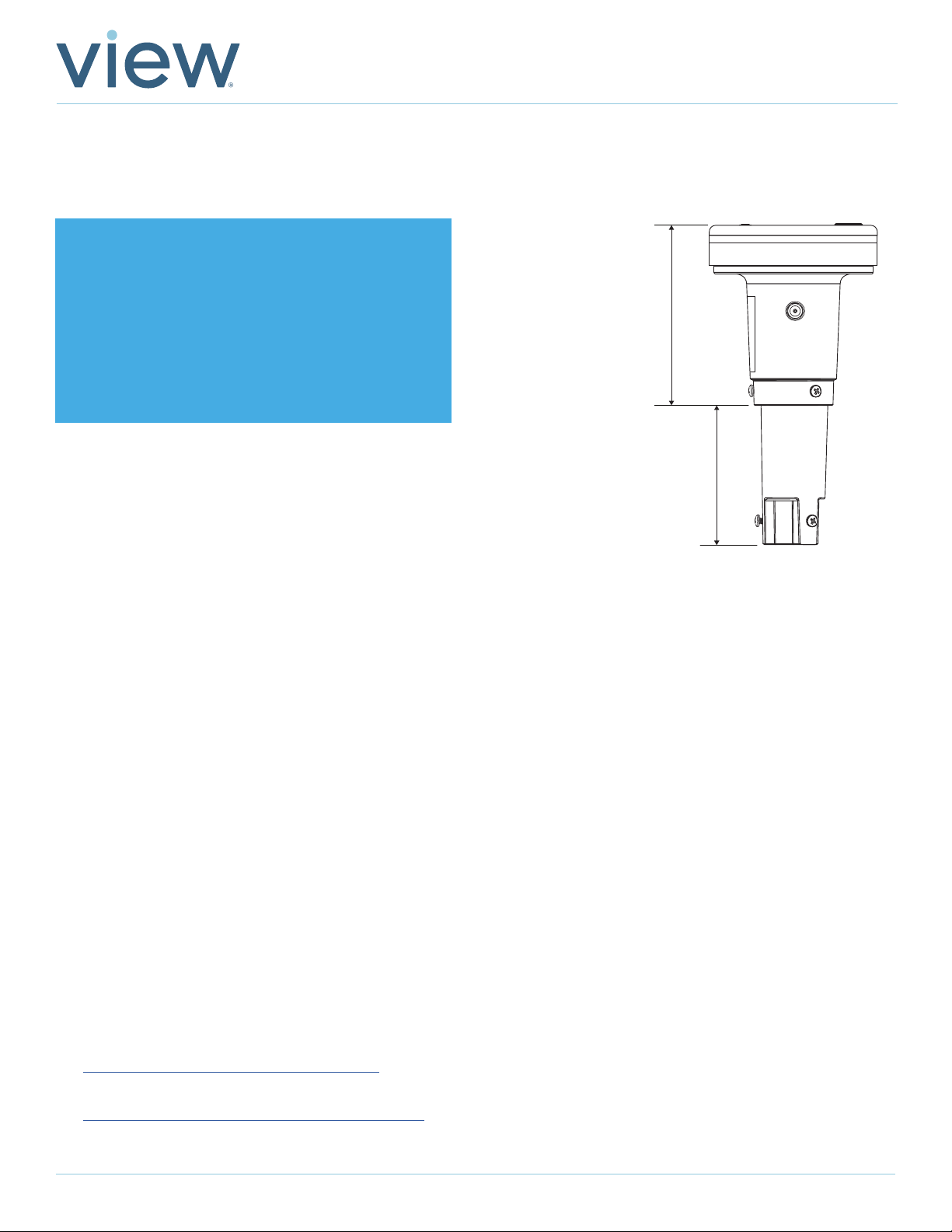
The Sky Sensor communicates to the View system and receives power via Power-over-Ethernet (PoE) utilizing midspan
Power Injector.
1. PoE voltage requirements: Class 0, 36 - 57 VDC. Powering device should be Type 1 and not higher.
2. Category CAT5 or above.
3. Maximum cable segment length is 328 feet (100 meters).
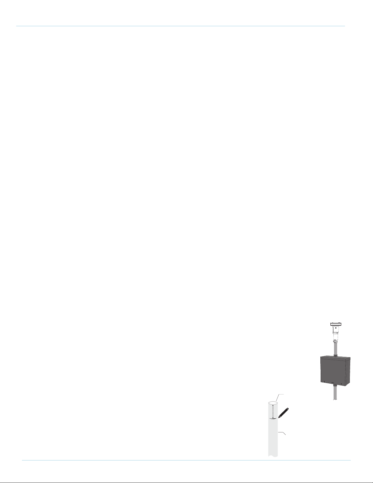
1 ¼”
½”
Rigid
Metallic
Tubing
Mark
Deburr
Sky Sensor Installation Guide
Mounting Requirements
1. Top of Sky Sensor shall be mounted at minimum 2-feet above the highest obstruction on the roof of the building.
Provide 360 degree unobstructed view horizontal, 200 degree vertical (10 degree below horizontal).
2. Ensure mounting height will not be obscured based on average snowfall.
3. Mounting system must be bonded to building ground.
4. Verify mounting location in field with building owner.
5. Mounting system and mast needs to comply with local building codes and withstand high winds based on
geographical location.
Work Performed By:
Low-Voltage Electrician
Installation
Step 1: Install the Mast
1. When selecting a location to install the mast, ensure the Sky Sensor will not be obstructed to the sky or the horizon.
Ensure it’s mounted high enough that snow accumulation or falling debris such as leaves will not cover the Sky
Sensor once mounted on top of the mast.
2. Using 1/2” Rigid Metallic Tubing (RMT), mount the mast to the top of the roof using standard industry procedures.
Ensure the installation complies with local building ordinances. Note: Do not use EMC/EMT.
3. Mount must be bonded to the building ground.
4. Deburr the top of the mast so that a cable can be routed through the mast and not cause damage to
the cable.
5. Install NEMA 3S weather rated pull box to the top of the mast (no smaller than 10 x 10 x 6”, no less than
NEMA 3S rating), 4-Square Bell box also acceptable, see page 7 for Best Known Methods.
6. Add additional conduit to top of pull box for the sky sensor base assembly, make a
mark 1 1/4” from the top of this conduit as shown. Make sure the top of the sky
sensor is 2-feet above the highest obstruction on the roof.

3Rev 07 | Oct 2020 © 2020 View, Inc. All rights reserved.
Sky Sensor Base
and mark should
align
Sky Sensor Installation Guide
Step 2: Install Sky Sensor Base and Route Ethernet Cable:
1. Using a Phillips head screw driver, loosen the three set screws at the base of the Sky
Sensor. This will allow you to slide the base down onto the mast.
2. Feed the View supplied 50-foot CAT5 Ethernet cable down the mast into the building
space until the end of the cable with the dust cap is sitting inside the Sky Sensor Base on
top of the mast. Use caution to ensure you don’t damage the RJ45 connector. Leave the
metal dust cap on the end of the Ethernet cable during this step.
3. Leave full courtesy loop inside the pull box for future service work.
4. Slide the Sky Sensor base down onto the mast and ensure the bottom of the Sky Sensor
Base lines up with the mark that you made 1 1/4” from the top. If the two align, this
indicates that the Mast is fully inserted into the Sky Sensor.
5. Hand tighten the three set screws until firmly secured to the mast. Note: Do not over
tighten and strip the screws. Do not use power tools.
6. Using standard CAT5 Ethernet tester, confirm Ethernet is working.

4Rev 07 | Oct 2020 © 2020 View, Inc. All rights reserved.
Sky Sensor Installation Guide
Step 3: Connecting to View Control Panel
1. Connect the 50 FT ethernet cable to either the control panel switch or a facility
ethernet switch depending on the network configuration. Note: If your data drop
can’t be reached by the provided CAT5 cable, you can use the supplied RJ45
Coupler (L-COM) to extend the cable. This Ethernet extension cable must be
shielded. The coupler must be earth grounded. If the coupler is placed outside it
must be in an enclosure. The maximum CAT5 cable length supported by sky sensor
is 328 FT total (including the 50 ft length supplied). *See also addendum at the end
of this document.
Before After
Step 4: Prepare Sky Sensor Body for Installation
1. Using a Phillips screw driver, loosen the three set screws on the Sky Sensor Body.
2. Remove the dust cap on the bottom inside of the Sky Sensor Body.

5Rev 07 | Oct 2020 © 2020 View, Inc. All rights reserved.
Sky Sensor Installation Guide
Step 5: Connect Data Cable to Sky Sensor
1. Remove the dust cap from the CAT5 ethernet cable inside the Sky Sensor
Base on the mast.
2. Align the RJ 45 connector and the keying feature (see below) and small
hole on the bottom of the Sky Sensor. Once aligned, carefully press the
two together and hand-tighten the black colored sleeve securely to the
base of the Sky Sensor.
3. Ensure the mid span injector is installed and then test the sensor
connectivity by connecting your laptop to the “network” (vs “network +
power”) side of the midspan injector. This test can also be done from the
control panel by plugging a laptop into one of the available Ethernet jacks
on the top of the control panel (any jack other than J17).
Keying Feature Sealing Surface
1.38
[34.9]
Step 6: Mount the Sky Sensor
1. With the RJ45 connected to the Sky Sensor, place it onto the Sky Sensor Base.
2. Using a Phillips screw driver, tighten the three set screws on the Sky Sensor to
secure it to the Sky Sensor base. The screw will thread into the base until the
head of the screw bottoms-out on the wall of the sensor; it does not need to
be tightened past this point.

6Rev 07 | Oct 2020 © 2020 View, Inc. All rights reserved.
Sky Sensor Installation Guide
Sensor
Sensor
Sensor
Sensor
Gore Patch
Step 7: Test the Sky Sensor
1. Option A: If the Sky Sensor is connected directly to the Control Panel or is connected to a customer network that
is connected to the Control Panel, then use an unused Ethernet port on the Control Panel (not J17) and continue
to step 2.
Option B: If it’s not terminated to customer network, utilize POE and continue to step 2.
Option C: If it is connected to customer network but not to our Control Panel, then connect to customer network
and continue to step 2.
2. Test the connection to the sensor by using a laptop equipped with a RJ45 connection and a web browser. Note:
Without a DHCP server, the sensor will default to a static IP address of 10.50.80.150. If working with customer
DHCP, MAC Address must start with 60:84:3b.
3. With the Ethernet cable connected to the laptop, configure the laptop to be on the same IP subnet (typically
10.50.80.252) and open a web browser to the sensors IP address.
4. Once testing is complete, plug-in the Ethernet cable to the permanent data drop.
Step 8: Final Operation Preparation
1. Using an optical cleaning wipe,
clean the sensors on the sides
and top of the Sky Sensor.
Ensure all sensors are free
of dust, debris, and oils from
fingers.
2. Ensure the Gore Patch on
the side of the sensor is not
damaged, taped over or covered
by silicone.

7Rev 07 | Oct 2020 © 2020 View, Inc. All rights reserved.
Sky Sensor Installation Guide
Best Known Methods

8Rev 07 | Oct 2020 © 2020 View, Inc. All rights reserved.
Sky Sensor Installation Guide
Addendum - Sky Sensor Grounding Coupler Installation
This document covers installation of the LCOM Part Number HGLN-CAT6J Lightning Protector when site conditions
prevent the 50-foot cable provided with the Sky Sensor to directly terminate to the View control panel.
Introduction
The View Sky Sensor is provided with a 50-foot shielded twisted pair (STP) CAT5 ethernet cable to connect the sensor
to the control panel. In the case where the Sky Sensor cable does not directly connect to the control panel, then a
ground coupler should be used.
Procedure
Refer to the picture:
• The two Ethernet jacks on the top of the protector are not specific, the cable from the Sky Sensor can be plugged into
either of the jacks.
• Mount the protector to a solid object, a wall or Telecom rack with the four mounting ears and suitable self-tapping
screws.
• Crimp the provided ring lug on a suitable length (site specific) 14AWG THHN green or green/yellow wire (not provided
by View) to bond the protector to a designated earth ground. Typically, telecom racks used in data closets are grounded,
as are conduit fitting and boxes. If there is any doubt on the proper facility ground point, consult with the electrician
on site.
• Connect the View provided Sky Sensor cable to one of the RJ45 jacks.
• Connect the extension Ethernet CAT6 cable (UTP or STP) to the other port on the protector and then to the View
control panel.
• Verify connectivity of the sensor to the panel.
Other manuals for Sky Sensor
1
Table of contents
Other View Accessories manuals
Popular Accessories manuals by other brands

Nice
Nice volo Instructions and warnings for fitters

Opticon
Opticon EBS-40 quick start guide

E+E Elektronik
E+E Elektronik EE355 user manual

Lightspeed
Lightspeed 955 Access SET UP AND DAILY OPERATION INSTRUCTIONS

Belson
Belson DUETTO STYLER MH2241 Use and care book

Etherma
Etherma PA Installation and usage instructions