View Sky Sensor User manual

1 of 12
Installation Guide
QDM-05-000045
Rev 8 | July 2022 ©2022 View, Inc.
Sky Sensor Installation Guide
Work Performed By:
Low-Voltage Electrician
Sky Sensor Body
Sky Sensor Base
The roof-mounted Sky Sensor
provides external light level data
and infrared temperature data to the
View system to allow optimization
of tint levels for each zone. The
assembly includes the Sky Sensor
with a 4 ft. length of CAT5 Ethernet
cable attached.
Package Includes
1. Sky Sensor Assembly
• View Net (P/N: VN-SKY)
• CSS (P/N: 005-101418)
2. Sky Sensor Installation Kit (P/N: VN-SMK)
Tools and Materials Required
1. 3/4” Rigid Metallic Tubing (RMT) for roof mast, brackets, ashing and sealant.
2. #2 Phillips screwdriver
3. Cutting, Drilling and Deburring tools.
4. Wire stripping tools.
5. Wrenches.
6. Grounding wire: 12 AWG THHN green or green/yellow
7. 300 ft Unshielded Plenum CAT5 ethernet cable spool, modular connectors and crimping tool.
8. Standard Junction box (10 x 10 x 6”), CSS Only
9. CAT5 Ethernet tester
Additional Supporting Documentation
1. Sky Sensor Data Sheet - QDM-02-000247
2. CP5.5 Data Sheet - QDM-02-000244
3. CP5.0 Data Sheet - QDM-02-000219
4. CP2.0 Data Sheet - QDM-02-000033

2Rev 8 | July 2022 © 2022 View, Inc. All rights reserved.
Sky Sensor Installation Guide
System Requirements
The Sky Sensor communicates to the View System and receives power via PoE. In CP 3.0 or lower this occurs via
external PoE device. CP 5.0 or higher provides PoE direct from the switches.
1. PoE voltage requirements: Class 0, 36 - 57 VDC. Powering device should be Type 1 and not higher.
2. Category CAT5 unshielded cable or above.
3. For CAT5 cable, the maximum cable length is 328 feet (100 meters).
Mounting Requirements
1. Sky Sensor shall be mast mounted on the roof.
2. Elevate sensor height as required to obtain clear line of sight
to the horizon for optimum system performance.
3. Top of Sky Sensor shall be mounted at minimum 2-feet above
the highest obstruction on the roof of the building. Provide
360 degree unobstructed view horizontal.
4. Ensure mounting height will not be obscured based on
average snowfall.
5. Mounting system must be bonded to building ground at the
location of electrical junction box.
6. Verify mounting location in eld with building owner and View
Interconnect Drawings.
7. Mounting system and mast needs to comply with local building
codes and withstand high winds based on geographical
location.
8. If possible, for a building with a lightning arrestor system,
the Sky Sensor and electrical junction box to be installed a
minimum of 5-10 meters from any of the lightning rods.
9. For a building with a singular lightning tower, the Sky Sensor
should be installed 2 ft. lower the highest point of the
lightning tower.
10. When installed, the electrical junction box (EJB) bottom
surface needs to be at least 1 ft above ground level.

3Rev 8 | July 2022 © 2022 View, Inc. All rights reserved.
Sky Sensor Installation Guide
1 ¼”
½”
Rigid
Metallic
Tubing
Mark
Deburr
Installation
Step 1: Install the Mast
1. Using 3/4” Rigid Metallic Tubing (RMT), mount the mast to the top of the roof using standard industry
procedures. Minimum length of the RMT must be 1 ft above the roung. Ensure the installation complies
with local building ordinances. Do not use EMC/EMT.Do not use EMC/EMT.
2. Deburr the top of the mast so that a cable can be routed through the mast and not cause damage to the
cable.
3. Install electrical junction box (EJB) to the top of the mast (see Best Known Methods).
4. Add included pipe to top of the EJB for the sky sensor base assembly, make a mark 1-1/4” from the top
of this pipe as shown. Make sure the top of the sky sensor is 2-feet above the highest obstruction on the
roof.
5. EJB must be bonded to the building ground. Use the provided lug nut on the bottom of the EJB.
6. In case local regulations or windloads dictate, the EJB has mounting ears to attach to a structure. Use
3/4” hardware to secure when necesary.

4Rev 8 | July 2022 © 2022 View, Inc. All rights reserved.
Sky Sensor Installation Guide
Sky Sensor Base
and mark should
align
Step 2: Install Sky Sensor Base and Route Ethernet Cable
1. Using a Phillips head screwdriver, loosen the three set screws at the base of the
Sky Sensor. This will allow you to slide the base down onto the mast.
2. Feed the View supplied 4-foot CAT5 Ethernet cable into the Electrical Junction
Box (EJB) until the end of the cable with the dust cap is sitting inside the Sky
Sensor Base on top of the mast. Use caution to ensure you don’t damage the RJ45
connector. Leave the metal dust cap on the end of the Ethernet cable during this
step.
3. Slide the Sky Sensor base down onto the ½” galvanized steel pipe and ensure the
bottom of the Sky Sensor Base lines up with the mark that you made 1-1/4” from
the top. If the two align, this indicates that the ½” pipe is fully inserted into the
Sky Sensor.
4. Hand tighten the three set screws until rmly secured to the ½” pipe. Note: Do
not over tighten and strip the screws. Do not use power tools.
5. Using standard CAT5 Ethernet tester, test end-to-end to conrm Ethernet is not
damaged after installation through the mast. Additional testing is required upon
nal installation.
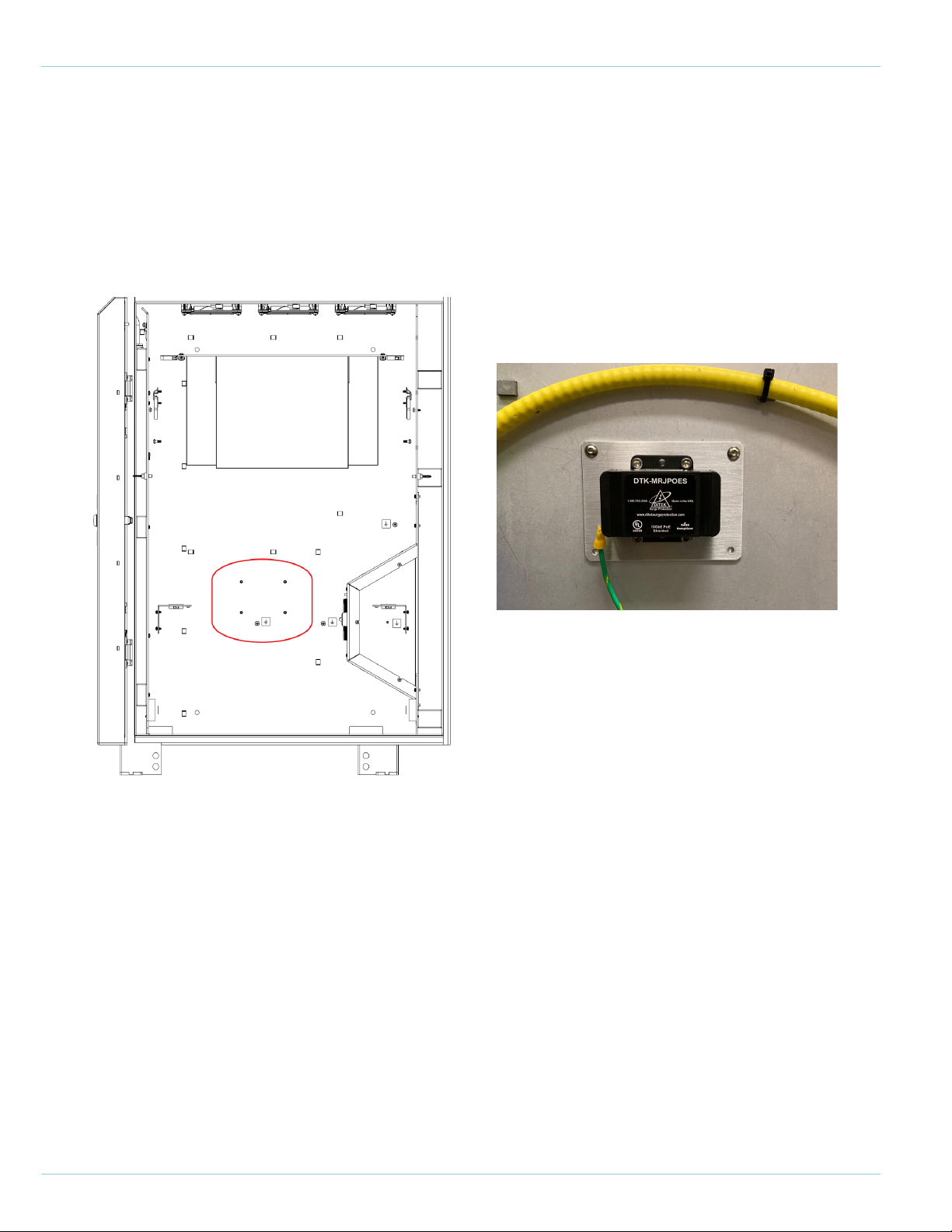
6. Connect the Sky Sensor cable to the RJ45 Jack labeled as OUT on the EJB surge
protector. The top connector on the surge protector is next to the grounding stud,
use image for reference. NOTE: Connecting the Sky Sensor to the incorrect port
will result in damage to the Sensor.

5Rev 8 | July 2022 © 2022 View, Inc. All rights reserved.
Sky Sensor Installation Guide
1. Install Standard Junction Box a maximum of 10 ft. from Control Panel
2. Mount the surge protector to the inside of the Standard Junction box with the four suitable self-tapping screws.
3. Crimp the provided ring lug on a suitable length (site specic) 12AWG THHN green or green/yellow wire (not
provided by View) to bond the protector to a designated earth ground. If there is any doubt on the proper facility
ground point, consult with the electrician on site.
4. Route the ethernet cable from the EJB to the Standard Junction Box. Connect the cable to the RJ45 Jack labeled
as ININ of each surge protector.. Note: Test the cable like in step 2.5.
5. Connect the extension Ethernet CAT6 unshielded cable (UTP) from the RJ45 Jack labeled as OUT to port J18
on top of the Control Panel. Verify that the other side of the J18 feed-thru couple is connected to the Data+PoE
port of the Tripp-Lite PoE injector inside the control panel.
Step 3 CSS: Connecting to Grounding Coupler and View Control Panel (1.0-3.0)

6Rev 8 | July 2022 © 2022 View, Inc. All rights reserved.
Sky Sensor Installation Guide
1. Remove the Telco Rack from the CP5.0
2. Drill holes on the CP5.0 as shown bellow.
3. Mount the Surge Protector Adapter Plate on the CP5.0 and secure using self-taping screws.
4. Mount the Surge Protector on the adapter plate as shown. Use the provided screws.
5. Using the provided 12AWG THHN green or green/yellow wire ground the surge protector to the CP5.0 as shown.
Note: Preferably ground to a single ground stud. Use the provided star washer.
6. Route the ethernet cable from the EJB to the CP through the CP’s overhead cable entry slot as shown. Connect
the cable to the RJ45 Jack labeled as ININ of each surge protector.. Note: Test the cable like in step 2.5.
7. Connect the extension Ethernet CAT6 unshielded cable (UTP) from the RJ45 Jack labeled as OUT to Port 7 of
the NCS#2 switch in the Telco Rack.
Step 3 View Net CP5.0: Connecting to Grounding Coupler and View Control Panel
7Rev 8 | July 2022 © 2022 View, Inc. All rights reserved.
Sky Sensor Installation Guide
1. Remove the Telco Rack from the CP5.5.
2. Mount the Surge Protector Adapter Plate on the CP5.5 and secure with the provided screws.
3. Mount the Surge Protector on the adapter plate and secure with the provided screws as shown.
4. Using the provided 12AWG THHN green or green/yellow wire ground the surge protector to the CP5.5 as shown.
5. Route the ethernet cable from the EJB to the CP through the CP’s overhead cable entry slot as shown. Connect
the cable to the RJ45 Jack labeled as ININ of each surge protector.. Note: Test the cable like in step 2.5.
6. Connect the extension Ethernet CAT6 unshielded cable (UTP) from RJ45 Jack labeled as OUT to Port 7 of the
NCS switch in the Telco Rack.
Step 3 View Net CP5.5: Connecting to Grounding Coupler and View Control Panel
8Rev 8 | July 2022 © 2022 View, Inc. All rights reserved.
Sky Sensor Installation Guide
Before After
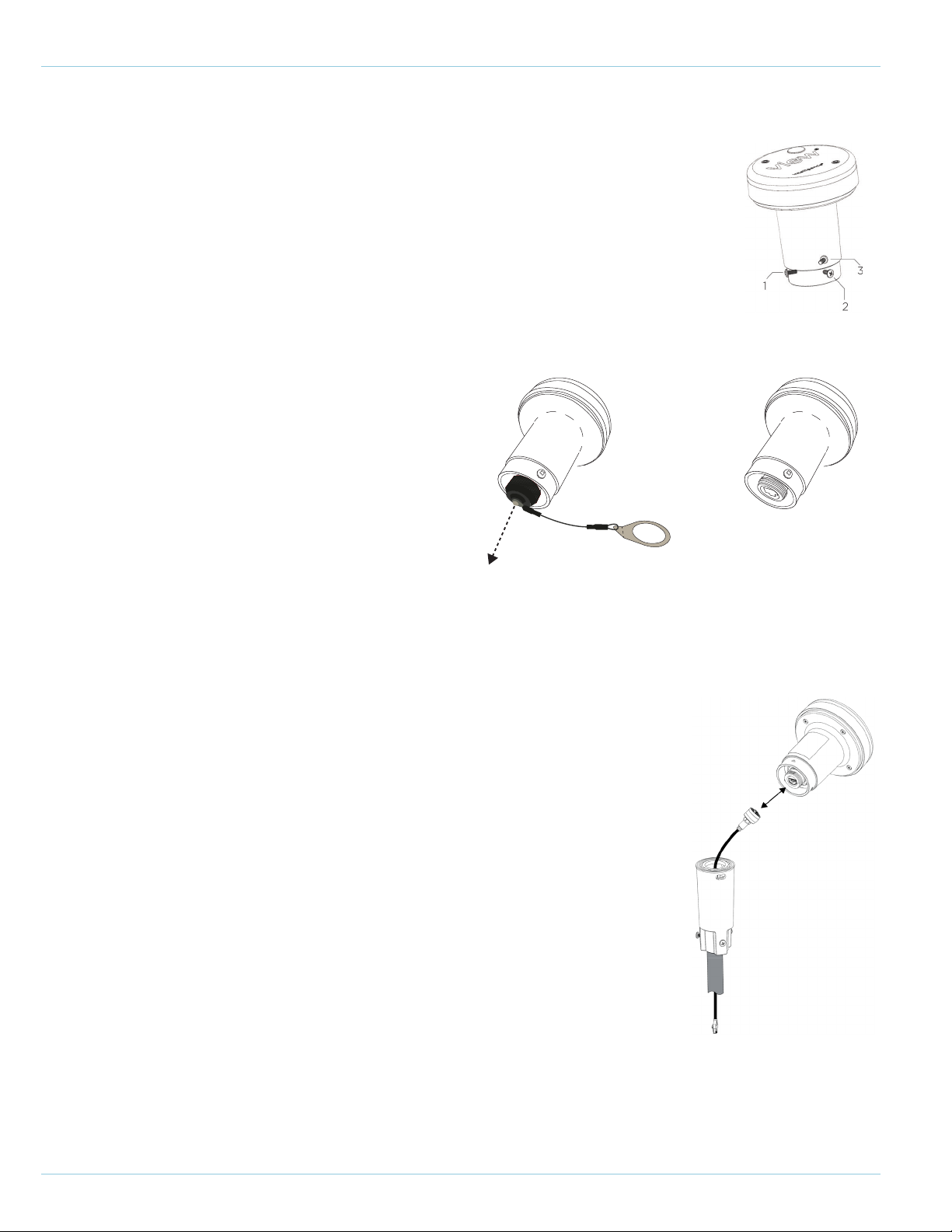
1. Using a Phillips screwdriver, loosen the three set screws on the Sky Sensor Body.
2. Remove the dust cap on the bottom inside of the Sky Sensor Body.
Step 5: Connect Data Cable to Sky Sensor
1. Remove the dust cap from the CAT5 ethernet cable inside the Sky Sensor
Base on the mast.
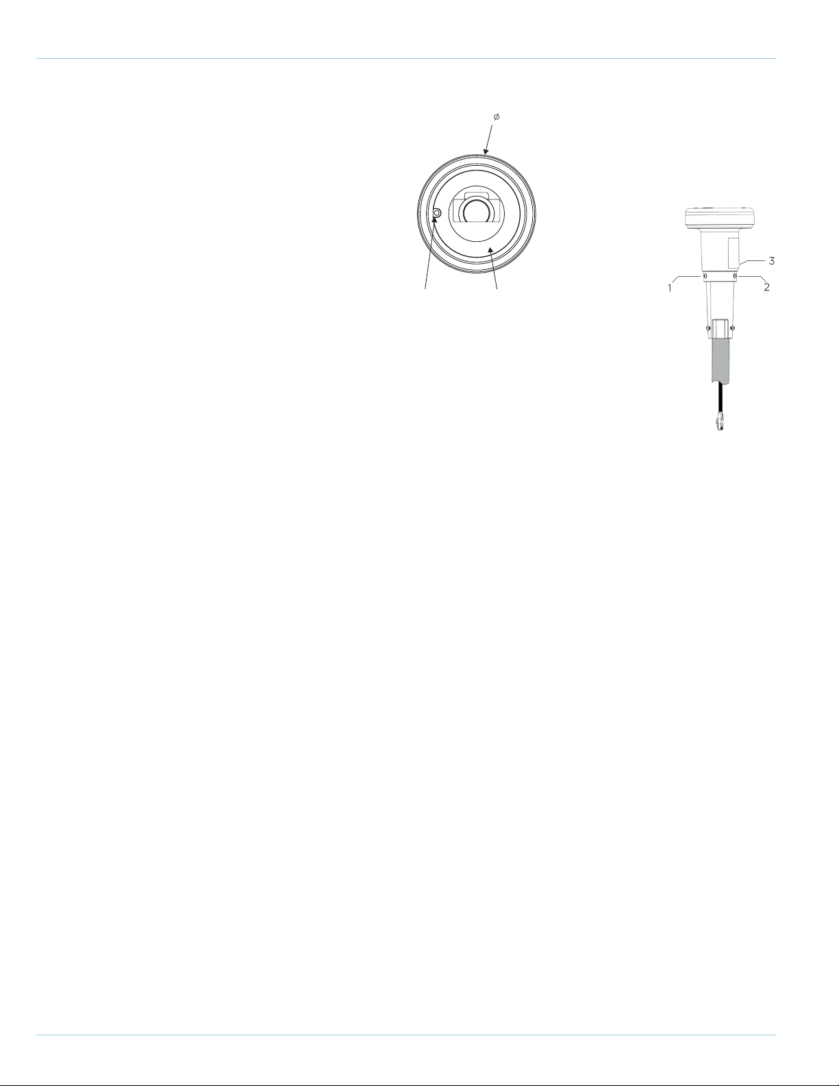
2. Align the RJ 45 connector and the keying feature (see below) and small
hole on the bottom of the Sky Sensor. Once aligned, carefully press the two
together and hand-tighten the black colored sleeve securely to the base of the
Sky Sensor.
Step 4: Prepare the Sky Sensor Body for installation
9Rev 8 | July 2022 © 2022 View, Inc. All rights reserved.
Sky Sensor Installation Guide
Keying Feature Sealing Surface
1.38
[34.9]
Step 6: Mount the Sky Sensor
1. With the RJ45 connected to the Sky
Sensor, place it onto the Sky Sensor Base.
2. Using a Phillips screwdriver, tighten the three set screws on the Sky Sensor to secure
it to the Sky Sensor base. The screw will thread into the base until the head of the
screw bottoms-out on the wall of the sensor; it does not need to be tightened past
this point.
Step 7: Sky Sensor Verication
1. Contact View Costumer Support to verify connectivity.

10Rev 8 | July 2022 © 2022 View, Inc. All rights reserved.
Sky Sensor Installation Guide
Sensor
Sensor
Sensor
Sensor
Gore Patch
Step 8: Final Operation Preparation
1. Using an optical cleaning wipe, clean the sensors on the sides and top of the Sky Sensor. Ensure all sensors
are free of dust, debris, and oils from ngers.
2. Ensure the Gore Patch on the side of the sensor is not damaged, taped over or covered by silicone.
Other manuals for Sky Sensor
1
Table of contents
Other View Accessories manuals


