Viewpro 12M HD IP User manual
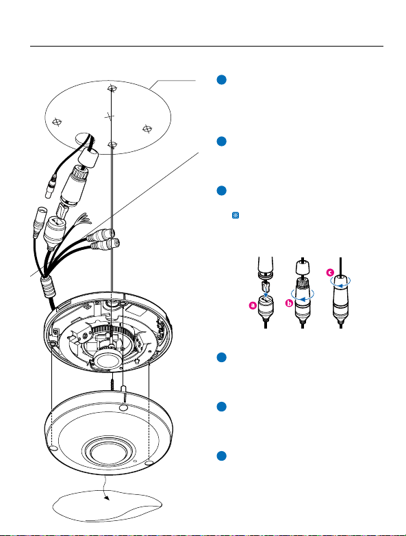
1Detach the camera’s cover dome from
the camera’s module by unscrewing
the three cover dome srews using
L-wrench.
2Use the camera or mountemplate
to mark and drill necessary holes in
the wall or ceiling.
3Pull wires through and make
c
Put the Lan cable into (a), then (b) will
be assembled thtly
step, (c) need to be assembled to (b)
without making any space.
4Using two(2) included screws, mount
and secure the camera to the
mounface.
5Secure the camera’s cover dome onto
the camera base to complete the
installa
6Detach the protrom the
dome cover.
1. Product & Accessories 2. Part Name 3. Disassemble the Camera 4. Installa
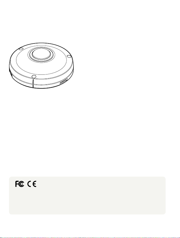
12M HD IP
Fisheye Outdoor Vandal Dome Camera
Quick Manual
G Ver. 1.2 / 2021.03
Before installing and using the camera, please read this manual carefully.
Be sure to keep it handy for future reference.
To disconnect power from the mains, pull out the mains cord plug. When install the product, ensure that the plug is easily
accessible.
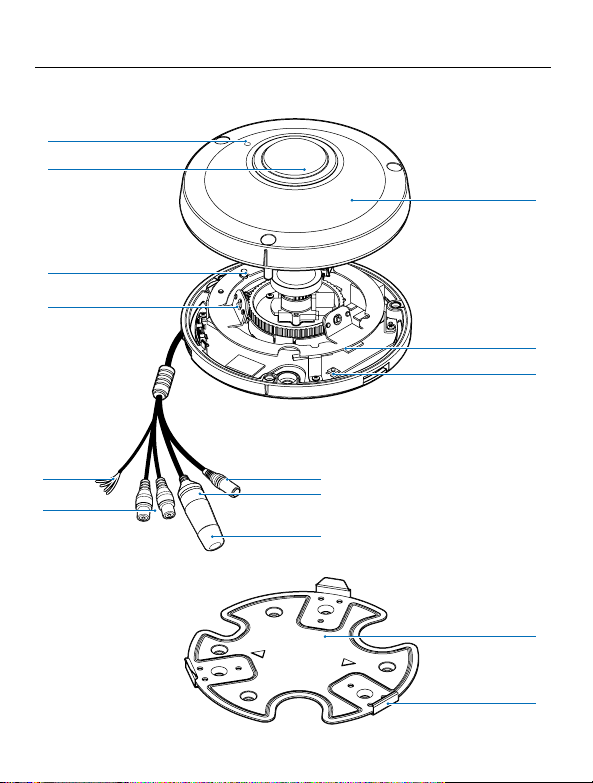
Camera
Cables
BOTTOM HOLE
GASKET
HOLE POINT
UPPER SENSOR
HOLE POINT
Template Sheet
This equipment has been tested and found to comply with the limits for a Class A digital device, pursuant to part 15 of the FCC
Rules. These limits are designed to provide reasonable prot against harmful interference when the equipment is operated in
a commercial environment. This equipment generates, uses, and can radiate radio frequency energy and, if not installed and used
in accordance with the ins manual, may cause harmful interference to radio communica Opera of this equipment
in a residen area is likely to cause harmful interference in which case the userwill be required to correct the interferenece at his
own expense.
Dome Cover
Illumina
Illumina
IR LED
Alarm In/Out
Audio In/Out
Window Cover
SD Card Slot
Reset Buon
DC Power Jack
RJ-45 Connector
Waterproof Cap
Before installing your camera, you have to read the following cau�ons.
1. You have to check whether the locacan bearve mes of the weight of your camera.
2. Don’tlet the cable to be caught in improperplace or the electric line cover to be damaged.
Otherwise it may cause abreakdown orre.
3. When installing your camera, don’tallow any person to approach the installate.
If you have any valuable things under the place, move them away.
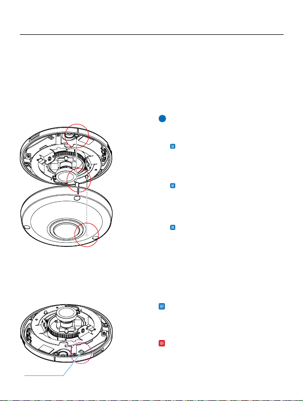
1Detach the dome cover by torx wrench
provided from boom case before
installacamera.
The camera includes a sensor at the
camera’s module. For the sensor to
roperly, the camera’s dome
includes a special hole the sensor.
When assembling the camera together,
please make sure the sensor hole in the
camera’s dome is pos on top of the
sensor on the camera’s module.
Be sure to assemble the dome cover
and boom case to match the case
outline.
Reset to the Factory Default
Press the reset buon for 5 seconds to
return the setup to the factory default.
Warning :
If you press the ‘Reset’ buon, you will
lose all seata. If needed, please,
make a note for further installa
Mount Plate
Plate Hook
Reset Buon
Mount Bolt & Nut
Template Sheet
for installaby Bolt & Nut
Mount Plate Quick Manual
Template Sheet
for installaby Plate
Waterproof cap &
Gasket
Torx Wrench
Screw &
Plas
Safety Informa Installarec
POWER
1. Use the power line ato the power cterminal.
Incomplete ccan cre.
2. Do not extend the adapter output cable. If you need to install the power cable
extension, please contact the service center.
3. Use insulated power for PoE connected external power.
INSTALLATION
1. It is recommended not to touch the lens when installing the product as the factory
ships with a focus adjustment completed during the manufacturing comple
2. Avoid installing cameras facing bright lights like sunlight. Causes damage to the
image sensor.
3. Make sure it safe and securely when installing camera on the wall or ceilling. This
can cause injury by the fall.
4. Do not ccameras to one adapter. Excess capacity causes abnormal
heare.
5. Wear protve gloves when installing/uninstalling the camera. This causes burns
caused by high temperature on the surface of the product.
6. Don't drop or shock the product. Please stay away from places where vibra
severe or magnet types are present.
7. Install it in a well-venated place. This can cre and failure.
CLEANING
1. Wipe the contaminated surfry cloth or wery cloth
to prevent water frowing, then wipe the contaminated area.
1. The baery (baery pack or equipped baery) must not be exposed to excessive
heat such as sunlighre, etc.
2. Do not disassemble the camera at your discre
3. If you forcefully install the product with excessive forcan damage
the camera.
4. Do notpunch orshake the camera and be careful not to damage the camera with
careless storage or malfunc.
5. Be careful not to install the camera in a rainy or humid place, and do not leave it in a
wet place.
6. Installing or using the product in water can cause serious product failure.
7. Do not install the product if there is chemical or vapor in the place where the
product is installed, or if it can be generated.
8. Be careful not to get chemicals on the surface of the product when installing the
product. Chemical solvents such as cleaning agents and adhesive components can
cause fatal damage to the surface of the product.
9. Do not install it near the kitchen or cooking table as edible oil such as soybean oil
can also cause product damage and deformacan cause product damage.
10. Be careful not to get foreign substances on the Micro SD card terminal. If there is
any foreign subst
11. Data will not be saved at the end of the life of the Micro SD card. In this case,
purchase a new Micro SD card.
12. Moisture may occur in the glass of the camera when the new product box is opened
(or when the prgenerated moisture is removed by a
Gore vent aached to the camera within hours of the power c
13. For products enclosed with a desiccant or card-type absorbent, please install it
according to the manual.
14.
by the manufacturer, or sold with the apparatus.
15.
WARNINGS : Serious injury or death may be caused
if any of these warnings are neglected.
BATTERY
1. There is a risk of explosion if the baery is incorrectly replaced. The baery should
be replaced only with the same baery.
2. Used baeries must be disposed of according to local regulaaery
manufacturer's insre or in a hot oven, or mechanically
crushing and cuay cause an explosion.
3. Leaving the baery in a very high temperature orlow air pressure environment may result
in an explosion orleakammable liquids or gases.
POWER
1. Use only standardized adapters wrien in the manual. Incorrect c
power source can cre, electric shock, or failure.
2. If there is smoke or a strange smell from the power source, disconnect the power
immediately and contact the service center or purchasing oyou conto
use it as it is, it can cre and electric shock.
3. Disconnect the power plugfrom the outlet before connecg to the power terminal block.
INSTALLATION
1. Install it according to the temperature and humidity environment suitable for the
prcarwise, it can cre and electric shock.
2. Thunder and lightning can cause problems with the camera. When installing, be
careful to minimize damage caused by lightning such as grounding.
3. Do not place cve materials (drivers, coins, metal sks, etc.) and water-
containers on the camera. It causes injuries caused by re, electric shock, and falling.
4. If you want to move the installed product, turn othe power and move itor reinstall it.
Otherwise, it can cre and electric shock.
These instruc�ons are intended to ensure that the user can use the product correctly
to avoid danger or property loss.
If the product is not func�oning properly or damaged, contact the service center or
purchasing office.
CAUTIONS : Injury or equipment damage may be caused
if any of these cre eglected.
5. Do not install it in places where there is a lot of moisture, dust, soot, etc. It causes
re and electric shock.
6. Avoid places where direct sunlight comes in or where heat comes out, such as
heacre and electric shock.
CLEANING
1. Do not spray water directly on each part of the product when cleaning. It cre
and electric shock.
CAUTION : Risk of explosion if baery is replaced by an incorrect type.
Dispose of used of used baeries according to the ins
ATTENTION : Il y a risqued'explosion si labaerie est remplaéeparune baerie de type incorrect.
Mere au rebut les baeries usagees conformément aux ins
1Detach the camera’s cover dome from
the camera’s module by unscrewing
the three cover dome srews using
L-wrench.
2Use the camera or mountemplate
to mark and drill necessary holes in
the wall or ceiling.
3Pull wires through and make
c
Put the Lan cable into (a), then (b) will
be assembled thtly
step, (c) need to be assembled to (b)
without making any space.
4Using two(2) included screws, mount
and secure the camera to the
mounface.
5Secure the camera’s cover dome onto
the camera base to complete the
installa
6Detach the protrom the
dome cover.
1. Product & Accessories 2. Part Name 3. Disassemble the Camera 4. Installa
12M HD IP
Fisheye Outdoor Vandal Dome Camera
Quick Manual
G Ver. 1.2 / 2021.03
Before installing and using the camera, please read this manual carefully.
Be sure to keep it handy for future reference.
To disconnect power from the mains, pull out the mains cord plug. When install the product, ensure that the plug is easily
accessible.
Camera
Cables
BOTTOM HOLE
GASKET
HOLE POINT
UPPER SENSOR
HOLE POINT
Template Sheet
This equipment has been tested and found to comply with the limits for a Class A digital device, pursuant to part 15 of the FCC
Rules. These limits are designed to provide reasonable prot against harmful interference when the equipment is operated in
a commercial environment. This equipment generates, uses, and can radiate radio frequency energy and, if not installed and used
in accordance with the ins manual, may cause harmful interference to radio communica Opera of this equipment
in a residen area is likely to cause harmful interference in which case the userwill be required to correct the interferenece at his
own expense.
Dome Cover
Illumina
Illumina
IR LED
Alarm In/Out
Audio In/Out
Window Cover
SD Card Slot
Reset Buon
DC Power Jack
RJ-45 Connector
Waterproof Cap
Before installing your camera, you have to read the following cau�ons.
1. You have to check whether the locacan bearve mes of the weight of your camera.
2. Don’tlet the cable to be caught in improperplace or the electric line cover to be damaged.
Otherwise it may cause abreakdown orre.
3. When installing your camera, don’tallow any person to approach the installate.
If you have any valuable things under the place, move them away.
1Detach the dome cover by torx wrench
provided from boom case before
installacamera.
The camera includes a sensor at the
camera’s module. For the sensor to
roperly, the camera’s dome
includes a special hole the sensor.
When assembling the camera together,
please make sure the sensor hole in the
camera’s dome is pos on top of the
sensor on the camera’s module.
Be sure to assemble the dome cover
and boom case to match the case
outline.
Reset to the Factory Default
Press the reset buon for 5 seconds to
return the setup to the factory default.
Warning :
If you press the ‘Reset’ buon, you will
lose all seata. If needed, please,
make a note for further installa
Mount Plate
Plate Hook
Reset Buon
Mount Bolt & Nut
Template Sheet
for installaby Bolt & Nut
Mount Plate Quick Manual
Template Sheet
for installaby Plate
Waterproof cap &
Gasket
Torx Wrench
Screw &
Plas
Safety Informa Installarec
POWER
1. Use the power line ato the power cterminal.
Incomplete ccan cre.
2. Do not extend the adapter output cable. If you need to install the power cable
extension, please contact the service center.
3. Use insulated power for PoE connected external power.
INSTALLATION
1. It is recommended not to touch the lens when installing the product as the factory
ships with a focus adjustment completed during the manufacturing comple
2. Avoid installing cameras facing bright lights like sunlight. Causes damage to the
image sensor.
3. Make sure it safe and securely when installing camera on the wall or ceilling. This
can cause injury by the fall.
4. Do not ccameras to one adapter. Excess capacity causes abnormal
heare.
5. Wear protve gloves when installing/uninstalling the camera. This causes burns
caused by high temperature on the surface of the product.
6. Don't drop or shock the product. Please stay away from places where vibra
severe or magnet types are present.
7. Install it in a well-venated place. This can cre and failure.
CLEANING
1. Wipe the contaminated surfry cloth or wery cloth
to prevent water frowing, then wipe the contaminated area.
1. The baery (baery pack or equipped baery) must not be exposed to excessive
heat such as sunlighre, etc.
2. Do not disassemble the camera at your discre
3. If you forcefully install the product with excessive forcan damage
the camera.
4. Do notpunch orshake the camera and be careful not to damage the camera with
careless storage or malfunc.
5. Be careful not to install the camera in a rainy or humid place, and do not leave it in a
wet place.
6. Installing or using the product in water can cause serious product failure.
7. Do not install the product if there is chemical or vapor in the place where the
product is installed, or if it can be generated.
8. Be careful not to get chemicals on the surface of the product when installing the
product. Chemical solvents such as cleaning agents and adhesive components can
cause fatal damage to the surface of the product.
9. Do not install it near the kitchen or cooking table as edible oil such as soybean oil
can also cause product damage and deformacan cause product damage.
10. Be careful not to get foreign substances on the Micro SD card terminal. If there is
any foreign subst
11. Data will not be saved at the end of the life of the Micro SD card. In this case,
purchase a new Micro SD card.
12. Moisture may occur in the glass of the camera when the new product box is opened
(or when the prgenerated moisture is removed by a
Gore vent aached to the camera within hours of the power c
13. For products enclosed with a desiccant or card-type absorbent, please install it
according to the manual.
14.
by the manufacturer, or sold with the apparatus.
15.
WARNINGS : Serious injury or death may be caused
if any of these warnings are neglected.
BATTERY
1. There is a risk of explosion if the baery is incorrectly replaced. The baery should
be replaced only with the same baery.
2. Used baeries must be disposed of according to local regulaaery
manufacturer's insre or in a hot oven, or mechanically
crushing and cuay cause an explosion.
3. Leaving the baery in a very high temperature orlow air pressure environment may result
in an explosion orleakammable liquids or gases.
POWER
1. Use only standardized adapters wrien in the manual. Incorrect c
power source can cre, electric shock, or failure.
2. If there is smoke or a strange smell from the power source, disconnect the power
immediately and contact the service center or purchasing oyou conto
use it as it is, it can cre and electric shock.
3. Disconnect the power plugfrom the outlet before connecg to the power terminal block.
INSTALLATION
1. Install it according to the temperature and humidity environment suitable for the
prcarwise, it can cre and electric shock.
2. Thunder and lightning can cause problems with the camera. When installing, be
careful to minimize damage caused by lightning such as grounding.
3. Do not place cve materials (drivers, coins, metal sks, etc.) and water-
containers on the camera. It causes injuries caused by re, electric shock, and falling.
4. If you want to move the installed product, turn othe power and move itor reinstall it.
Otherwise, it can cre and electric shock.
These instruc�ons are intended to ensure that the user can use the product correctly
to avoid danger or property loss.
If the product is not func�oning properly or damaged, contact the service center or
purchasing office.
CAUTIONS : Injury or equipment damage may be caused
if any of these cre eglected.
5. Do not install it in places where there is a lot of moisture, dust, soot, etc. It causes
re and electric shock.
6. Avoid places where direct sunlight comes in or where heat comes out, such as
heacre and electric shock.
CLEANING
1. Do not spray water directly on each part of the product when cleaning. It cre
and electric shock.
CAUTION : Risk of explosion if baery is replaced by an incorrect type.
Dispose of used of used baeries according to the ins
ATTENTION : Il y a risqued'explosion si labaerie est remplaéeparune baerie de type incorrect.
Mere au rebut les baeries usagees conformément aux ins

8. IP Installer
5. Installant Plate 6. Installant Bolt & Nut 7. Cabling
Template Sheet 1Detach the camera’s cover dome from
the camera’s module by unscrewing
the three cover dome screws.
2Using the metal mount plate, mark
and drill the necessary holes in the
wall or ceiling.
3Pull wires through and make
c
4Using the three (3) included screws,
mount and secure the camera to the
wall or ceiling.
5Aach the camera base to the metal
mount by snapping it into the place
using the two metal handles.
6Secure the camera’s cover dome onto
the camera base to complete the
installa
7Detach the protrom the
dome cover.
1Using the template sheet, make and
drill the cabling holes on the wall/
ceiling.
2Secure the two long mounrews
to the camera’s base.
3Pass the wires through the mount
bracket and make all necessary
c
4Mount the camera to the moun
surface by using the 2 moun
Rotate the locking discs over the
screws uncamerhtly
from the mounface.
5Secure the camera’s cover dome onto
the camera base to complete the
installa
6Detach the protrom the
dome cover.
1Power Connec�on
Please, check the voltage and current
capacity of rated power carefully.
2Network Connec�on
3Audio In
Connect the ‘Audio In’ cable of the
camera to the device like microphone.
4Audio Out
Connect the ‘Audio Out’ cable of the
camera to device like speaker.
Audio Out supports only RTSP Back
It plans to make it
available on the web later.
5Alarm Out
It connects to the alarm lights, siren or
lamps and the sensor types are normal
open and normal close.
Cable of the alarm output device
should connect to DO1(N.O.) and DO1
COM of the cable slot.
6Alarm In
Cable of the sensor/alarm input device
should connect to Yellow and White
line of the Alam cable.
1. Using a PoE-Enabled Switch
The Camera is PoE-compliant, allowing
transmission of power and data viaasingle
Ethernet cable.
PoE eliminates the need for the dierent
cables used to power, record, or control
the camera.
Follow the illustraow to connect
the camera to a PoE-enabled switch using
an Ethernet cable.
2. Using a Non-PoE Switch
If a PoE-enabled switch is not used, use a
power adaptor for power transmission and
non-PoE switch for data transmission.
Follow the illustraow to connect
the camera without a PoE-enabled Switch.
Two Op�ons
Use a PoE-enabled swto connect data and power through a single cable and begin
viewing and recording images instantly. A non-PoE switch will require an adaptor for power
transmission.
1Power
2Network
3Audio In 4Audio Out
5Alarm Out
6Alarm In
DI WHITE
DI COM YELLOW
DO1 (N.O.) SKY BLUE
DO1 COM GRAY + DOT
2
4
3
5
7
8
9
6
10
12
11
1. Run IP Installer
1Run IP installer.
6Select the network type.
7Convert the device's MAC address to
the IP address.
The MAC Address of the device is
aached on the Product label.
Input IP senforma
network type is set to STATIC.
8Change the port as necessary when
the network type is set to STATIC.
9Input ID and PW of the camera for
authenca
Make sure to change the ID and PW for
security reason.
Go to “Web viewer>Setup>System>
Users Management” for ID and PW
change.
The ID and PW will be set to default value
when ‘factory reset’ the camera.
10 Make sure to click on ‘Save’ buon to
save changed values.
An “Apply” message will be popped-up
when the sere applied normally,
or an error message will be popped-up
when failed.
11 To reboot or reset (except network
secamera.
Select a camercamera can be
selected) > Input ID and PW > Click on
Reboot or Factory Reset buon.
12 Able to deletve-X which is
installed when accessing to Web
Viewer.
Yon because this
camera use the VLC plugin instead of the
ve-X.
iThe default network type of the
camera is STATIC.
iWhen set to DHCP, if you have a DHCP
server, it will automacally set the
Camera IP.
iWhen set to DHCP, if you have do not
have a DHCP server, Camera IP is set to
192.168.xxx.xxx aer one minute.
iA ‘Port Forwarding’ has to be set for
external access to the camera.
iRefer to the manual of the network hub
for ‘Port Forwarding’ se
iange of HTTPS, RTSP
port can be done at Web Viewer >
Admin page.
iDefault TCP/IP informa
- IP: 192.168.xxx.xxx
- Subnet Mask: 255.255.0.0
- Gateway: 192.168.0.1
- DNS : 168.126.63.1
iDefault ID / PW : root / pass
Rate Power Power
Consump PoE
DC 12V 8.5W IEEE 802.3af class3
Ethernet Cable Ethernet Cable
Power
iCovert the last two sets of hexadecimal
numbers to decimal numbers.
MAC address = 00-13-23-01-14-B1
IP address = 192.168.20.177
2Click on Network Adapt
Menu (NIC) aer run this program.
3Select a network which a camera is
connected then click on a ‘Search’
buon. (Takes about 5 sec.)
4Select a camera to set.
5The informathe selected
camera will be shown at Device Info.
Disposal of Old Appliance
1. The symbol marked in the product, will follow and covered by the
Europe Dirve 2002/95/EC.
2. All electornic disposal of waste is dierenct by the government or
locally, so so it need to check.
3. The correct disposal of your old appliance will help prevent poten
negave consequences for the environment and human health.
4. For more detailed informayour old appliance,
please contact your city owaste disposal service or the shop
where you purchased the product.
Preparing to Mount the Camera
1.
2. Do not let the cables get caught in improper places or the electric line cover to be
3.
only. To reduce the risk of electric shock do not perform any servicing other than
4. This product is intended to be supplied by a UL Listed Power Supply Unit marked
“Class 2” or “LPS” or “PS2” and rated 12 Vdc, 1A min.
5. The wired LAN hub providing power over the Ethernet (PoE) in accordance with IEEE
802.3af shall be a UL Listed device with the output evaluated as a Limited Power
6.
62102. As such, associated Ethernet wiring shall be limited to inside the building.
7. Using the mounng template sheet or the camera itself, mark anddrill the necessary
holes in the wall or ceiling.
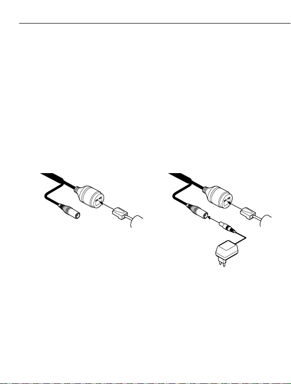
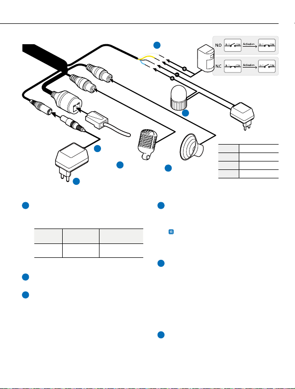
Table of contents
Other Viewpro Security Camera manuals


