ViewSonic NextVision HD-12 User manual


1
Copyright© ViewSonic Corporation, 2004. All rights reserved.
ViewSonic, the three birds logo and OnView are registered trademarks of ViewSonic Corporation.
Disclaimer: ViewSonic Corporation shall not be liable for technical or editorial errors or omissions contained
herein; nor for incidental or consequential damages resulting from furnishing this material, or the performance or
use of this material, or the performance or use of this product.
In this interest of continuing product improvement, ViewSonic Corporation reserves the right to change product
specifications without notice. Information in this document may change without notice.
No part of this document may be copied, reproduced, or transmitted by any means, for any purpose without prior
written permission from ViewSonic Corporation.
Electronic Warranty Registration
To meet your future needs, and to receive any additional product information as it becomes available, please register
your warranty on the Internet at http://www.viewsonic.com
FOR YOUR RECORDS
This serial number of this product is on the back of the HDTV receiver. Write the serial number
in the space below and keep this guide as a permanent record of your purchase to aid in
identification in the event of theft or loss.
Model Name:ViewSonic NEXTVISION HD12
Model Number: VS10321-1M
Serial Number:
Purchase Date:

2
Safety First
Please review the following safety precautions. If this is first time to use a terrestrial TV receiver, then read this
manual before installing or using the terrestrial TV receiver. If the receiver is not functioning properly, please
contact ViewSonic customer support.
The lightening symbol in a triangle is used to alert you to the presence of dangerous voltage inside the receiver that
may be sufficient to constitute a risk of electric shock to anyone opening the case. It is also used to indicate improper
installation or handling of the receiver that could damage the electrical system in the receiver or in other equipment
attached to the receiver.
The exclamation point in a triangle is used to alert you to important operating and maintenance instructions.
Failure to follow these instructions could result in injury to you or damage to the receiver.
Be careful with electricity:
Power outlet: To prevent electric shock be sure the electrical plug used on the receiver’s power cord matches
the electrical outlet used to supply power to the receiver. Connect the power cord only to a power
source that operates at 90~260 Volts AC, 50/60 Hz.
Power plug: If a three-prong power plug is provided with the receiver, be sure it is used with a properly
grounded three-wire power socket.
Power cord: Be sure the power cord is routed so that it will not be stepped on or pinched by heavy items.
Power overloading: Avoid overloading electrical outlets or extension cords, which otherwise could result in
electric shock or fire.
Lightening: For protection from lightening, or when the receiver is left unattended for a long period,
disconnect it from the power source.
Protect other equipment: Unplug the receiver before connecting any other equipment, especially the TV
antenna Connect all equipment to the receiver before plugging any power cords to
the power source.
Power line: Be sure your TV antenna is not located near overhead power lines, or where it might fall into
any power lines. Also be careful to avoid touching any such power lines when installing the
TV antenna.
Antenna Grounding: Be sure that antenna is grounded to provide protection from Lightening and build-up
of static electricity.
Antenna Installation Instruction:
1. Outdoor Antenna Grounding:
If an outside antenna or cable system is concerned to the product be sure the antenna or
cable system is grounded so as to provide some protection against voltage surges and
built-up static charges, Article 810 of the National Electrical Code, ANSI/NFPA 70,
provides information with regard to proper grounding of the mast and supporting
WARNING!
RISK OF ELECTRICAL SHOCK
DO NOT OPEN
WARNING:
TO REDUCE THE RISK OF ELECTRICALSHOCK
DO NOT REMOVE THE COVER
NO USER-SERVICEABLE PARTSARE INSIDE
REFER SERVICINGTO QUALIFIED PERSONNEL

3
structure, grounding of the lead-in wire to an antenna discharge unit, connection to
grounding electrodes, and requirements for the grounding electrodes.
2. Lightning:
For added protection for this product during a lightning storm, or when it is left
unattended and unused for long periods of time, unplug it from the wall outlet and
disconnect the antenna or cable system. This will prevent damage to the product due to
lightning and power-line surges.
3. Power Lines:
An outside antenna system should not be located in the vicinity of overhead power lines
or other electronic light or power circuits, or where it can fall into such power lines or
circuits. When installing an outside antenna system, extreme care should be taken to
keep from touching such power lines or circuits as contract with them might be fatal.
Also follow these precautions:
Ventilation: Do not block the ventilation slots on the receiver, or place any heavy object on top of it.
Blocking the air flow could damage the receiver. Arrange components so that air can flow freely around the
receiver. Ensure that there is adequate ventilation if the receiver is placed in a stand. Put the receiver in a
properly ventilated area, away from direct sunlight or any source of heat.
Overheating: Avoid stacking the receiver on top of a hot component such as a power amplifier.
Risk of Fire: Do not place the receiver on top of any easily combustible material, such as carpet or fabric.
Proper Connections: Be sure all equipment cables are connected to the receiver as described in this manual.
Object Entry: To avoid electric shock, never stick anything in the slots on the case or remove the cover.
Water Exposure: To reduce the risk of fire or electric shock, do not expose the receiver to rain or moisture.
EMI (Electro Magnetic Interference) tested

4
Table Of Content
Safety First.................................................................................................................................. 2
Table Of Content.......................................................................................................................... 4
Introduction to NextVision HD12 ................................................................................................... 6
Package Contents ........................................................................................................................ 6
Frond Panel Buttons and LEDs ...................................................................................................... 7
Rear Panel Jacks.......................................................................................................................... 8
HD12 Physical Installation............................................................................................................. 9
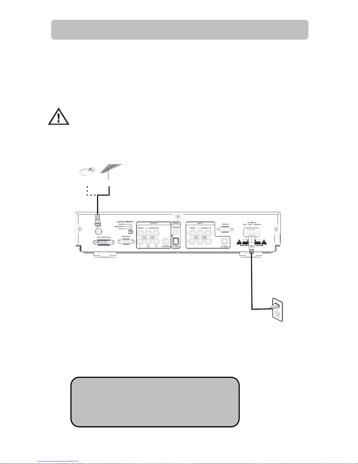
Connecting Antennas ................................................................................................................... 8
TV Connection - Analog TV ........................................................................................................... 9
TV Connection - HDTV TV or Monitor (YPbPr)............................................................................... 11
TV Connection - HDTV TV or Monitor (RGB) ................................................................................. 12
TV Connection - HDTV TV or Monitor (DVI with HDCP).................................................................. 13
Video Source Connection ............................................................................................................ 14
Viewing the Remote Control........................................................................................................ 15
Battery Installation..................................................................................................................... 15
MENU Map ................................................................................................................................ 16
Hotkey Map............................................................................................................................... 18
Setting Up The ZAT-500HD RECEIVER ......................................................................................... 19
Channel .................................................................................................................................... 19
Auto Scan ................................................................................................................................. 20
Memorize Channel Manually........................................................................................................ 21
Edit Channel.............................................................................................................................. 22
Caption (Closed-Caption Options)................................................................................................ 23
Setup........................................................................................................................................ 24
Format (Screen Format Setup) .................................................................................................... 24
Aspect Ratio .............................................................................................................................. 25
Sound (Digital Audio Output Setting) ........................................................................................... 26
Opacity (Changing Transparency of On-Screen-Display)................................................................. 26
I-Plate (Changing Display time of the information-Plate)................................................................ 26
Time Zone................................................................................................................................. 27
About (Receiver Information)...................................................................................................... 27
Lock ......................................................................................................................................... 28
Rating (Lock Programs Using the USTV(FCC) or MPAA) ............................................................... 28
Important information About "Parental Rating" ............................................................................. 29
Change Password....................................................................................................................... 30
Reset Receiver's Data To Default ................................................................................................. 30
Forget the Password? ................................................................................................................. 30
INFO (Information-Plate)............................................................................................................ 31

5
Audio(Select a Multitack Language when Receiving DTV Program) ................................................. 31
MTS (Set Audio when Receiving Analog TV Program) .................................................................... 32
EPG (Electric Program Guide)...................................................................................................... 32
Channel Guide ........................................................................................................................... 32
INPUT (External Video/Audio Input) .......................................................................................... 33
PIP (To watch two channels at the same time) ........................................................................... 33
PIP Position (To Move Small Picture Position in Picture In Picture) .................................................. 34
PIP SWAP (To Swap Big and Small Picture In PIP)......................................................................... 34
POP (Picture On Picture)............................................................................................................. 35
CLOSED CAPTION...................................................................................................................... 35
FAVORITE CHANNEL LIST........................................................................................................... 36
Press Numeric Key to Select Digital Channel ................................................................................. 36
FREEZE the PICTURE ................................................................................................................. 36
APPENDIX 1 DTV Channel Table Information ............................................................................ 38
APPENDIX 2 TROUBLE SHOOTING .......................................................................................... 39
APPENDIX 3 ON SCREEN MESSAGE ......................................................................................... 40
APPENDIX 4 GLOSSARY.......................................................................................................... 41
APPENDIX 5 TECHNICAL SPECIFICATIONS............................................................................... 42

6
Introduction to NextVision HD12
Getting Started
Thank you for choosing ViewSonic! Your new NextVision HD12 HDTV receiver is designed to receive
free-to-air ATSC terrestrial TV channels. The receiver is operated via the remote control as indicated in
the following pages. The receiver also provides a wide variety of options for attaching to your TV and
other home entertainment equipment by connector of DVI, RGB, Component Video Y/Pb/Pr, Composite
Video (RCA), S-Video, Audio L/R (RCA) and Coaxial SPDIF.
If your service provider or system installer has already set up the TV antenna and connected it to the
receiver, then you may want to skip this section. However, if you are setting up the system by yourself,
please read this section through "Connecting To Audio Video Devices" on page 9 and 10, and be sure
you follow all the precautions listed under “Safety First”.
Note: Installation procedures for TV antenna and related equipments are not covered in this manual
Package Contents
Unpack the product and verify that all of the following items are included. Remember to keep the
packaging in case you need to return the receiver for service. Examine all the items to ensure that
nothing has been damaged during shipment. If any of the items is damaged, please contact ViewSonic
before continuing with installation.
NextVision HD12 HDTV receiver
Remote Control (with 2 AAA batteries)
Audio/Video cable with RCA jacks
Component video cable (Y/Pb/Pr)
Power cable
This user’s manual

7
Frond Panel Buttons and LEDs
POWER
MENU
SELECT
EXIT
Power
Press to turn the Receiver ON or OFF.
Right arrow button
Move the cursor or field in the right direction with in OSD screen. It also can increase volume level if no
cursor control is required.
Left arrow button
Move the cursor or field in the left direction with in OSD screen. It also can lower volume level if no cursor
control is required.
Up arrow button
Move the cursor or field in the upward direction with in OSD screen. It also can select one channel higher
than the present channel if no cursor control is required.
Down arrow button
Move the cursor or field in the downward direction. It also can select one channel lower if no cursor control is
required
Menu/Select
Display the OSD menu on the screen and select highlighted options or values in the menus.
Exit
Go to the previous OSD menu or exit the main OSD menu.
LED Display
The display is a 4-digit 7 segments LED display.

8
Rear Panel Jacks
OUTPUT
AUDIO
RF IN
RGB OUT
PbY
OUTPUT SWITCH
RGB DVI (V)
Y Pb Pr
/
DVI (C)
VIDEO L
100 ~ 240V 50/60 Hz
AUDIO
OPTICALS-VIDEOPr
2
1
RCOAXIAL
S/PDIF
VIDEO L
INPUT
S-VIDEO
R
RS-232
AC INPUT
DV I H DCP OUT
RF In
Connect it with UHF/VHF antenna for terrestrial Digital-ATSC/Analog-NTSC TV signal input
Video with Audio L/R In 1
Is used to connect the first Composite Video input source.
Video with Audio L/R In 2
Is used to connect with Composite Video input source two.
S-Video In with Audio L/R In 1
For connecting Video Source device with S-Video output, its audio input will share with the Video In 1.
CoaxialS/PDIFOut
Connect it through the coaxial cable with the Dolby Digital compatible A/V Receiver (decoder/amplifier) for
Dolby Digital 5.1 channel audio.
Optical S/PDIF Out
Connect it through the fiber cable with the Dolby Digital compatible A/V Receiver (decoder/amplifier) for
Dolby Digital 5.1 channel audio.
S-VideoOutput
Connect it with TV monitor’s S-Video input
Audio L/R Out
Connect them with TV monitor’s Audio L / R input connector RCA jacks.
YPbPrOut
Connect it with HD or Wide-screen TV monitor’s YPbPr video inputs, and then the Output Switch shall
switch to “YPbPr” section.
Composite Video Out
Connect them with TV monitor’s Video input RCA jacks
Output Switch
1. YPbPr: Switch when the YPbPr output is used to connect HDTV or Monitor.
2. RGB/DVI (V): RBG or DVI output is used when connecting with the “VESA Timing” Monitor or TV.
3. DVI (C): RBG or DVI output is used when connecting with the “Component Timing” Monitor or TV.
RGB Out
Connect it with TV monitor’s RGB input connector, while the Output Switch shall be switched to “RGB/DVI
(V)” or “DVI (C) ”position.
DVI with HDCP Out
Connect them with TV monitor’s DVI input connector, while the Output Switch shall be switched to
“RGB/DVI (V)” or “DVI (C) ”position.
Note: The Receiver DVI with HDCP output is the one that is compliant with EIA-861 and HDCP
specification. Check your TV or monitor’s user manual to find out if the TV or monitor’s DVI is compliant
with these specifications, or you cannot see any picture on your TV or monitor.
PowerConnector
AC power input, 100-240V, 50-60Hz.
RS-232
For service only.

9
HD12 Physical Installation
There are many ways to connect the HD12 Receiver to your home entertainment system, depending on
the equipment and connection types you have. However, for the best video/audio quality, use the higher
quality Y/Pr/Pr or DVI connections if available. And always remember to disconnect the receiver from the
power source prior to connecting or after disconnecting the cable to the UHF/VHF antenna.
Before Connecting to other devices
When the receiver is connected to the antenna attached with a signal amplifier which requires
power supply, be sure the amplifier doesn't have power leakage before connecting the coaxial
cable to the receiver.
Connecting Antennas
1. Connect Antenna to the Receiver RF Input by using a coaxial RF cable.
2. You may connect Cable NTSC signal to the receiver by using a coaxial RF cable.
Note: except the terrestrial ATSC signal, the Receiver
also could receive the traditional NTSC signal, please note
that it could not recognize the digital cable QAM signal to
decode.
Cable Antenna
or

10
TV Connection – Analog TV
2
RF IN
S-VIDEO
OPTICAL
TV
COAXIAL
A
udio
Receiver
Cable Antenna
or
1. Connect the Antenna or Cable to the Receiver RF Input by using a coaxial RF cable.
2. Connect the “VIDEO OUTPUT” and “AUDIO OUTPUT” to the “A/V IN” jack on your TV
by using RCA-type cables. You also could use the S-VIDEO instead of the VIDEO. Uses
the S-VIDEO cable to connect the Receiver “S-VIDEO OUT” to your TV “S-VIDEO IN”.
3. If you have the “Home Theater” audio system, connect the “Coaxial S/PDIF” or
“Optical S/PDIF” to your “Dolby Digital compatible A/V Receiver” by using the fiber or
RCA-type coaxial cable.

11
TV Connection – HDTV TV or Monitor (YPbPr)
RF IN
DVI OUT RGB OUT
OUTPUT SWITCH
RL
VIDEO AUDIO
OUTPUT
COAXIAL
YPbPr
S-VIDEO OPTICAL
A
UDIO
VIDEO L
INPUT
R
1
2
S-VIDEO
RS-232
S/PDIF 100 ~ 240V 50/60 Hz
AC INPUT
Y Pb Pr
DVI
(
C
)
RGB / DVI (V)
2
RF IN
S-VIDEO
OPTICAL
COAXIAL
TV
A
udio
Receiver
1
Cable Antenna
or
OUTPUT SWITCH
Y Pb Pr
DVI (C)
RGB /DVI (V)
1. Connect the Antenna or Cable to the Receiver RF Input by using a coaxial RF cable.
2. Connect the “YPbPr OUTPUT” and “AUDIO OUTPUT” to the “YPbPr IN” and “AUDIO IN”
jack on your TV by using YPbPr and Audio L/R RCA-type cables.
3. If you have the “Home Theater” audio system, connect the “Coaxial S/PDIF” or
“Optical S/PDIF” to your “Dolby Digital compatible A/V Receiver” by using the fiber or
RCA-type coaxial cable.
Note: when you are using the YPbPr connection, the
“
OUTPUT SWITCH” must be set toward the “YPbPr
”
position.

12
TV Connection – HDTV TV or Monitor (RGB)
OPTICAL
COAXIAL
TV
A
udio
Receiver
Cable Antenna
or
OUTPUT SWITCH
Y Pb Pr
DVI (C)
RGB / DVI (V)
1. Connect the Antenna or Cable to the Receiver RF Input by using a coaxial RF cable.
2. Connect the “RGB OUT” and “AUDIO OUTPUT” to the “RGB IN” and “AUDIO IN” jack
on your TV by using RGB and Audio L/R RCA-type cables.
3. Connect the “Coaxial S/PDIF” or “Optical S/PDIF” to the “Dolby Digital compatible A/V
Receiver” by using the fiber or RCA-type coaxial cable if you have the “Home Theater”
audio system.
Note: when you are using the RGB connecting, the “ OUTPUT SWITCH
”
must be set toward the “RGB/DVI (V)” or “DVI (C)” position. The HDTV T
V
or Monitor RGB signal reception timing setting depends on the
manufacture’s setup. However, you could try both of switch position till you
could see the Receiver’s picture on TV screen.

13
TV Connection – HDTV TV or Monitor (DVI with HDCP)
OPTICAL
COAXIAL
TV
A
udio
Receiver
Cable Antenna
or
OUTPUT SWITCH
Y Pb Pr
DVI (C)
RGB / DVI (V)
1. Connect the Antenna or Cable to the Receiver RF Input by using a coaxial RF cable.
2. Connect the “DVI OUT” and “AUDIO OUTPUT” to the “DVI IN” and “AUDIO IN” jack on
your TV by using DVI and Audio L/R RCA-type cables.
3. Connect the “Coaxial S/PDIF” or “Optical S/PDIF” to the “Dolby Digital compatible A/V
Receiver” by using the fiber cable or RCA-type coaxial if you have the “Home Theater”
audio system.
Note: when you are using the DVI connecting, the “ OUTPUT SWITCH” must be
set toward the “DVI (C)” position. The Receiver DVI with HDCP output is the
one that is compliant with EIA-861 and HDCP specification. Check your TV or
monitor’s user manual to find out if the TV or monitor’s DVI is compliant with
these specifications, or you cannot see any picture on your TV or monitor.

14
Video Source Connection
1. You could connect Video source like DVD, VCR, LD or Cable/Satellite Receiver by using
the Composite Video or S-Video cable.
2. Connect the “AUDIO OUT” jack on the video source device to the receiver’s “Audio IN”
by using Audio L/R RCA-type cables.
Note: when you are using the S-VIDEO for connecting
the Video-Source-Device to the Receiver, please note that
the Receiver’s S-VIDEO audio input is set on the first pair
of Audio L/R INPUT RCA jack.

15
Viewing the Remote Control
Battery Installation
Use two AAA batteries (supplied)
Remove battery cover by pushing the tab while lifting the cover up. Install batteries matching (+) and (-)
polarity signs. Replace the battery cover.
Note: incorrect installation can cause battery leakage and corrosion that will damage the Remote Control.
Precautions
Replace batteries in pairs. Do not mix battery types (zinc carbon with alkaline). Do not recharge, heat,
and short circuit, disassemble, or burn batteries.
1
2
3
4
56
7
89
0
Button Description
Power Press to turn ON and OFF the device
Numeric Buttons Press to enter channel number or password
MUTE Press to turn off the audio output
CC/CS Press to call up the Closed Caption (CC) and Caption
Service (CS) list. You can select one the desired
Closed Caption.
INFO
Press to displays I-Plate, providin
g
information about
the current channel, press twice to see the pro
g
ram
extend information
AUDIO Press to select multi-lingual Audio soundtracks
MENU Press to activate or close the On-Screen Display
EXIT Press to back to the previous menu page
EPG Press to display the Electric Program Guide
FAV Press to displays the “ALL”, “Digital”, “Analog” and
“Favorite” program list.
Direction buttons Press to move hi
g
hli
g
hted selection throu
g
h menu or
submenus
Enter Press highlight menu or submenu item
CH+/CH-Press to scroll channel up and down.
VOL+/VOL-Press to increase or decrease audio volume
V. FORMAT
Press to change the picture resolution between 1920
X 1080i; 1280 x 720p; 720 x 480p; and 720 x 480i video
format for YPbPr, RGB or DVI output.
A. RATIO Press to ad
j
usts the aspects ratio between 16:9 and
4:3 modes.
FREEZE Press to pause the Picture in Picture
INPUT Press to change the auxiliary input from Tuner, Video
1, Video 2 or S-Video.
POP (Red) Press to display the Picture on Picture
PIP (Green) Press to display or delete PIP frame
PIP.POS (Yellow) Press to change PIP Frame location in PIP mode
PIP.SWAP (Blue) Press to swap Main picture with PIP frame in PIP
mode

16
MENU Map
OSD Menu Tree
Channel Lock Setup
Edit Favorite Lists Setup
Auto Scan (ATSC & NTSC) Scan Ch2~69
Off Air (ATSC&NTSC) Enter Ch Scan
Cable STD Enter Ch Scan
Cable IRC Enter Ch Scan
Channel Enter
Password
Manual Scan
Cable HRC Enter Ch Scan
Default
Small
Middle
Font Size
Large
Default
Style0
Style1
Style3
Style4
Style5
Style6
Font Style
Style7
Default
Red
Black
Background
Green
Yellow
Pink
Light Blue
Font Color
Foreground
Blue
Default
Background Solid Full
Translucent Fill
Caption
Font Opacity
Foreground Transparent Fill
480i(720x480) 4:3 (Letterbox)
480p(720x480) 4:3(Zoom)
720p(1280x720) 4:3(Full)
4/3(ratio)
1080i(1920x1280)
480i(720x480) 16:9 (Pillar box)
480p(720x480) 16:9(Zoom)
720p(1280x720) 16:9(Full)
Format
16/9(ratio)
1080i(1920x1280)
PCM
Sound Dolby Digital
Opacity 0%~100%
adjustment
I-Plate Display Time Seconds Setting 2.4.6 sec / off
Time Format 12 or 24
Time Zone Time
Adjustment 30min/per
Setup
About HW & SW
version
N/A
G
PG
Lock Enter
Password
Rating MPAA
PG-13

17
R
NC-17
X
None
TV-Y
TV-Y7 FV
TV-G V
V
S
L
TV-PG
D
V
S
L
TV-14
D
V
S
USTV
TV-MA
L
Password Enter Password New Password Confirm New
Password
Reset Box Confirm Reset Reset

18
Hotkey Map
Item Name Hot Key Function
On
1 POWER
OFF
OFF(default)
CC1
CC2
CC3
2 CC/CS (Closed Caption)
CC4
3 MUTE Press to turn-off /on audio output
4 #0~#9 Numerical keypad (Channel Number)
Language 1(ATSC)
Language 2(ATSC)
5 AUDIO
Language 3(ATSC)
6 INFO.
Displays I-Plate providing information about the
current channel
7 FAV.
Display the favorite channel list.
(MAIN+ATSC+NTSC+FAV. )
8 EPG
Press to display the Program Guide window, press
again could show the Channel Guide window
9 MENU Activates or turn off the On Screen Menu
10 CH ▲CH▼Control the channel up/down
11 VOL +VOL - Control the volume increase/decrease
Format:480i
Format:480P
Format:720P
12 V. Format
Format:1080i
4:3 (LetterBox)
4:3 (Pan&Scan)
4:3 (Crop)
16:9 (PillarBox)
16:9 (Pan&Scan)
13 A.RATIO
16:9 (Crop)
14 FREEZE Freezes the picture on the main screen
PIP-OFF
C-Video 1
C-Video 2
S-Video
DigitalTV1
15 PIP(Green)
DigitalTV2
Up
Down
Left
16 PIP.POS
Right
17 PIP.SWAP
Swap between Main Video window and PIP1 Video
window
Mono
Stereo
18 MTS (Audio Key in
receiving analog TV) Sap
19 POP(Red)
Displaying a current selected channel program
surrounding by 8 sub-pictures.
20 Timing Switch (HW) Component/VESA Timing on RGB & DVI output
TV mode
C1-Video
C2-Video
21 INPUT
S-Video

19
Setting Up The HD12 RECEIVER
1. Make sure the physical connection is properly connected.
2. Switch on the TV.
3. Select the appropriate external video input on your TV by using the TV remote control.
4. Select the appropriate video output on the Receiver by using the Receiver video output switch.
5. Make sure the receiver is already in power-on mode. If it is in off mode (i.e. front panel shows ----),
switch on the receiver by pressing the “POWER” button on the front panel of the receiver or on the
remote control.
6. If the box is moved to a different location. You should reset the box to factory default (Page 31) and
do the channel scanning all over again.
Press the “MENU” button to see the Menu banner.
Channel
Before you can use any of the channel buttons (CH ▲▼, FAV.), the available channels must first be
scanned and memorized.
Initial Screen –
●The first time when the receiver is powered on,
you will see a message block of “Press (Menu)
key and then select Channel to run
Auto/Manual Scan”. Press the MENU button to
display the MENU banner.
●Use the arrow keys ◄or ►to move highlight
through the menu banner, the highlight icon will
lead to show those second layer function items.
●Press “EXIT” button will return to the previous
menu or press “MENU” key to directly leave the
menu.
Other manuals for NextVision HD-12
1
This manual suits for next models
1
Table of contents
Other ViewSonic Media Converter manuals
Popular Media Converter manuals by other brands

parkell
parkell TurboSENSOR Instructions for use

StarTech.com
StarTech.com VCSVIDVGA Instruction guide

SICK
SICK AFS60 S01 operating instructions

Wyco
Wyco SELECT-Cycle SC1430 user manual

GREAT PLAINS
GREAT PLAINS Verti-Till VT5300 Assembly instructions

SEW-Eurodrive
SEW-Eurodrive DR.71-225 operating instructions

MRC
MRC 0001636 quick start guide

Texas Instruments
Texas Instruments LM5157 Q1 Series manual

PROception
PROception PRODMHD11 Installation & configuration manual

ADF Web
ADF Web HD67C77-B2 user manual

novotechnik
novotechnik 4800-R Instructions for use

IMC Networks
IMC Networks IE-MiniFiberLinX-II Operation manual