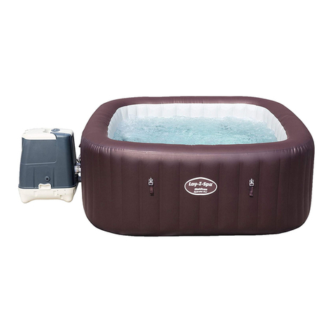
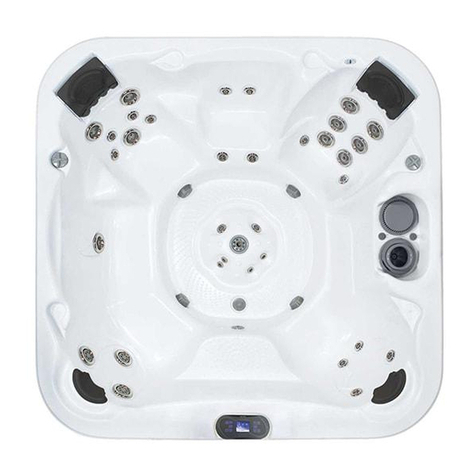
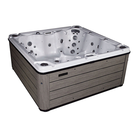
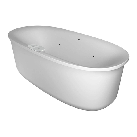
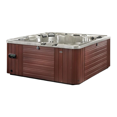
Viking spas Viking 1P 120v User manual

2021 Owner’s Manual

TAB E OF CONTENTS
• Important Safety Instructions 2
Personal Safety Precautions 4
Installation an Set-Up Instructions 5
Electrical Requirements 5
Wiring Installation (220v) 6
GFCI Wiring Installation (220v) 7
Electrical Specifications 8
• Spa Startup Directions 8
• Plug and Play Cord ocation 9
• Operation Instructions
Topsi e Control Instructions 10
Waterfall A justability 11
LED Lighting Feature 11
Spa Jets an Air Controls 12
• Filling Directions
Stereo Operation 14
Vibrosonic Jet Operation 14
Fill the Spa With Water 14
Skimmer Si e Filter 15
A Start-Up Chemicals 15
• Maintenance 16
Spa Draining 16
Spa Surface Care 17
Long-Term Storage 17
Pillow Maintenance 17
Filter Cleaning 18
Spa Cabinet & Cover Maintenance 20
• Ozonator 20
• Gallon Specifications 20
• Spa Situations & Solutions 21
• Trouble Shooting 22
1

IMPORTANT SAFETY INSTRUCTIONS
When installing an using this electrical equipment, basic safety precau-
tions shoul always be followe , inclu ing the following:
READ AND FO OW
A INSTRUCTIONS
1. WARNING: To re uce the risk of injury, o not permit
chil ren to use this pro uct unless they are closely supervise
at all times. Keep spa cover locke when not in use.
2. A wire connector is provi e on this unit to connect a minimum
No. 8 AWG (8.4mm2) soli copper con uctor between this
unit an any metal equipment, metal water pipe or con uit
within 5 feet (1.5m) of the unit.
3. DANGER: Risk of Injury. The suction fittings in this spa are
size to match the specific water flow create by the pump.
Shoul the nee arise to replace the suction fittings or the
pump, be sure that the flow rates are compatible. Never
operate the spa if the suction fittings are broken or missing.
Never replace a suction fitting with one rate less than the flow
rate marke on the original fitting.
4. DANGER: Risk of Acci ental Drowning. Extreme Caution
must be exercise to prevent unauthorize access by chil ren.
To avoi acci ents, insure that chil ren cannot use this spa
unless they are supervise at all times.
5. DANGER: Risk of Electric Shock. Install at least 5 feet (1.5m)
from all metal surfaces. As an alternative, a spa may be
installe within 5 feet of metal surfaces if each metal surface is
permanently connecte by a minimum No. 8 AWG (8.4mm2)
soli copper con uctor to the wire connector on the terminal
box that is provi e for this purpose.
2

6. DANGER: Risk of Electric Shock. Do not permit any
electrical appliance, such as a light, telephone, ra io or
television within 5 feet (1.5m) of a spa.
7. WARNING: To Re uce the Risk of Injury:
a) Before using your spa you shoul check the water
temperature with a thermometer that is known to be
accurate. The water temperature in a spa shoul never
excee 104°F (40°C). A water temperature of 104°F is
consi ere safe for a healthy a ult. Lower water
temperatures are recommen e for young chil ren an
when spa use excee s 10 minutes.
b) Since excessive water temperatures have a high potential for
causing fetal injury uring the early months of pregnancy,
pregnant or possibly pregnant women shoul limit spa
water temperature to 100°F (38°C).
c) The use of alcohol, rugs, or me ication before or uring
spa use may lea to unconsciousness with the possibility of
rowning.
) Persons suffering from obesity or with a me ical history of
heart isease, low or high bloo pressure, circulatory
system problems or iabetes shoul consult a physician
before using a spa.
e) Persons using me ication shoul consult a physician before
using a spa since some me ication may in uce rowsiness
while other me ications may affect heart rate, bloo
pressure an circulation.
8. The causes, symptoms an affects of hyperthermia may be
escribe as follows:
Hyperthermia occurs when the internal temperature of the bo y
reaches a level several egrees above the normal temperature
of 98.6°F. The symptoms of hyperthermia inclu e an increase
in the internal temperature of the bo y, izziness, lethargy,
rowsiness an fainting.
The effects of hyperthermia inclu e:
• Failure to feel heat
• Failure to recognize the nee to exit the spa
• Unawareness of impen ing hazar s
3
• Fetal injury in pregnant women
• Physical inability to exit the spa or hot tub
• Unconsciousness resulting in the potential of rowning
9. WARNING: The use of alcohol, rugs or me ication can
greatly increase the risk of fatal hyperthermia. If you suspect
hyperthermia, imme iately get me ical help, lay the victim on
their back with the hea slightly elevate for easier breathing,
cover the bo y with a blanket an apply ice packs to the
hea .
10. Never touch or come in contact with any electrical accessory
when in your spa or when your bo y is wet.
11. Prior to performing any service to the spa pack, turn off ALL
power to the system at the main power source breaker.
NOTE: A READI Y ACCESSIB E DISCONNECTING MEANS
SHA BE PROVIDED DURING INSTA ATION.
SAVE THESE INSTRUCTIONS
PERSONA SAFETY PRECAUTIONS
1. Please use the spa when others are present.
2. Chil ren shoul have spa access only with the permission an
supervision of an a ult.
3. To re uce the risk of chil rowning, keep the spa filter clean
an unclogge . Do not mo ify the suction or filtration
systems.
4. Exercise caution when entering or leaving the spa. When
moving or changing positions, be sure of your footing before
applying your full weight as water refraction can be
mislea ing.
5. Do not stay in the spa for exten e perio s of time. Set a
reasonable time limit after which you leave the spa, cool
own, take a shower, relax an then return for another stay in
the spa.
4

INSTA ATION AND SET-UP INSTRUCTIONS
SURFACE AND PAD REQUIREMENTS
• Your new portable spa must be place on a uniformly firm,
flat an level surface. A concrete pa 4 inches thick is best.
• In or er to prevent floo ing of the electrical equipment, the
pa must be such that water will rain away from the spa.
• If your spa is locate near sprinklers, a just or cap them so
as not to hit the si ing of the spa.
NOTE: Do not put your spa on any soft surface such as san , grass,
crushe rock or irt. Any settling surface will put an uneven pressure an
tension to the spa structure an may voi the warranty.
BA CONIES AND DECK REQUIREMENTS
• Decking must be constructe to support 85 poun s per sq. ft.
• Balconies must be constructe to meet current state an
local co es.
• Gates must be self-closing an self-latching.
E ECTRICA REQUIREMENTS
NOTE: Name ba ge on rub rail in icates equipment location
15 amp GFCI Rating
Viking 1P 120v, Viking 2P 120v, Aurora P 120v, Aurora P+ 120v,
Royale P 120v, Royale P+ 120v, Regal P 120v, Regal P+ 120v
50 amp GFCI Rating
Viking 3, Aurora 3, Royale, Regal, Royale ETS, Regal ETS, Legacy 1 &
Legen 1
60 amp GFCI Rating
Legacy 2, Legen 2, Heritage 1 & 2, Tra ition 1 & 2,
• Your 110-volt or 220-volt spa pack is esigne to be
“PERMANENTLY CONNECTED”.
• It is the customer’s responsibility to acquire necessary
permits and to arrange for installation and hook up of
the electrical power. 5

220-VO T
\
6
*Green groun connection locate on left si e of control panel.
WHITE
BLACK
RED
GREEN*

GFCI WIRING INSTA ATION (220V)
7

E ECTRICA SPECIFICATIONS
GENERA
NOTICE: All spa electrical wiring must be performed by
a qualified, licensed electrician in order to meet NEC
(National Electrical Code) state and local codes.
1. The lines carrying power to the spa must be e icate to the
spa an shoul not be share with any other appliance(s).
2. All electrical wiring lines must originate from the electrical
panel an terminate, har wire , into the electrical wiring
compartment. The use of extension cor s or improper plug
type termination is expressly prohibite an voi s the warranty.
3. Do not use aluminum wiring. Use only copper conductive
wiring.
4. Wire gauge must be in accordance with NEC
requirements for the istance from current source to spa an
the current rating as state on the ID label that is attache to
the equipment control enclosure.
5. All wiring installe in con uit must be approve for usage
by state an local co es. The con uit must terminate at the
electrical access compartment either from the bottom of the
spa or through a hole in the si e panel of the spa.
SPA STARTUP DIRECTIONS
All Viking Spas require a soli , flat surface.* This is to ensure that the
spa cabinet is not expose to a pressure stress con ition that may result
in cabinet amage an shell cracking. A concrete pad is the best
example of a solid, flat surface, however, wood decking
is suitable, provided it can withstand 85# per sq. ft. with-
out deflection.
* FAI URE TO PROVIDE A PROPER, SO ID, F AT SURFACE
MAY DAMAGE YOUR SPA AND VOID YOUR WARRANTY.
Please check with a license contractor an local co es prior to any
construction.
8

Plug & Play Cord ocation
For square plug an play spas, the GFCI cor can be accesse
through the notche corner knockout as shown
to the right. You may have to remove the equip-
ment access panel an route the cor through
the opening.
For the roun Viking 1P or 2P spas, you will
nee to remove the panel with the cor cutout in
the lower left han section of the panel to
access the GFCI cor . Attach the panel back
onto the spa with the cor route through the
notch section of the panel.
POWER CORD ACCESS OCATION
Viking Spas has provi e three access points
locate in the bottom corner to assist in running
the electrical con uit to the power system.
Simply remove the plug to access the opening.
9
Receptacle where cord is
located on square plug
and play spas

TOPSIDE CONTRO
OPERATION INSTRUCTIONS
It is very important to make sure that the spa is fille
at least 3/4 way up the skimmer opening. Make sure the gate
valves are in the open or up position.
WARNING: Do not run spa with gate valves close or run pump
with no water circulating in spa for long perio s. Damage coul occur
to the spa equipment.
Warning! / Shock Hazard! / No User Serviceable Parts.
Do not attempt service of this control system. Contact
your dealer or service organization for assistance.
Follow all owner’s manual power connection instruc-
tions. Installation must be performed by a licensed elec-
trician and all grounding connections must be properly
installed.
10
Use the Accompanying QR code for instructions that best
matches the control panel on your spa
OPTIONA Touchscreen
Controller
Installe when purchase
on spas with BP Power Systems
USE QR on left or go to:
http://www.vikingspas.com/ftp/spatouch_usergi e.p f
Controller
Installed on
Viking 1, Viking 2, Aurora P, Aurora P+,
Royale P, Royale P+, Regal P, Regal P+
USE QR on left or go to:
http://www.vikingspas.com/ftp/tp500usergui e.p f
Controller
Installed on
All other spas
USE QR on left or go to:
http://www.vikingspas.com/ftp/240viking_usergi e.p f

WATERFA ADJUSTABI ITY
The Aurora P, Aurora P+an the Aurora 3 feature a Waterfall, which
allows the user to regulate the flow of water to the jet by simply turn-
ing the valve for the waterfall from “off” to “on”. (See illustration
below)
ED IGHTING FEATURE
The Aurora P+, Royale P+, Regal P+, Viking 3, Aurora 3, Royale,
Royale ETS, Regal, Regal ETS, Legacy, Legen , Heritage & Tra ition
Series mo els are also equippe with an LED light system. This light-
ing, which encompasses the interior of the spa, is also incorporate
into the light in the foot well of these mo els. The LED Lighting system
consists of a 7 position controller. The first time the light is turne on,
it will begin to isplay all 7 colors available in an automatic rotating
sequence. Each time you sequence the light on/off, all colors will be
isplaye in ivi ually. It may be necessary to wait 1-2 secon s
between cycling the lights on an off in or er to get to the next color
sequence.
11
Regulates Air
into Jets
NOTE: Close air controls
when not in use.

SPA JETS AND AIR CONTRO S
SPA JETS
A justable Spa Jets may be turne off an on by rotating jet faceplate
left or right.
Note: DO NOT TURN ALL SPA JETS OFF AT THE
SAME TIME. THIS MAY CAUSE DAMAGE TO THE
PUMP AND MOTOR.
Note: To remove jet insert, turn jet face counter-clockwise to the shut
off point. Continue turning until the jet unscrews from bo y. To rein-
stall the jet, insert jet into bo y an turn clockwise until the jet stops.
AirX Jet Option
If installe these re jets will be controlle
using the re matching air control picture .
12
Twin A justable Roto
Directional & Roto Poly
Rotational an Directional
Mini
Directional &
Rotational Cluster

TURBO/WHIR POO JET (Viking 2P & 3 only)
VO CANO Jet (Heritage & Tradition only)
The Turbo jet is locate on the filter cavity wall is
the Turbo jet. This jet is a combination valve
an high capacity jet. To turn the Turbo jet on,
simply turn the face counter-clockwise to the first
stop position. To turn the Turbo jet off, turn the
face clockwise to bring the main jets back to full
power.*
The Volcano Jet operates on a valve
locate in the mi le of the lounger. Turn
the valve to activate the jet. Note: this valve
irects one of the pumps an will effect the
flow
this pump use to power other jets in the spa.
* Due to the substantial amount of water pressure when the Turbo Jet is
operating, you must turn the pump to the off or low spee cycle position
before attempting to rotate the jet face.
AIR CONTRO S
Air controls are a juste by rotating the topsi e ial. These controls
serve to regulate the amount of air mixe with water when the whirlpool
or hy rotherapy jets are operating in the high pump mode.
13
All other models (See illus-
tration on page 14)
Viking 1P, 2P & 3 only

STEREO INFORMATION
If your spa is equipe with a bluetooth stereo you will fin the operating
instructions in the warranty package.
VIBROSONIC JET SYSTEM
If your spa is equipe with a Vibrosonic system you will fin the operat-
ing instructions in the warranty package.
FI THE SPA WITH WATER
a. Clear all ebris from your spa.
b. Remove filter element
c. Using a gar en hose, place hose in filter chamber for filling. Do
not fill higher than three quarters of the way up the skimmer opening
. We DO NOT recommend the use of softened water due
to the potential harm of damaging equipment.
e. As water level rises, check insi e equipment compartments for
water leaks. It may be necessary to tighten loose unions an /or
fittings.
f. Make sure T-Han le Gate VALVES at pump an heater are open,
an the valve han le retaining clips are in place. (Fully exten e up
position).
14

SKIMMER SIDE FI TER
All Viking spas have a skimmer si e filter that oes not require “air
blee ing” on initial startup. If an air lock evelops, loosen the union
on return si e of pump. See Diagram (A) below. Let small amount of
water rain from connection while the pump is running. Once the
water begins to flow out of the jets retighten the union. Make sure
Gate Valve is in the “open” position an the black retainer clip is
snappe into place.
Clean spa filters are critical for proper operation. Dirty filters cause
water restriction to the pump, which in turn may cause erratic heating
of the spa. A starving pump will egra e performance, result in irty
or murky water an may cause the heater to malfunction.
ADD START-UP CHEMICA S
Ask your spa retailer to HELP you set up a chemical maintenance program.
The importance of chemical balance in your spa cannot be overem-
phasize .
SANITIZING: Please refer to your ealer supplie sanitizing recom-
men ations for your start up proce ures.
NOTE: If you live in an area where city water is not available, or
your spa water shows signs of calcium content, you will nee to a a
“stain n scale” chemical on initial fill an then once a week, thereafter.
* Staining of shell due to improper use of chemicals
(as recommended by chemical manufacturer) will not be
considered a warranty defect by Viking Spas.
15
(A)

MAINTENANCE
SPA DRAINING
Every 90 ays, epen ing upon water con ition, you may nee to
renew the spa water. To rain your spa, power must be isconnecte
at the circuit breaker. Locate the rain faucet insi e the spa cabinet
(for Viking IP, 2P & 3 mo els) or on the corner near the bottom of the
si e panel next to the equipment (for all other mo els). 1. Twist cap off
an attach a gar en hose to the opening. 2. Turn the outsi e bo y
counter clockwise until it stops. 3. Pull on the rain that the hose is
connecte to until you hear a pop. 4. Drain the spa. 5. Reverse this
proce ure to shut the water off. Note: the rain will not remove all of
the water in the spa. You may have to remove a small amount of
water by han .
DRAIN OCATIONS
Water Gate Valve
Drain for Viking IP, 2P
& Viking 3 Models
Drain for all
other Models
Operation instructions are virtually the same for all of our mo els.
16

SPA SURFACE CARE
Do not use abrasive solvents or cleaners to clean spa
surfaces. Only use the following: emon Juice, Amonia,
Vinegar or Soap and Water.
ONG-TERM STORAGE (90 days or more)
We strongly urge you to contact your dealer to winterize
your spa. If you are not going to use your spa for an exten e perio
of time, rain it as escribe above. You will also have to rain the
pump. Water left in the spa uring long-term storage may cause freeze
amage.*
To rain the pump, remove the rain plug from the face of the pump.
A itional water removal is require to prevent freeze amage to the
spa plumbing assembly. Remove the piping assembly between the
pump an the heater by loosening the union at the pump an the
union at the heater. Once the piping is remove , use a wet/ ry shop
vac to vacuum water from both the pump si e an the heater si e
openings. Once all water is remove from these lines, we also recom-
men that you place the vacuum over each jet an the suction fittings
an vacuum any remaining water that may be trappe in these lines.
You may now reinstall the piping assembly that was remove earlier
an reinstall the pump plug.
NOTE: We also recommen vacuuming each jet opening to ensure
that all of the water is out of the plumbing lines.
*FREEZE DAMAGE TO THE SPA P UMBING IS NOT COV-
ERED UNDER THE WARRANTY.
SPA PI OW MAINTENANCE
• Your spa pillows nee to be washe an rinse perio ically to
remove any chemical resi ue. This shoul help to eliminate pillows
becoming stiff an iscolore . Note: Your spa pillows are not covere
un er your warranty.
• If the spa is not to be use for a perio of time, pillows shoul be
remove . This will exten the life of the pillow.
17

• Always leave the cover open for 15 minutes every 30 ays to prevent
off gas from amaging your spa pillows, cover an other critical compo-
nents. Signs of off gas amage inclu e but are not limite to pillow peel-
ing an bubbling, iscoloration, cover failing prematurely, plastics or jet
inserts failing. Note: These types of failures are not covere un er your
warranty.
FI TER C EANING
(Viking 1P, Viking 2P & Viking 3)
Your filter shoul be replace once a year. When filters are remove
from the spa, make sure that no objects fall into the filter cavity. They can
cause obstruction to water movement. Remove filter cartri ges as shown
in figures below.
The filter must be cleane every month, more often with heavy use, to get
ri of objects an particles that are lo ge in the filter pleats. Using a
gar en hose with a pressurize nozzle, push water from the insi e to the
outsi e of the filter pleats forcing all trappe particles out. If the filter is
too irty to be cleane as escribe above, obtain filter cleaner material
from your Viking Spa Retailer. Soak the filter overnight; then hose it
own.
A. ocate skimmer. B. Pull weir door open.
C. Remove basket. D. Remove the two separate
filters and follow
cleaning instructions above.
18

FI TER C EANING
(A SPAS except Viking 1P, Viking 2P & Viking 3)
Remove filter face cover by pulling straight up an slightly towar the
spa on front plate/face cover. (As shown below.) Remove access bas-
ket an unscrew filter cartri ge(s) from housing. To reinstall weir oor
assembly, oor must be place through throat of skimmer prior to sli -
ing assembly into place. Refer to filter cleaning proce ure for Viking IP,
Viking 2P & Viking 3 on previous page. Note: Spas with this filter uti-
lize 50 sq. ft. cartri ge filters.
FI TER CARTRIDGE REP ACEMENT
For roun spas use Pleatco™ replacement filter: PWW10 (2 filters) OR
Unicel™ replacement filter: C-4310 (2 filters)
For ALL square spas use Pleatco™ replacement filter: PWW50P3 OR
Unicel™ replacement filter: 6CH940
19
A. ocate skimmer. B. Remove front plate.
C. Remove basket & filters. D. Clean per instructions.
This manual suits for next models
18
Table of contents
Other Viking spas Hot Tub manuals