Viking Stage Lighting VK ST8be LED STROBE User manual

1
with quicklock design
VK ST8be LED STROBE
USER MANUAL
Rev 2.02 RGB & White Versions

VK ST8be LED Strobe / Panel Light
The VK ST8be is a new sort of LED Strobe Light with a brand new concept in design
that enables the unit to be used individually or built into larger modules up to a full
LED wall for incredible White Blinding Effects or using the RGB version, a stunning
wall of coloured pattens and Strobe effects.
Using the quicklock system of interconnection and no additional parts the panels can
be assembled vertically or horizontally to form larger grids of strobe wall or blinders,
ie: 9 single units can make a 3x3 unit. When used as a single unit a Trunion arm is
provided for hanging and angling whereas when assembled into a wall the supplied
half coupler brackets are used to mount the top unit and the Trunion arms are removed
to form a neat solid display effect with no gaps
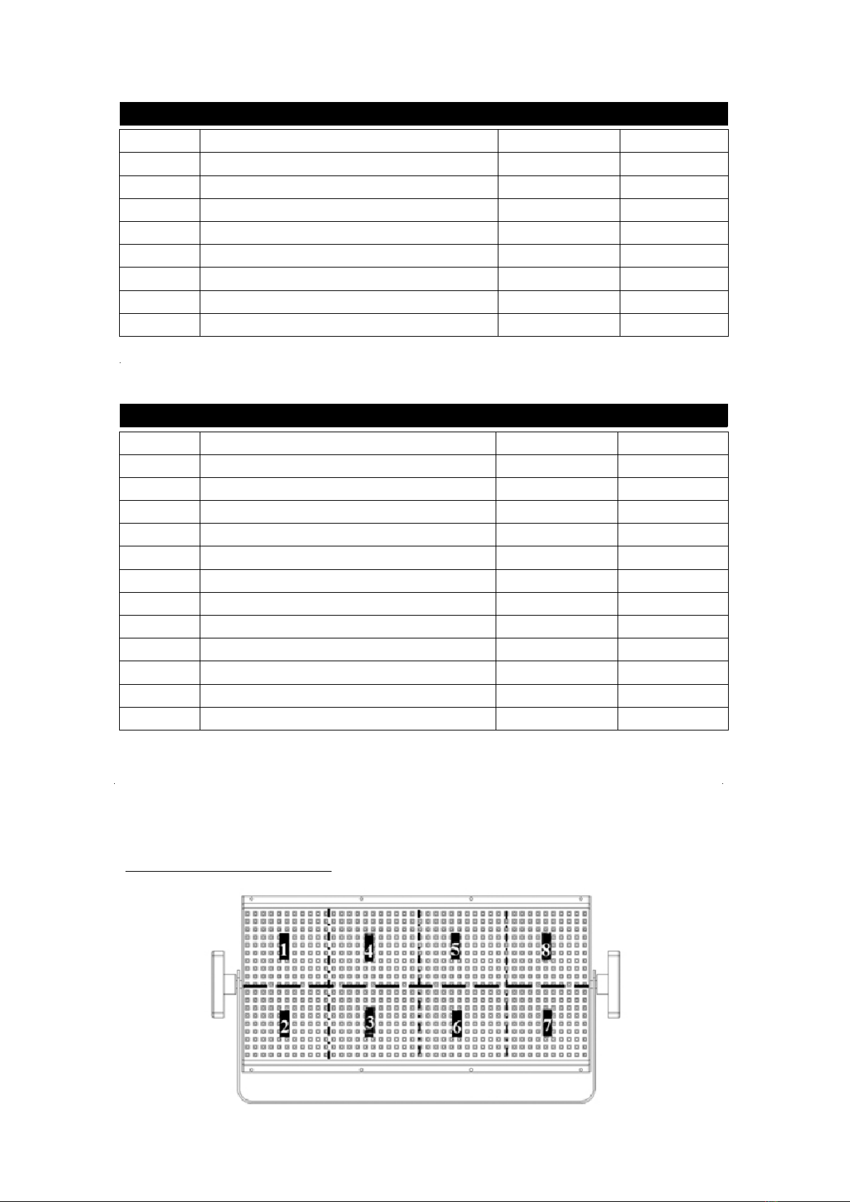
Each unit has 8 individually addressable segments of display for stunning visual
patterns, with 51 built in programs for quick easy use and standalone use. The unit can
be set to run from DMX or used as a stand alone strobe with operational values set on
the LCD rear display
Power is via Powercon in and out and DMX is available on both 3 and 5 pin XLR in
and out
The unit is therefore ideal for use not only as a strobe but as a magic LED colour wall
or even a colour or white wash light.
Specifications.
Light Source: Super bright LED 0.5w
Total LEDs: 1056pcs, 132 in each segment
Colour Temp White Version:5000K
8 individually controllable segments
Power input: 110V~220V,50Hz~60Hz
Power consumption: 268w
Power in / out on Powercon connectors
DMX on both 3 and 5 pin in / out connectors
Fused with 10a 20mm external fuse
DMX Modes 1/5/8/12 White version
DMX Modes 2/7/16/28 RGB version
Linear smooth dimming 0-100%
Strobe frequency 0-650 ms @ 50 Hz AC
Viewing Angle 95° (White version) 120° (RGB version)
52 Built in Macro Shows
Quick Lock design to build into large displays
Vertical Hanging by Half/Coupler (multiple locked units)
Angled Hanging by Trunion Arm & Hook Clamp (single unit)
LCD Apha-numeric backlit Panel for light settings
Weight: 4Kg
Size: 225 x 445 x100 mm (H/W/D)

Safety Information
!
Strobe lights are known to trigger epileptic seizures in persons who are photosensitive.
This product must be installed by a competent person familiar with the construction and
operation of the product and the hazards involved. Warning notices that strobe lighting will be
used in the performance should be on view at the entrances to the venue
•
Do not open: there are no user-serviceable parts inside.
•
Always ground (earth ) the fixture electrically.
•
Use only a source of AC power that compiles with local building and electrical codes and has
both overload and earth leakage protection.
•
Do not expose the fixture to rain or moisture - it is suitable for indoor or covered use only
!
•
Do not stare directly into the light.
•
Never attempt to bypass the fuse. Always replace defective fuses with ones of the specified type
and rating.
•
Verify that the power feed cable is rated for the current draw of all connected fixtures.
•
Keep all combustible materials (for example fabric, wood, paper) at least 0.5 meters (20 inches)
away from the fixture. Keep flammable materials well away from the fixture.
•
Provide a minimum clearance of 0.1 meters (4 inches) around air vents.
•
Do not modify the fixture or install other than genuine Viking parts.
•
Do not operate the fixture if the ambient air temperature exceeds 40
˚
C (104
˚
F).
•
Caution: Exterior surface temperature after 5 min. operation can reach 40
˚
C (104
˚
F)
WARNING!
This product is for professional use only! It is not for household use
To guard against electric shock
To guard against UV radiation, burn, and fire.

Preparation for Use
Preparation for Use
Unpacking
• Strobe Light Fixture
• User manual
• DMX cable
• Mains power cable
• Trunion Arm Bracket, 2 Arm Knobs, Half Coupler Bracket & Hex Screws, Safety Eye
The packing material protects the fixture during shipment, please retain for future transportation of
the fixture.
AC Power Connection
The auto-ranging power supply automatically adjusts to AC power from 208-240 volts nominal at
50/60 Hz.
The current required by the light is 4 amps. To avoid overload, allow one 4 amp branch circuit per
fixture to operate the light model at full power.
Use 2.5 mm2 (13 AWG) or larger power feed cables and keep runs as short as possible.
The power cable colur coding is given in the table.
• Connect the brown wire to live
• Connect the blue wire to neutral
• Connect the green/yellow wire to ground (earth)
The device must be grounded / earthed and be able to be isolated from AC power. The AC
power supply must incorporate a fuse or circuit breaker for fault protection.
To rig the fixture
!
Before installing;
•
Verify that the attachment hardware is in good condition and designed to carry at least 10 times
the fixture’s weight.
•
Verify that the structure can support at least 10 times the weight of all installed fixtures, clamps,
cables, auxiliary equipment, etc.
•
Verify that the clearance around the air vents is at least 0.1 meters (4 in.).
•
Loosen the mounting bracket and adjust the fixture to the desired angle.
•
Connect and arrange the power and data cables.
•
Use a safety bond if 15kg rating or higher and wrap around the Trunion Arm for single units or
attach the Safety Eye to Trunion Arm Mounting Hole if building into multiple displays
Always use a secure means of secondary fixing such as a safety wire

Controller Operation
This section describes how to operate the light with a DMX controller.
Data Connection
The light provided 3-Pin
、
5-pin XLR connectors for data connection. The pin-out on all connectors
is pin 1 to shield, pin 2 to cold (-), and pin 3 to hot (+).
There is no connection to pins 4 and 5.
To connect the data link
1. Connect the DMX data output from the controller to the fixture XLR input (male) socket.
2. Connect up to 31 additional fixtures output-to-input.
3. Insert a termination plug in the output of the last fixture on the link.
Data Connection Tips
•
Use DMX cable designed for DMX devices: standard microphone cable can be used for short
runs of up to 100m over long distance we recommend using true DMX cables and ALWAYS
terminate the single on the last unit in the line with a Terminator
•
Do not overload the link. Up to 32 devices may be connected on a serial link.
• Terminate the link by installing a termination plug in the output socket of the last fixture. The
termination plug, which is a male XLR with a 120 ohm 0.25 watt resistor soldered between
pins 2 and 3, absorbs the control signal so it does not reflect and cause interference.
Quicklock installation
•
Each Top Units must hang with half coupler clamps on the solid truss or bar.
•
On a 240v supply, to 5 units can have the power daisy chained
•
On a 120v supply, to 3 units can have the power daisy chained
•
Quicklock parts are inside each light, make sure each part is well locked
•
Quicklock parts are aluminium, please don’t abuse them by over tightening
•
Quicklock parts may have lubricant on them, please don’t clean
•
Make sure all lights are level when screwing up the Quicklock
•
Each Quicklock fixing screws into the mating connector - do not overforce screw
Ask for Quicklock help from from the dealer if needed

Function set - Menu Map
Press MENU button to view the menus
,
press ENTER button to choose the
menu
,
press UP/DOWN button to view the function
,
press ENTER button to choose
。
To go back to main menu, please press MENU button
。
Menu chart:
Main Menu
Function Function
DMX Mode
Function
Show Mode
Function
DMX Address
Function
Channel Mode
Function
Manual
Function
System
Function
DMX Address
A
:
001
Channel Mode
02 Channels
Function
Show Select
Show Select
Show
:
01
Function
Show Speed
Show Speed
Show
:
01
Manual
Green
:
000
Manual
Blue
:
000
Manual
Red
:
000
Manual
Ratio
:
000
Manual
Sterobe
:
000
Function
Show Speed
Function
Show Select
Manual
Macro
:
000

3 Channel mode
Channel Function Value Percent
1
Master Dimmer
2
RGB and RGB mix
3 Strobe speed 0.5 to 25 times / sec
0 -255 0-100
0 -255 0-100
0 -255 0-100
8 Channel mode
Channel Function Value Percent
1
Master Dimmer
0-255 0-100
2
red
0-255 0-100
3
green
0-255 0-100
4 blue 0-255 0-100
5 Strobe speed 0.5 to 25 times / sec 0-255 0-100
0-255 0-100
6 Strobe frequency 15-255 0-100
7 Marcos 0-255 0-255
8 Marcos speed 0-255 0-100
17 Channel mode
Channel Function Value Percent
1 Master Dimmer 0-255 0-100
2 Seg 1 and seg 2 Red 0-255 0-100
3 Seg 1 and seg 2 Green 0-255 0-100
4 Seg 1 and seg 2 Blue 0-255 0-100
5 Seg 3 and seg 4 Red 0-255 0-100
6 Seg 3 and seg 4 Green 0-255 0-100
7 Seg 3 and seg 4 Blue 0-255 0-100
8 Seg 5 and seg 6 Red 0-255 0-100
9 Seg 5 and seg 6 Green 0-255 0-100
10 Seg 5 and seg 6 Blue 0-255 0-100
11 Seg 7 and seg 8 Red 0-255 0-100
12 Seg 7 and seg 8 Green 0-255 0-100
13 Seg 7 and seg 8 Blue
14 Strobe speed 0.5 to 25 times / sec 0-255 0-100
0-255 0-100
15 Strobe frequency 15-255 0-100
16 Marcos 0-255 0-255
17 Marcos speed 0-255 0-100
DMX Protocol
RGB version

29 Channel mode
1 Channel mode
Channel Function Value Percent
1
General dimmer 0-05 0-100
Strobe speed 0.5 times / sec-25 times / sec 06-255 0-100
Marcos 201-255 0-xxx
5 Channel mode
Channel Function Value Percent
1
General dimming
0-255 0-100
2 Strobe speed 0.5 times / sec-25 times / sec 0-255 0-100
3 Strobe frequency 15-255 0-100
4 Marcos 0-255 0-100
5 Marcos speed 0-255 0-100
DMX Protocol
White version
Channel Function Value Percent
1 Master Dimmer 0-255 0-100
2 Segment 1 Red 0-255 0-100
3 Segment 1 Green 0-255 0-100
4 Segment 1 Blue 0-255 0-100
5 Segment 2 Red 0-255 0-100
6 Segment 2 Green 0-255 0-100
7 Segment 2 Blue 0-255 0-100
8 Segment 3 Red 0-255 0-100
9 Segment 3 Green 0-255 0-100
10 Segment 3 Blue 0-255 0-100
11 Segment 4 Red 0-255 0-100
12 Segment 4 Green 0-255 0-100
13 Segment 4 Blue 0-255 0-100
14--25 Seg 5 Red- - -Seg 8 Blue 0-255 0-100
26 Strobe speed 0.5 to 25 times / sec 0-255 0-100
27 Strobe frequency 15-255 0-100
28 Marcos 0-255 0-255
29 Marcos speed 0-255 0-100

8 Channel mode
12 Channel mode
Channel Function Value Percent
1
Seg 1 and seg 2 dimmer
0-255 0-100
2
Seg 3 and seg 4 dimmer
0-255 0-100
3
Seg 5 and seg 6 dimmer
0-255 0-100
4
Seg 7 and seg 8 dimmer
0-255 0-100
5 Strobe speed 0.5 times / sec-25 times / sec 0-255 0-100
6 Strobe frequency 15-255 0-100
7 Marcos 0-255 0-100
8 Marco speed 0-255 0-100
Channel Function Value Percent
1
Segment 1 dimmer
0-255 0-100
2
Segment 2 dimmer
0-255 0-100
3
Segment 3 dimmer
0-255 0-100
4
Segment 4 dimmer
0-255 0-100
5
Segment 5 dimmer
0-255 0-100
6
Segment 6 dimmer
0-255 0-100
7
Segment 7 dimmer
0-255 0-100
8
Segment 8 dimmer
0-255 0-100
9 Strobe speed 0.5 times / sec-25 times / sec 0-255 0-100
10 Strobe frequency 15-255 0-100
11 Marcos 0-255 0-xxx
12 Marcos speed 0-255 0-100
Segments
All versions
Specifications subject to change without notice
Table of contents
Other Viking Stage Lighting Dj Equipment manuals

Viking Stage Lighting
Viking Stage Lighting VK918 User manual

Viking Stage Lighting
Viking Stage Lighting VK1810 User manual

Viking Stage Lighting
Viking Stage Lighting VK540 SURGE WALL WASH User manual

Viking Stage Lighting
Viking Stage Lighting VK740 MK2 User manual

Viking Stage Lighting
Viking Stage Lighting VK301 Vivid User manual
Popular Dj Equipment manuals by other brands

Wiedamark
Wiedamark IRDE-14001B4-00D-13 user manual

Briteq
Briteq BTX-LIGHTSTRIKE Operation manual

Chauvet
Chauvet COLORado Batten 144 Tour Quick reference guide

EuroLite
EuroLite LED CBB-2 user manual

Audio-Visual Station
Audio-Visual Station AVS-3210CYC user manual

Iluminarc
Iluminarc LOGIC AR111 Downlight S Quick reference guide