Owner’s Manual
Aircon / Heating - 72 Viking Sport Cruiser 61FY
v1.0
••••••••••••••••••••••••••••••••••••••••••••••••••••••
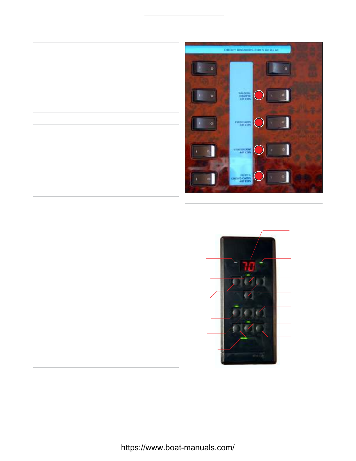
Check voltage and
load – 240 volts
Reduce load if a A/C
breaker. With an Iso-Boost
transformer and 100 amp
service, low voltage should not be a problem, but you
may be unable to switch on all units. Remember as
voltage decreases amperage increases.
The SMX units also display error codes (see SMX
manual for details). System fault codes are displayed
if, for example, compressors are overheating because
the seawater strainer is partially blocked with weeds.
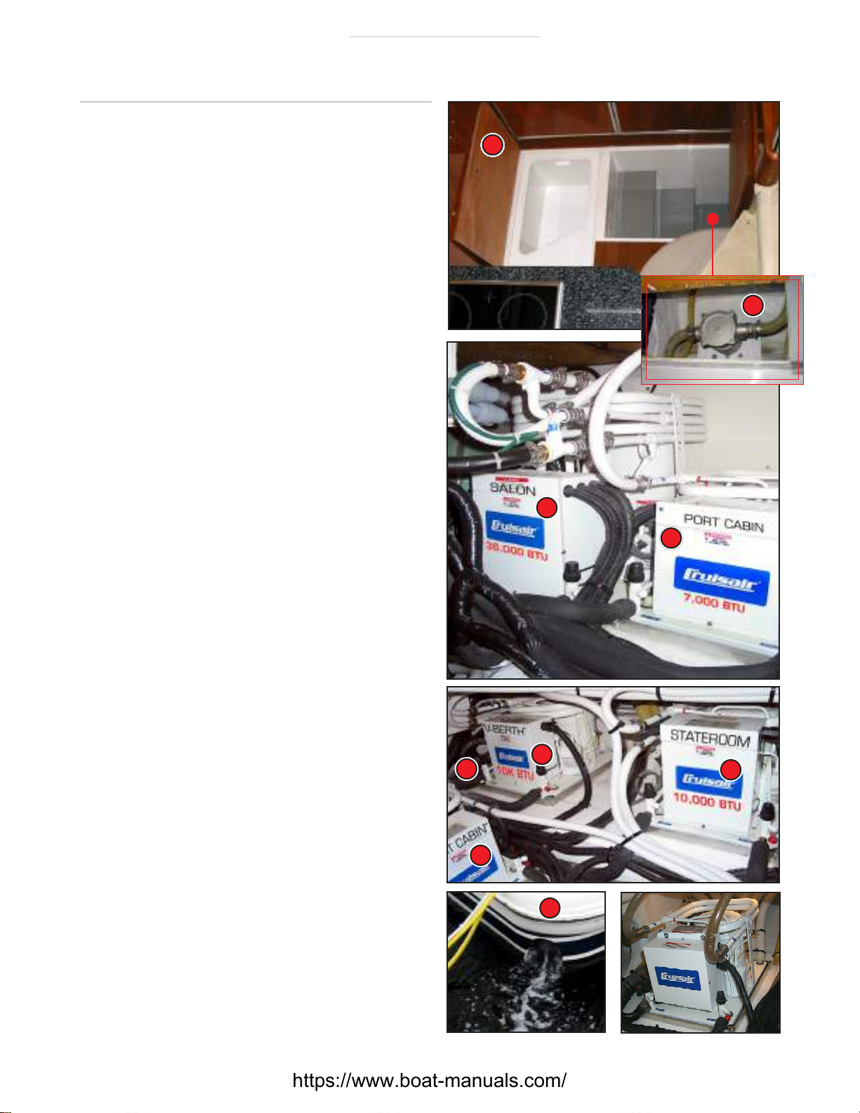
To clean the seawater strainer. . .
•Switch off ALL breakers for the A/C system.
•Close seacock S. Have a dish handy to dump sea-
water and debris from the strainer into it.
•Loosen the four bolts holding the cap B.Seawater
will come out. Avoid getting seawater into the com-
partment by having an absorbent cloth around the
cap. Ease up and remove bolts and cap.
•Remove the internal screen. Clean out all weeds
and other debris.
•Replace the screen and cap, tighten down the nuts.
•Open the seacock S; the strainer should quickly fill
with seawater. Check the cap for leaks. If OK, switch
the system on.
•Check again to ensure there are no leaks.
•Check that discharge
flow is normal.
Regularly check the A/C strainer
for weeds and other debris.
Remember – this is below the
waterline! So shut the seacock.
Troubleshooting the System
One of the advantages of a direct expansion system is its
simplicity. It depends simply on:
•an unobstructed supply of seawater,
•correct voltage,
•free flowing air supply to the return air grilles, and
•unobstructed air discharge ducts.
Any one of these items that is not up to par will give you
a problem.
If the air conditioner is running in weedy water, the strainer
can quickly fill with weeds. Don’t neglect to regularly check
the A/C strainer for weeds, sea urchins and other debris. If
anything gets through the strainer it can slow down the
magnetic drive to the pump. However, the strainer will not
stop sand, and that may damage the seawater pump. Over
time, sand in the water can erode the double wall pipe
above the compressor.
Also be aware that suction at the thru-hull may attract
plastic junk in the water, preventing seawater getting to
the pump. Get to know the normal appearance of dis-
charge from the compressors through the engine exhaust
so you can tell if flow is reduced.
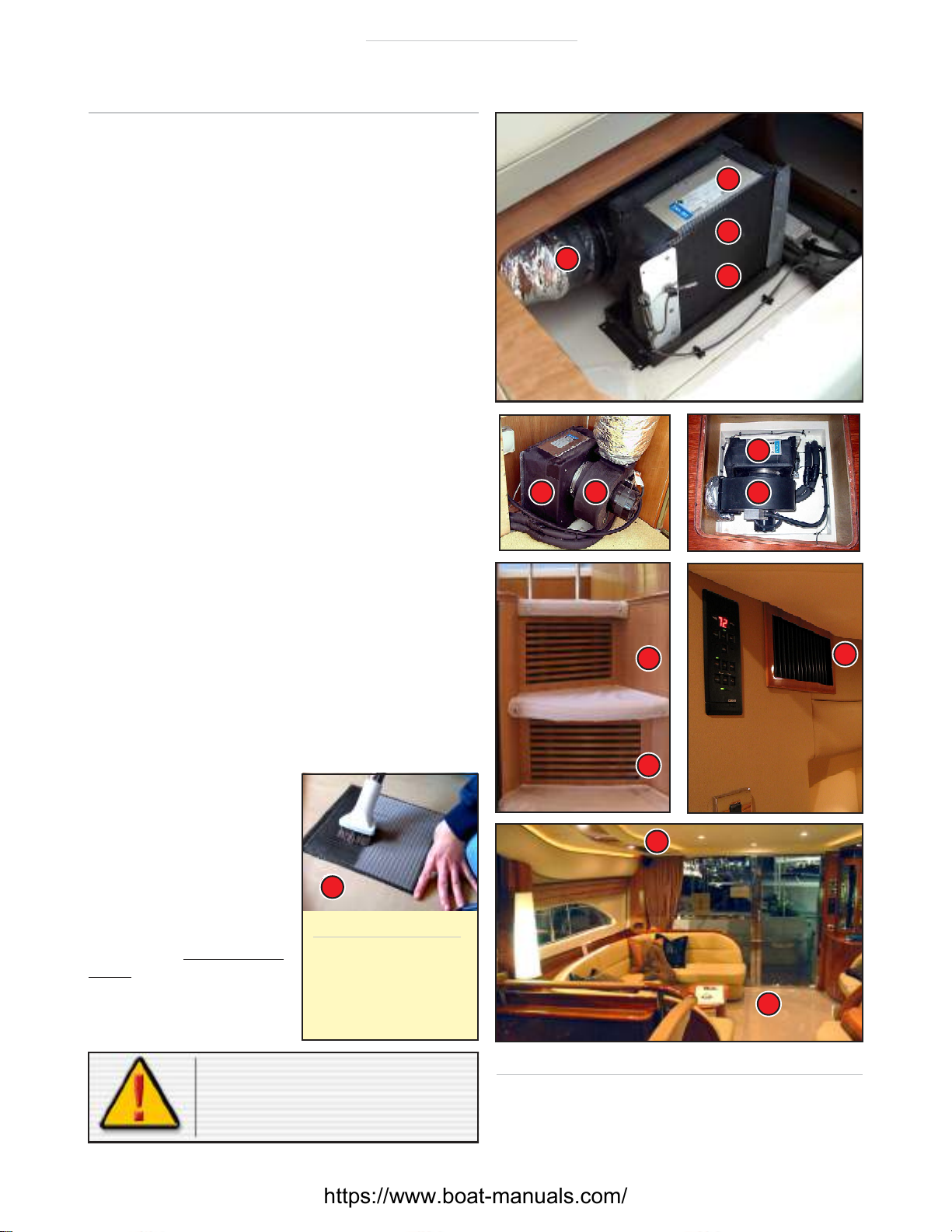
Do NOT obstruct the return air grilles with furniture, cush-
ions or newspapers. If air cannot get through obviously
the air in the cabin cannot be cooled or heated.
The same thing happens if the air filter screen behind the
return air grille is not cleaned – very quickly dust builds
up, starving the system of free flowing air. You should
check screens every two weeks if the vessel is in con-
stant use, monthly if not.
Check the dock voltage, if it is low, below 205 volts, you
should be selective in how many units you run or, if cool-
ing, set them at a higher temperature.
If you leave the system on when you are away for a few
days, arrange for someone to check that it is operating
properly (and leave the SHOWER DISCHARGE PUMP on).
These are very simple checks – if they are done the sys-
tem will perform as designed, and maintain a constant
pleasant temperature throughout the vessel.
S
B
S
https://www.boat-manuals.com/