Viking VCCC115-SS81A Installation manual

USER GUIDE & SERVICE MANUAL
®
Model: VCCC115-SS81A

USER GUIDE & SERVICE MANUAL
Table of Contents
Click on any section below to jump directly there
Intro
Safety
Safety and Warning
Disposal And Recycling
Installation
Environmental Requirements
Electrical
Cutout & Product Dimensions
Side by Side Installation
Water Hookup
Drain
General Installation
Grille Installation
Door Swing
Door Adjust
Maintenance
Cleaning
Cleaning Condenser
Extended Non-Use
Operating Instructions
First Use
Control Operation
Ice
Airflow and Product Loading
Service
Troubleshooting
Wire Diagram
Product Liability
Parts
R600a Specifications
System Diagnosis Guide
Compressor Specifications
Control Operation - Service
Thermistor
Warranty

USER GUIDE
Introduction
WELCOME TO VIKING COMMERCIAL
Congratulations on your purchase!
Viking is synonymous with decades of innovation and craftsmanship. Our industry-leading appliances set the standards.
Delivering professional performance and stunning design. Our products have become the standard for elite chefs around the
world.
PRODUCT INFORMATION
Looking for additional information on your product? User Guides, Spec Sheets, and Product Warranty information are available
online at vikingrange.com/commercial.
PROPERTY DAMAGE / INDUSTRY CONCERNS
In the unlikely event property damage or personal injury is suspected related to a Viking Commercial product, please take the
following steps:
1. Customer Care must be contacted at +1.616.754.5601
2. Service or repairs performed on the unit without prior written approval is not permitted. If the units have been
alteredorrepairedintheeldwithoutpriorwrittenapproval,claimswillnotbeeligible.
GENERAL INQUIRIES
1260 E. Van Deinse • Greenville, MI 48838 •
+1.616.754.5601
Website: vikingrange.com/commercial
commercial@vikingrange.com
CONNECT WITH US
SERVICE & PARTS ASSISTANCE
Monday – Friday 8:00 am to 4:30 pm CST
+1.616.754.5601
Service Email: commercialservice@vikingrange.com
3

USER GUIDE
Safety and Warning
Safety and Warning
NOTICE
Please read all instructions before installing,
operating, or servicing the appliance.
Use this appliance for its intended purpose only and follow
these general precautions with those listed throughout this
guide:
SAFETY ALERT DEFINITIONS
Throughout this guide are safety items labeled with a
Danger, Warning, or Caution based on the risk type:
Danger means that failure to follow this safety
statement will result in severe personal injury or
death.
Warning means that failure to follow this safety
statement could result in serious personal injury
or death.
Caution means that failure to follow this safety
statement may result in minor or moderate
personal injury, property, or equipment damage.
This unit contains R600a (Isobutane) which is a
ammable hydrocarbon. It is safe for regular
use. Do not use sharp objects to expedite
defrosting. Do not service without consulting the
“R600a specications” section included in the
User Guide. Do not damage the refrigerant
circuit.
Service must be done by factory authorized
service personnel. Any parts shall be replaced
with like components. Failure to comply could
increase the risk of possible ignition due to
incorrect parts or improper service.
CALIFORNIA PROPOSITION 65
This product contains chemicals known to the
state of California to cause cancer and birth
defects or other reproductive harm.
www.P65warnings.CA.gov
This equipment is to be installed with adequate
backow protection to comply with applicable
federal, state and local codes.
DANGER
!
DANGER
!
WARNING
!
CAUTION
!
CAUTION
!
WARNING
!
4

USER GUIDE
Disposal and Recycling
RISK OF CHILD ENTRAPMENT. Before you throw
away your old refrigerator or freezer, take o
the doors and leave shelves in place so children
may not easily climb inside.
If the unit is being removed from service for disposal,
check and obey all federal, state, and local regulations
regarding the disposal and recycling of refrigeration
appliances, and follow these steps completely:
1. Remove all consumable contents from the unit.
2. Unplug the electrical cord from its socket.
3. Remove the door(s)/drawer(s).
DANGER
!
5

USER GUIDE
Environmental Requirements
This model is intended for indoor/interior applications only
and is not to be used in installations that are open/
exposed to natural elements.
This unit is designed to operate between 50°F (10°C) and
100°F (38°C). Higher ambient temperatures may reduce
the unit’s ability to reach low temperatures and/or reduce
ice production on applicable models.
For best performance, keep the unit out of direct sunlight
and away from heat generating equipment.
In climates where high humidity and dew points are
present, condensation may appear on outside surfaces.
This is considered normal. The condensation will
evaporate when the humidity drops.
CAUTION
!
Damages caused by ambient temperatures of
40°F (4°C) or below are not covered by the
warranty.
6

USER GUIDE
Electrical
Electrical
WARNING
!
SHOCK HAZARD — Electrical Grounding
Required. Never attempt to repair or perform
maintenance on the unit until the electricity has
been disconnected.
Never remove the round grounding prong from
the plug and never use a two-prong grounding
adapter.
Altering, cutting or removing power cord,
removing power plug, or direct wiring can cause
serious injury, fire, loss of property and/or life,
and will void the warranty.
Never use an extension cord to connect power to
the unit.
Always keep your working area dry.
NOTICE
Electrical installation must observe all state and
local codes. This unit requires connection to a
grounded (three-prong), polarized receptacle
that has been placed by a qualified electrician.
The unit requires a grounded and polarized 115 VAC,
60 Hz, 15A power supply (normal household current). An
individual, properly grounded branch circuit or circuit
breaker is recommended. A GFCI (ground fault circuit
interrupter) is usually not required for fixed location
appliances and is not recommended for your unit because
it could be prone to nuisance tripping. However, be sure
to consult your local codes.
See CUTOUT & PRODUCT DIMENSIONS for recommended
receptacle location.
7

USER GUIDE
Cutout & Product Dimensions
PREPARE SITE
Your product has been designed for either free-standing
or built-in installation. When built-in, your unit does
not require additional air space for top, sides, or rear.
However, the front grille must NOT be obstructed, and
clearance is required for an electrical connection in
the rear.
CAUTION
!
Unit can NOT be installed behind a closed cabinet
door.
If you would like to align the face of the unit with
other adjacent cabinet doors, you may need to
alter the wall just behind the drain connection on
the unit to accommodate the drain.
CUTOUT DIMENSIONS
PRODUCT DIMENSIONS
REAR
FRONT
TOP
SIDE
4"
(102 mm)
7"
(178 mm)
15"
(381 mm)
Preferred location
for electrical outlet
is in adjacent
cabinet.
24"
(610 mm)
5⁄8"
(16 mm)
31 ⁄” to 32 ⁄”
(794 mm to
819 mm
27 ⁄”
(711 mm)
3 ⁄”
(89 mm)
1 ⁄”
(32 mm)
Drain
Water In
Power
Cord
6 ⁄”
(175 mm)
3 ⁄”
(89 mm)
1 ⁄”
(44 mm)
4 ⁄”
(105 mm)
14 ⁄”
(378 mm
33 ⁄” to 34 ⁄”
(794 mm to
819 mm
3 ⁄”
(95 mm
27 ⁄”
(711 mm)
21 ⁄”
(537 mm
16”
(406 mm
37 ⁄”
(406 mm
3
”
( mm
27 ⁄”
(711 mm)
MECHANICAL
AREA
ICE STORAGE
BIN
ICE CREATION
AREA
25 ⁄”
(648 mm 23 ⁄”
(610 mm
2 ⁄ ”
(54 mm
9”
(711 mm)
8

USER GUIDE
Side-by-Side Installation
OTHER SITE REQUIREMENTS
Side-by-Side Installation
Units must operate from separate, properly grounded
electrical receptacles placed according to each unit’s
electrical specications requirements.
Cutout width for a side-by-side installation is the total of
the widths listed under Cutout Dimensions in each unit’s
Installation Guide. Each door can be opened individually
(one at a time) without interference.
However, to ensure unobstructed door swing (opening both
doors at the same time), 1/4” (6.4 mm) of space needs to
be maintained between the units.
Hinge-by-Hinge Installation (Mullion)
When installing two units hinge-by-hinge, 13/16” (22 mm)
is required for integrated models. Additional space may be
needed for any knobs, pulls or handles installed.
Stainless steel models which include the standard stainless
handle will require 4-9/16” (116 mm) to allow both doors to
open to 90° at the same time.
1⁄4” (6 mm)
⁄” (22 mm
⁄” (116 mm
9

USER GUIDE
Water Hookup
Water Hookup
WATER SUPPLY
Observe and follow all local building codes when installing
this appliance.
This ice machine must be connected to a potable cold
water supply line. delivering water pressure between a
minimum of 20 psi and a maximum of 120 psi.
Use 1⁄4” copper tubing for your water supply which is
available at any local hardware or plumbing supply store.
Route the 1⁄4” copper tubing to suit your installation being
sure not to kink the tubing. Purchase enough copper
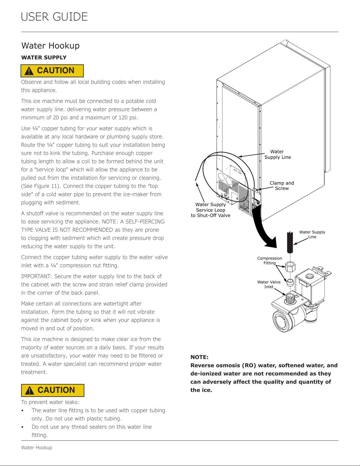
tubing length to allow a coil to be formed behind the unit
for a “service loop” which will allow the appliance to be
pulled out from the installation for servicing or cleaning.
(See Figure 11). Connect the copper tubing to the “top
side” of a cold water pipe to prevent the ice-maker from
plugging with sediment.
A shuto valve is recommended on the water supply line
to ease servicing the appliance. NOTE: A SELF-PIERCING
TYPE VALVE IS NOT RECOMMENDED as they are prone
to clogging with sediment which will create pressure drop
reducing the water supply to the unit.
Connect the copper tubing water supply to the water valve
inlet with a 1⁄4” compression nut tting.
IMPORTANT: Secure the water supply line to the back of
the cabinet with the screw and strain relief clamp provided
in the corner of the back panel.
Make certain all connections are watertight after
installation. Form the tubing so that it will not vibrate
against the cabinet body or kink when your appliance is
moved in and out of position.
This ice machine is designed to make clear ice from the
majority of water sources on a daily basis. If your results
are unsatisfactory, your water may need to be ltered or
treated. A water specialist can recommend proper water
treatment.
To prevent water leaks:
•The water line tting is to be used with copper tubing
only. Do not use with plastic tubing.
• Do not use any thread sealers on this water line
tting.
NOTE:
Reverse osmosis (RO) water, softened water, and
de-ionized water are not recommended as they
can adversely affect the quality and quantity of
the ice.
CAUTION
!
CAUTION
!
Water
Supply Line
Clamp and
Screw
Water Supply
Service Loop
to Shut-Off Valve
Water Valve
Inlet
Compression
Fitting
Water Supply
Line
10

USER GUIDE
Drain
The oor drain must be large enough to
accommodate drainage from all attached drains.
Follow these guidelines when installing drain
lines to prevent water from owing back into
the ice maker storage bin and/or potentially
owing onto the oor, which may result in
personal injury or property damage
Failure to connect water supply or drain line
connections properly can result in personal injury
and property damage. Gravity drain connections
must be routed downward from the rest of the
unit at the rate of 1/4” per foot (1 cm per 50 cm).
Drain can NOT be located directly below the
unit. Unit has a solid base that will not allow the
unit to drain below itself.
There is a possibility that hose connections may
have loosened during shipment.
Verify all connections and ttings are free from
leaks.
This equipment is to be installed with adequate
backow protection to comply with applicable
federal, state and local codes
DRAIN CONNECTION
NOTICE
Drain
CAUTION
!
CAUTION
!
CAUTION
!
Cold
Water
Hot
Water
Waste
Waste
Shut-Off
Valve
Air Gap
(Optional Hook-Up)
Cold
Water
Hot
Water
Waste
Shut-Off
Valve
The maximum lift for the drain pump is
10 feet. This must be done as close to the rear of
the unit as possible.
NOTICE
Waste
Cold
Water
Shut-Off
Valve
Hot
Water
Air Gap
(Optional Hook-Up)
Drain pump
vent tube.
Keep this open
to assure
air flows freely
as water
enters the
pump reservoir.
Drain line coiled and
secured to the back of the
cabinet. Uncoil, route to
an appropriate drain, and
and cut to length.
11

USER GUIDE
General Installation
LEVELING INFORMATION
1. Use a level to
conrm the unit is
level. Level should
be placed along top
edge and side edge
as shown.
2. If the unit is not level, adjust the legs on the corners of
the unit as necessary.
3. Conrm the unit is level after each adjustment and
repeat the previous steps as needed.
INSTALLATION TIP
If the room oor is higher than the oor in the cutout
opening, adjust the rear legs to achieve a total unit rear
height of 1⁄8” (3 mm) less than opening’s rear height.
Shorten the unit height in the front by adjusting the front
legs. This allows the unit to be gently tipped into the
opening. Readjust the front legs to level the unit after it is
correctly positioned in the opening.
INSTALLATION
1. Plug in the power/electrical cord.
2. Gently push the unit into position. Be careful not
to entangle the cord or water and drain lines, if
applicable.
3. Re-check the leveling, from front to back and side to
side. Make any necessary adjustments. The unit’s top
surface should be approximately 1⁄8” (3 mm) below
the countertop.
4. Remove interior packing material and wipe out the
inside of the unit with a clean, water-dampened cloth.
1
Turn to Adjust
12

USER GUIDE
Grille Installation
Grille Installation
REMOVING AND INSTALLING GRILLE
Disconnect electric power to the unit before
removing the grille.
When using the unit, the grille must be installed.
Do NOT touch the condenser ns. The condenser
ns are SHARP and can be easily damaged.
Removing the grille
1. Disconnect power to the unit.
2. Remove the two screws.
3. Remove grille from unit.
Installing the grille
1. Align cabinet and grille holes and secure, but do not
over tighten grille screws.
2. Reconnect power to the unit.
WARNING
!
WARNING
!
Condenser
Screws
13

USER GUIDE
Door Swing
USER GUIDE
Door Swing 1
u-line.com
SAFETY • INSTALLATION & INTEGRATION • OPERATING INSTRUCTIONS • MAINTENANCE • SERVICE
Door Swing
Wall Wall
90
Door Swing
90
Door Swing
2-1/8" Min.
(54 mm)
1/4" Min.
(6 mm)
Units have a zero clearance for the door to open 90°,
when installed adjacent to cabinets.
Stainless Steel and black and white models require
2-1/8" (54 mm) door clearance to accommodate the
handle if installed next to a wall.
Integrated models require 1/4" (6 mm) clearance if
installed next to a wall. Allow for additional space for any
knobs or pulls installed on the integrated panel/frame.
14

USER GUIDE
Door Adjustments
2. With a Phillips screwdriver, remove the bushing screw
and hing pin from the bottom hinge.
3. Remove the cam closer from the lower hinge bracket
and save.
4. Using a 5/32” hex key, remove the upper and lower
hinge brackets from the door, saving all components.
5. Remove black plugs from opposite side of door, ip the
upper hinge bracket and reattach the hinge bushing
and screw into place on the opposite side of door
(where
plugs were
removed.)
6. Reattach
the upper
and lower
hinges
and hinge
brackets
to the
opposite
sides.
Door Adjustments
REVERSING THE DOOR
Location of the unit may make it desirable to mount the
door on the opposite side of the cabinet.
The hinge hardware will be removed and reinstalled on the
opposite side of the cabinet.
TO REVERSE THE DOOR
Note: When reversing the door, the top hinge
becomes the bottom hinge on the opposite side
of the unit - likewise, the bottom hinge becomes
the top on the other side.
REMOVE DOOR
1. Remove hinge pin from upper hinge using a 1/8” hex
key tool, making sure to steady the door.
2. Let the door tilt forward and lift door from bottom
hinge.
REMOVE HINGES
1. Using a Phillips screwdriver,
remove the 6 screws from
both the upper and lower
hinges and save for later
steps.
Hinge Pin
Upper Hinge
Plate
Hinge Pin
Bushing
Screw
Cam
Closer
Left-Hand
Hinged Door
Right-Hand
Hinged Door
Hinge Pin
Bushing
Upper Hinge
Plate
Lower Hinge
Plate
Cam Closer
and screw
15

USER GUIDE
Door Adjustments
7. Using a Phillips screwdriver, remove the toe kick from
the door and attach it to the opposite side.
8. Reinstall the door.
Toe Kick
Reversal
16

USER GUIDE
First Use
u-line.com
First Use
Initial startup requires no adjustments. See CONTROL
OPERATION section for more details.
NOTICE
Discard the ice produced during the first two or
three hours of operation to avoid possible dirt or
scale that may dislodge from the water line.
When plugged in, the unit will begin operating under the
factory default settings. If the unit was turned off during
installation, simply press and the unit will immediately
switch on. To turn the unit off, press and release.
17

USER GUIDE
Control Operation
Control Operation
USING YOUR ELECTRONIC CONTROL
Control Function Guide
Function Command Notes
ON/OFF Press and release. Unit will immediately turn ON or OFF.
Enable Sabbath Mode Press and hold for 5 seconds and release.
The oF / oC symbol will ash briey after 5 seconds. Interior
light and display will go dark and remain so until user resets
mode - unit continues to operate.
Disable Sabbath Mode Press and release. Display and interior light return to normal operation.
Silent Mode (ice production
suspended for 3 hours) Hold and .Display will count down the hours:
Clean Mode See "Cleaning" section
Showroom Mode Hold and for 5 seconds.
The oF / oC symbol will ash. Display will be lit and interior light
will function. Unit will not cool. Repeat command to return to
normal operation.
Door Alert Notication
When the door is left open for more than 30 minutes:
• A tone will sound for several seconds every minute
• will appear in display
• Close door to silence alert and reset
First Use
Initial startup requires no adjustments. When plugged in, the unit will
begin operating under the factory default settings. If the unit was turned o
during installation, simply press and the unit will immediately switch on.
To turn the unit o, press .
Temperature displayed reects actual temperature inside unit. If the
temperature displayed is dierent than selected, the unit is progressing
towards the selected temperature. Time to reach set point varies based
upon ambient temperature, temperature of product loaded, door openings,
etc. Marvel recommends allowing the unit to reach set points before
loading.
NOTE
Electronic control
Hidden
Button
18

USER GUIDE
Control Operation
BrightShield™
This model includes BrightShield™ with Vyv™ Antimicrobial Light Technology.
BrightShield™
• Kills* and prevents the growth of viruses, bacteria, fungi, yeasts, mold, and mildew
• Provides continuous antimicrobial action to keep surfaces clean
• Is approved for continuous use around people, pets, & plants
• Reduces odors caused by bacteria, fungi, yeasts, mold, and mildew
• Creates a cleaner environment for food, beverages, & ice
BrightShield™ is most eective when used continuously. Your unit is factory-set to use BrightShield™ lighting
whenever the door is closed and standard bright white when the door is open. See Control Operations sections for
details and other options.
For more information about BrightShield™ visit www.u-line.com.
For more information about Vyv™ Antimicrobial Light Technology visit www.vyv.tech.com
* Testing on a non-enveloped virus (MS2 bacteriophage) showed a 97.12% reduction in controlled laboratory testing in 8 hours on hard
surfaces. Testing on SARS-CoV-2 (enveloped virus) showed a 98.45% reduction in controlled laboratory testing in 4 hours on hard surfaces.
Testing on MRSA E. coli showed 90%+ reduction in controlled laboratory testing in 24 hours on hard surfaces. Results may vary depending on
the amount of light that is reaching the surfaces in the space where the product is installed and the length of time of exposure. Use of Vyv™
Antimicrobial Light Technology is not intended to replace manual cleaning and disinfection practices.
19

USER GUIDE
First Use
ICE
Your ice machine is unique in how it forms ice with
fractional freezing to form a slab of ice that is clear and
has less dissolved solids than the water from which it is
produced. This is accomplished by running water over the
cold evaporator plate which gradually freezes the water to
produce the ice slab. Pure water freezes rst, leaving the
dissolved solids in the residual reservoir water.
When the ice slab reaches the correct thickness, the ice
sheet is released and slides onto the grid cutter. There,
the ice slab is cut into cubes by the grid cutter’s heated
wires. The water containing the dissolved minerals is
drained after each freezing cycle. Fresh water enters the
machine for the next ice making cycle.
The ice machine will keep producing ice until the ice
machine’s bin is full, resuming automatically as needed.
The ice bin is not refrigerated, and some melting will occur
by design to preserve the ice quality and clarity. Allow
your ice machine to run for 24-48 hours to accumulate ice.
The bin level
sensor is located
in the ice bin, it
senses when the
ice supply is low
or full and starts
or stops the ice-
making process
accordingly.
ICE PRODUCTION
In normal mode, the ice machine will produce up to 39
pounds (17.7 kg) of clear ice in a 24-hour period when
installed in a 72ºF ambient with a 55ºF water supply.
Note:
“Initial” ice production and ice accumulated in the storage
bin will vary signicantly. This is normal. During the rst
24-hours of operation the unit will produce up to 39 lbs
of ice at the above ambient and water temperatures,
but when starting with an empty ice storage bin, ice
accumulation may only be 18 lbs. By design, the ice
storage bin is maintained at a temperature slightly above
freezing to allow the stored ice to slowly melt, to preserve
the ice quality and clarity and assure a constant supply
of fresh ice. As ice is accumulated in the bin, the ice
production rate will over come the ice melt and the storage
bin will ll to capacity.
NEW SOUNDS
The ice machine will make sounds that are dierent than
your household refrigerator. The ice production process
creates noises such as ice falling onto hard surfaces, water
cascading across the evaporator, and valves opening and
closing. Below are some of the sounds you may hear:
Buzzing - water valve opens to ll water reservoir.
Rattling - water owing through water line.
Splashing - water owing over evaporator plate and into
reservoir.
A “Thud” - ice slab sliding down onto the grid cutter.
Clicks - ice cubes falling into the ice storage bin.
Gurgling - refrigerant owing in the ice machine.
Air - the condenser fan.
Bin Level
Sensor
(Thermistor)
Water
Reservoir
Reservoir
Drain Plug
Front
Panel
Ice
Deector
Grid
Cutter
Splash
Shield
Evaporator Plate
20
Popular Commercial Food Equipment manuals by other brands

ROCAM
ROCAM VEGA GN 1/1 C16 INSTRUCTION MANUAL, ASSEMBLY, INSTALLATION, USE AND MAINTENANCEE

Metos
Metos 051R Installation, Utilization and Maintenance Manual

Server
Server 67000 parts manual

Petromax
Petromax Convection Lid user manual

Hatco
Hatco Flav-R-Shield ORBIT-720 installation guide

iSi
iSi Thermo XPress Whip Instructions for use