manuals.online logo
Brands
  1. Home
  2. •
  3. Brands
  4. •
  5. Viking
  6. •
  7. Intercom System
  8. •
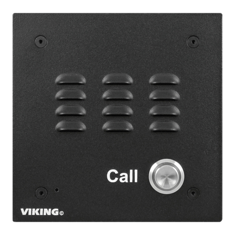
  9. Viking W-200 Instructions for use

Viking W-200 Instructions for use

Other Viking Intercom System manuals

Viking C-1000B Instructions for use

Viking

Viking C-1000B Instructions for use

Viking C-2000A Instructions for use

Viking

Viking C-2000A Instructions for use

Viking RC-2A Installation and operating instructions

Viking

Viking RC-2A Installation and operating instructions

Viking E-50-BK Instructions for use

Viking

Viking E-50-BK Instructions for use

Viking C-1000B User manual

Viking

Viking C-1000B User manual

Viking K-1200 Instructions for use

Viking

Viking K-1200 Instructions for use

Viking AES-2005 Instructions for use

Viking

Viking AES-2005 Instructions for use

Viking E-35-EWP User manual

Viking

Viking E-35-EWP User manual

Viking W-3005/EWP User manual

Viking

Viking W-3005/EWP User manual

Viking K-1700-3 Instructions for use

Viking

Viking K-1700-3 Instructions for use

Viking K-1770-IP Series User manual

Viking

Viking K-1770-IP Series User manual

Viking K-1775-IP Series User manual

Viking

Viking K-1775-IP Series User manual

Viking C-2000A User manual

Viking

Viking C-2000A User manual

Viking E-10A User manual

Viking

Viking E-10A User manual

Viking K-1705-IP Series User manual

Viking

Viking K-1705-IP Series User manual

Viking E-75-SS Instructions for use

Viking

Viking E-75-SS Instructions for use

Viking K-1705-3 Instructions for use

Viking

Viking K-1705-3 Instructions for use

Viking K-1775-3 Series User manual

Viking

Viking K-1775-3 Series User manual

Viking AES--2000 Instructions for use

Viking

Viking AES--2000 Instructions for use

Viking HID-1 Instructions for use

Viking

Viking HID-1 Instructions for use

Viking X-205 Series User manual

Viking

Viking X-205 Series User manual

Viking K-1205-EWP User manual

Viking

Viking K-1205-EWP User manual

Viking W-1000 Instructions for use

Viking

Viking W-1000 Instructions for use

Viking E-70-SS Instructions for use

Viking

Viking E-70-SS Instructions for use

Popular Intercom System manuals by other brands

Videx VRDK1 (25H) Technical manual

Videx

Videx VRDK1 (25H) Technical manual

Auta COMPACT VISUALTECH manual

Auta

Auta COMPACT VISUALTECH manual

Aiphone LC-10S instructions

Aiphone

Aiphone LC-10S instructions

Aiphone PD-1 instructions

Aiphone

Aiphone PD-1 instructions

Aiphone JF-DVF-HID-I instructions

Aiphone

Aiphone JF-DVF-HID-I instructions

Comelit 4893M Technical manual

Comelit

Comelit 4893M Technical manual

MGL Avionics V16 manual

MGL Avionics

MGL Avionics V16 manual

SSS Siedle BVI 750-0 Installation & programming

SSS Siedle

SSS Siedle BVI 750-0 Installation & programming

urmet domus AIKO 1716/1 quick start guide

urmet domus

urmet domus AIKO 1716/1 quick start guide

urmet domus IPerVoice 1039 Installation

urmet domus

urmet domus IPerVoice 1039 Installation

Alpha Communications STR QwikBus TT33-2 Installation, programming, and  user's manual

Alpha Communications

Alpha Communications STR QwikBus TT33-2 Installation, programming, and user's manual

Monacor ICM-20H instruction manual

Monacor

Monacor ICM-20H instruction manual

Logenex A202CR Installation & programming

Logenex

Logenex A202CR Installation & programming

Quantum QR5 Installation and programming manual

Quantum

Quantum QR5 Installation and programming manual

EVGA XR1 quick guide

EVGA

EVGA XR1 quick guide

CyberData 011211 series Installation quick reference

CyberData

CyberData 011211 series Installation quick reference

Vidos duo M1021 user manual

Vidos

Vidos duo M1021 user manual

Savant DOR-SMS-00 Deployment guide

Savant

Savant DOR-SMS-00 Deployment guide

manuals.online logo
manuals.online logoBrands
  • About & Mission
  • Contact us
  • Privacy Policy
  • Terms and Conditions

Copyright 2025 Manuals.Online. All Rights Reserved.

W
W-200
-200
Door Communication
System
October 9, 2003
P
Ph
ho
on
ne
e.
..
..
.7
71
15
5.
.3
38
86
6.
.8
88
86
61
1
i
in
nf
fo
o@
@v
vi
ik
ki
in
ng
ge
el
le
ec
ct
tr
ro
on
ni
ic
cs
s.
.c
co
om
m
h
ht
tt
tp
p:
:/
//
/w
ww
ww
w.
.v
vi
ik
ki
in
ng
ge
el
le
ec
ct
tr
ro
on
ni
ic
cs
s.
.c
co
om
m
Power: 120V AC/12V DC, 500mA UL listed adapter provided
Talk Battery: 15V DC
Dimensions: Controller: 120mm x 70mm x 35mm (4.75” x
2.75” x 1.38”), Speaker Box: 140mm x 115mm x 38mm (5.5” x
4.5” x 1.5”)
Weight: .75 Kg (1.5 lbs.)
Environmental: Controller: 0°C to 32°C (32°F to 90°F) with 5%
to 95% non-condensing humidity, Speaker Box: -26°C to 54°C (-
15°F to 130°F)
Connections: 6 wire modular cord (included)
Maximum Run: 500 feet to speaker box (24 gauge twisted)
Talk to Visitors at Your Door...
Even if You’re on the Phone!
P
Pr
ra
ac
ct
ti
ic
ce
e
T
TE
EL
LE
EC
CO
OM
MS
SO
OL
LU
UT
TI
IO
ON
NS
SF
FO
OR
RT
TH
HE
E2
21
1S
ST
TC
CE
EN
NT
TU
UR
RY
Y
TECHNICAL
TECHNICAL
S
Sp
pe
ec
ci
if
fi
ic
ca
at
ti
io
on
ns
s
F
Fe
ea
at
tu
ur
re
es
s• Communicate handsfree with doors or gates
• Commercial, industrial and residential
security applications
• Provide communication with delivery and
employee entrances
• Works in combination with existing doorbell
• Integrates easily with residential and busi-
ness phone systems
• “Hold” feature allows communication with the
speaker box while a phone call is in progress
• Microphone volume adjustment for back-
ground noise
• Electronics mount indoors
• Provides 15 volt talk battery
• Only two wires required to speaker box
phones. In addition, the W-
200 can also be configured to
work with business telephone
systems.
If the door bell sounds, even
when you are on the phone,
A
Ap
pp
pl
li
ic
ca
at
ti
io
on
ns
s
When used in combination with an existing doorbell, the
W-200 provides safe and reliable handsfree two way
communication through your existing residential
enter a Touch Tone command to communicate with the visitor at the door. Calls may be
disconnected or placed on “hold” and reconnected after the conversation with the
speaker box.
M
Ma
ad
de
ei
in
nt
th
he
eU
U.
.S
S.
.A
A.
.
A. Accessing Dial Tone
To gain access to C.O. dial tone, dial a Touch Tone “9”, then follow the oper-
ating examples below. When using private dial tone, remove JP1 shunt (see
diagram to the right). Note: Disconnect power and modular cord prior to
removing the cover of the W-200. Phones will instantly have dial tone for mak-
ing calls. Follow the Operating Examples, in the table below, for speaker box
access.
Due to the dynamic nature of the product design, the information contained in this document is subject to change without notice. Viking Electronics, and its affiliates and/or
subsidiaries assume no responsibility for errors and omissions contained in this information. Revisions of this document or new editions of it may be issued to incorporate
such changes.
Fax Back Doc 167
ZF301270 Rev C
Printed in the U.S.A.
P
Pr
ro
od
du
uc
ct
tS
Su
up
pp
po
or
rt
tL
Li
in
ne
e.
..
..
.7
71
15
5.
.3
38
86
6.
.8
86
66
66
6F
Fa
ax
xB
Ba
ac
ck
kL
Li
in
ne
e.
..
..
.7
71
15
5.
.3
38
86
6.
.4
43
34
45
5
I
In
ns
st
ta
al
ll
la
at
ti
io
on
n
B. Microphone Volume
In certain noisy locations the microphone sensitivity may
need to be decreased. A pot is provided on the bottom of
the W-200 to increase (clockwise) or decrease (counter-
clockwise) the microphone sensitivity. Note: The POT
comes factory set to the middle position.
A. Wiring the W-200
B. Mounting the W-200
P
Pr
ro
og
gr
ra
am
mm
mi
in
ng
g
VIKING©
W-200
DOORCOM
SYSTEM
BUSY
UP
VIKING©
Note: The W-200 may also be used without a
dial tone source. Jumper JP1 must be left in
place. When the doorbell sounds, access line
2 of a two-line phone, pick up a dedicated
telephone or access that line on a KSU/PABX
phone system. Touch Tone commands are
not needed to communicate with a doorbox.
Speaker Box
(included)
W-200 120V AC
Adapter
(included)
PABX/KSU 2-Line
Phone
House
Phone(s)
Dial
Tone
Telephone Jack
Assembly
(not included)
Operating Examples
To access the speaker box (disconnects the call in progress)
To place the call on hold and the speaker box
To return a call placed on hold
Enter Digits
✱9or #9
✱0or #0
✱or #
JP1
Internal View of the W-200
MIC
MIC
Increase
Decrease
Bottom View of the W-200
Red
Green
Blue
White
Black Yellow
Back panel of the Speaker Box
-
Q170200
100½0.5W
UP
VIKING©
To open the speaker box, remove
the two screws from the cover.
Mount back panel to a wall, a sin-
gle gang box or a 4”x4” junction
box with the arrow pointing up.
3.40”
1.55”
3.30”
2.35”
3.40”
Attach the cover to the base
with the two included screws
as shown.
Side view of the Speaker Box
Front view of the Speaker Box