manuals.online logo
Brands
  1. Home
  2. •
  3. Brands
  4. •
  5. Viking
  6. •
  7. Intercom System
  8. •
  9. Viking MSB-30/EWP User manual

Viking MSB-30/EWP User manual

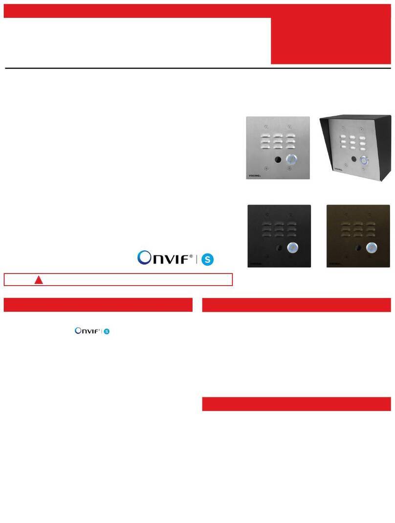
PRODUCT MANUAL
Designed, Manufactured and Supported in the USA
COMMUNICATION & SECURITY SOLUTIONS
Add Two-Way Voice Communication
to Your Existing IP Network Camera
Features
It is common for IP based network cameras to have two-
way audio connections. When this is the case, the MSB-
30 can be added to turn your IP network camera into a
VoIP (Voice over Internet Protocol) video phone, allowing
both voice and video to stream over the internet. If the
camera already has a tiny speaker and microphone, the
MSB-30 can be added to get better and louder sounding
audio by using the audio input and output connections
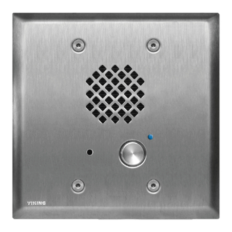
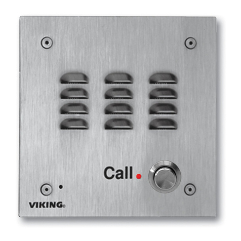
provided by the camera. The MSB-30 has a microphone,
a speaker, and a momentary push button housed in a
stainless steel flush mount panel. An optional Viking
model VE-5x5 can be used to surface mount the unit to a
wall or pedestal.
The MSB-30 line level audio input and output connections
can be directly connected to the IP camera’s line level
audio output and input connections for two-way voice
communications. A built-in 2 watt amplifier powers the in-
ternal speaker, and there are volume controls to adjust
both the speaker volume and microphone sensitivity. The
2 watt amplifier can be used to power an auxiliary speaker
for even greater volume and coverage.
The MSB-30 also has a momentary “CALL” button switch
which can provide a momentary contact closure to trigger
the IP network camera, or ring a door bell. The front panel
blue LED lights continuously to show the unit is powered,
and to help identify the “CALL” button location at night. An
external contact closure can be used to turn off the blue
LED, or simply wire it in parallel with the momentary “Call”
button switch to make the blue LED wink off when the but-
ton is pressed.
The MSB-30-EWP adds Enhanced Weather Protection
(EWP). Use for outdoor installations where the unit is ex-
posed to precipitation or condensation. EWP products fea-
ture foam rubber gaskets and boots, sealed connections,
gel-filled butt connectors, as well as urethane or thermal
plastic potted circuit boards with internally sealed, field-
adjustable trim pots. For more info, see DOD# 859.
• Vandal Resistant Features: 14 gauge louvered 316
stainless steel faceplate with permanent laser etched
graphics, speaker/mic screen, heavy duty metal “Call”
button and hex drive mounting screws
• Weather Resistant Features: Marine grade 316
stainless steel faceplate, screws and push button
switch. Switch internally sealed per IP67. Mylar
speaker. Self-draining mic mount. Faceplate, mic and
speaker gaskets. Weather resistant powder paint on
optional VE-5x5 (DOD# 424).
• Volume adjustments for microphone and speaker
• Two watt amplifier to drive speaker
• Power supply included
• Blue LED indicator
• Extended temperature range (-15°F to 130°F)
• Optional VE-5x5 surface mount back box (DOD# 424)
• Optional MSB-30-EWP is designed to meet IP66
Ingress Protection Rating (see DOD# 859 for more in-
formation)
Use with IP camera to add video and two-way voice
communications for:
• Business entrances
• Residential entrances
• Pedestrian gates
• ATM machines
• Parking lots/ramps
Power: 120V AC/13.8V AC UL listed adapter provided
Dimensions: Overall: 127mm x 127mm x 57mm (5” x 5”
x 2.25”), Plastic Electrical Box: 102mm x 102mm x 54mm
(4” x 4” x 2.12”)
Shipping Weight: 1.5 Kg (3.3 lbs)
Operating Temperature: -26°C to 54°C (-15°F to 130°F)
Humidity – MSB-30: 5% to 95% non-condensing
Humidity – MSB-30-EWP: Up to 100% condensing
Connections: Gel-filled butt connectors
MSB-30/EWP
Mic/Speaker/Button
Panel for IP Cameras
April 3, 2014
Applications
Specifications
www.vikingelectronics.com
Information: (715) 386-8861
VIKING
Features Overview
Installation
Call
VIKING©
Push Button Switch: Solid 316 stainless
steel internally sealed per IP67.
Speaker Screen: Stainless steel speaker
screen with 0.018" diameter holes to
prevent punctures from paperclips, etc.
Faceplate: 14 gauge Marine grade 316
stainless steel faceplate and push button
switch (sealed per IP67). Speaker: Mylar speaker with rubber gasket
to maintain water-tight seal and eliminate
water deterioration.
Condensation Drain Hole
Mounting Screws: (4) 6-32 x 3/4" Marine
grade 316 stainless steel, flat head, 5/64"
hexdrive, screws (included).
LED: Lights blue when powered up.
Faceplate Gasket: 1/8" thick closed cell
PVC to provide a water-tight seal.
Microphone: Omni-directional microphone
with protective water-resistant cloth.
Microphone Volume
Speaker Volume
Line Level Audio Output from Microphone (YELLOW wires)
Push Button Contacts (BLACK wires)
LED Control Input (BLUE wires)
12-15V AC or DC Power Input (RED/BLACK wires)
Line Level Audio Input (ORANGE wires)
Auxiliary Speaker Output (WHITE wires)
Ring Terminal
(included)
Earth
Ground
(optional)
To increase surge protection,
loosen the PCB mounting
screw and fasten a wire with
the included ring terminal from
the mounting screw to earth
ground (grounding rod, water
pipe, etc.)
Front View of Optional
VE-5x5 (not included)
2.25”
Condensation
Drain Hole
*Adhere gasket to front
panel, centering over
mounting holes
5.14”
5.22” 3.25”
Call
4.0"
Rear View of VE-5x5
(not included)
Push to Call Button
Blue LED Power Indicator
(4) 6-32 X 3/4” stainless steel, flat
head, hexdrive, screws (included)
Condensation Drain Hole
5.0”
MSB-30-EWP shown with Viking
model VE-GNP Gooseneck Pedestal
(4) 0.38” diameter
(for gooseneck mounting)
(4) 0.2 x 0.43 slots
for double gang box
(2) 0.2 x 0.43 slots
for single gang box
(1) 0.74" dia 3.0” 3.3”
3.0”
2.1”
Wall Stud
Front View of
Plastic Rough-In
Box (included)
Wire knock out
(2) Standard flat head dry wall
(sheet rock) screws (not included)
IMPORTANT: Electronic devices are susceptible to lightning and power station electrical surges from both the AC
outlet and the telephone line. It is recommended that a surge protector be installed to protect against such surges.
2
A. Mounting
The optional VE-5x5 Surface
Mount Box is designed to be surface mounted
to a single gang box, double gang box or VE-
GNP gooseneck pedestal (right). For more in-
formation on the VE-5x5 and VE-GNP see
DOD# 424.
Important: The MSB-30 will NOT
mount to a standard double gang box.
Caution: When warm air comes in contact with cold surfaces, such as outside walls and conduits, it causes con-
densation. To prevent condensation from accumulating inside the MSB-30 always bring conduit into the bottom
of the unit. If this is not possible, drill a 1/4” diameter hole in the bottom of the black plastic box.
*Note: Peel off paper liner and adhere gasket to the back of the faceplate, centering it over the four corner mount-
ing holes.
Note: The plastic rough-in box (part # 259576) may be purchased
separately in advance. Go to www.vikingelectronics.com and
click on “Spare Parts”.
3
ORANGE
ORANGE
IP Network Camera
with Two-Way Audio
(not included) Rear View of MSB-30
Audio
In
Audio
Out
Audio In
Push Button Contacts
Trigger
Input
Door Bell
Circuit
OR
Model 25AE
Paging Horn
(not included)
Model 35AE
Ceiling Speaker
(not included)
Model 30AE
Ceiling Speaker
(not included)
LED Control Input
Mic Audio Out
YELLOW
YELLOW
BLACK
BLACK
BLUE
BLUE
OR
13.8V AC 1.25A
Adapter (included)
RED WITH BLACK STRIPE
BLACK WITH RED STRIPE
Auxiliary Speaker Output
WHITE
WHITE
* Gel-filled Butt
Connectors (included)
Microphone Volume
Speaker Volume
B. Wiring
* Note: The gel-filled (water-tight) butt connectors are designed
for insulation displacement on 19-26 gauge wire with a maximum
insulation of 0.082 inches. Do not strip wires prior to terminating.
Each of the MSB-30’s features can be used a’ la carte. So depending on your application, connect only the features
that are needed.
1. If microphone audio is needed, connect the MIC AUDIO OUT (yellow wires) to the camera’s Line Level Audio
In connections.
2. If arrival notification is needed, connect the PUSH BUTTON (black wires) to a trigger or alarm input, or use in
place of an existing doorbell.
3. If controlling the front panel blue LED light is needed, connect the LED CONTROL (blue wires) to a normally
open set of contacts. The blue LED will go dark when the contacts are closed. The LED CONTROL can also be
connected directly to the PUSH BUTTON (black wires) to make the blue LED wink off when the “CALL” button is
pressed.
If the camera has a motion sensing feature that is used for detecting the arrival of a person, connect the PUSH
BUTTON (black wires) to the LED CONTROL (blue wires) to give appearance the “CALL” button is functional
when pressed.
4. If additional speaker volume is needed, connect the AUX SPEAKER (white wires) to up to three 8 ohm speakers.
5. If speaker audio is needed, connect the AUDIO IN (orange wires) to the camera’s Line Level Audio Output.
6. When all else is wired, connect the 12-15V AC OR DC (red/black wires) to the provided power supply adapter.
Printed in the U.S.A.
4
Operation
Each of the MSB-30 features operates independently, so any or all of them can be use or not used. Listed below is
how each of the features operates.
1. MIC AUDIO OUT is a line level audio output of the audio picked up by the MSB-30’s internal microphone. The
output level (or sensitivity of the microphone), can be adjusted with the volume control labeled “MIC”.
2. AUDIO IN is a line level input that is amplified with an on-board 2 watt amplifier to drive the MSB-30’s internal
speaker. The speaker volume can be adjusted with the volume control labeled “SPEAKER”.
3. AUX SPEAKER is an additional speaker output, driven from the same 2 watt internal amplifier, that can drive up to
an additional three 8 ohm speakers. Viking models 30AE and 35AE ceiling speakers can be used for indoor applica-
tions, and the Viking model 25AE paging horn can be used for outdoor, factory, or warehouse environments.
4. PUSH BUTTON is a normally open set of contacts that momentarily close when the front paneled “Call” button is
pressed.
5. LED CONTROL is a normally open input that will turn off the front panel blue LED light when a contact closure is
provided.
6. 12 – 15V AC OR DC is the power supply input. The MSB-30 comes with an included 13.8VAC power adapter.
IF YOU HAVE A PROBLEM WITH A VIKING PRODUCT, CONTACT: VIKING TECHNICAL SUPPORT AT (715) 386-8666
Our Technical Support Department is available for assistance Monday 8am - 4pm and Tuesday through Friday 8am - 5pm central time. So that we can give you better service, before you call please:
1. Know the model number, the serial number and what software version you have (see serial label).
2. Have your Product Manual in front of you.
3. It is best if you are on site.
RETURNING PRODUCT FOR REPAIR
The following procedure is for equipment that needs repair:
1. Customer must contact Viking's Technical Support Department at 715-386-8666 to obtain a Return Authorization (RA) number. The customer MUST have a complete description of the problem,
with all pertinent information regarding the defect, such as options set, conditions, symptoms, methods to duplicate problem, frequency of failure, etc.
2. Packing: Return equipment in original box or in proper packing so that damage will not occur while in transit. Static sensitive equipment such as a circuit board should be in an anti-static bag,
sandwiched between foam and individually boxed. All equipment should be wrapped to avoid packing material lodging in or sticking to the equipment. Include ALL parts of the equipment. C.O.D. or
freight collect shipments cannot be accepted. Ship cartons prepaid to: Viking Electronics, 1531 Industrial Street, Hudson, WI 54016
3. Return shipping address: Be sure to include your return shipping address inside the box. We cannot ship to a PO Box.
4. RA number on carton: In large printing, write the R.A. number on the outside of each carton being returned.
RETURNING PRODUCT FOR EXCHANGE
The following procedure is for equipment that has failed out-of-box (within 10 days of purchase):
1. Customer must contact Viking’s Technical Support at 715-386-8666 to determine possible causes for the problem. The customer MUST be able to step through recommended tests for diagnosis.
2. If the Technical Support Product Specialist determines that the equipment is defective based on the customer's input and troubleshooting, a Return Authorization (R.A.) number will be issued.
This number is valid for fourteen (14) calendar days from the date of issue.
3. After obtaining the R.A. number, return the approved equipment to your distributor, referencing the R.A. number. Your distributor will then replace the Viking product using the same R.A. number.
4. The distributor will NOT exchange this product without first obtaining the R.A. number from you. If you haven't followed the steps listed in 1, 2 and 3, be aware that you will have to
pay a restocking charge.
Warranty
DOD# 213
Due to the dynamic nature of the product design, the information contained in this document is subject to change without notice. Viking Electronics, and its affiliates
and/or subsidiaries assume no responsibility for errors and omissions contained in this information. Revisions of this document or new editions of it may be issued
to incorporate such changes.
Product Support: (715) 386-8666
ZF303250 Rev A
TWO YEAR LIMITED WARRANTY
Viking warrants its products to be free from defects in the workmanship or materials, under normal use and service, for a period of two years from the date of purchase
from any authorized Viking distributor. If at any time during the warranty period, the product is deemed defective or malfunctions, return the product to Viking Electronics,
Inc., 1531 Industrial Street, Hudson, WI., 54016. Customer must contact Viking's Technical Support Department at 715-386-8666 to obtain a Return Authorization (R.A.)
number.
This warranty does not cover any damage to the product due to lightning, over voltage, under voltage, accident, misuse, abuse, negligence or any damage caused by
use of the product by the purchaser or others. This warranty does not cover non-EWP products that have been exposed to wet or corrosive environments. This warranty
does not cover stainless steel surfaces that have not been properly maintained.
NO OTHER WARRANTIES. VIKING MAKES NO WARRANTIES RELATING TO ITS PRODUCTS OTHER THAN AS DESCRIBED ABOVE AND DISCLAIMS ANY EX-
PRESS OR IMPLIED WARRANTIES OR MERCHANTABILITY OR FITNESS FOR ANY PARTICULAR PURPOSE.
EXCLUSION OF CONSEQUENTIAL DAMAGES. VIKING SHALL NOT, UNDER ANY CIRCUMSTANCES, BE LIABLE TO PURCHASER, OR ANY OTHER PARTY,
FOR CONSEQUENTIAL, INCIDENTAL, SPECIAL OR EXEMPLARY DAMAGES ARISING OUT OF OR RELATED TO THE SALE OR USE OF THE PRODUCT SOLD
HEREUNDER.
EXCLUSIVE REMEDY AND LIMITATION OF LIABILITY. WHETHER IN AN ACTION BASED ON CONTRACT, TORT (INCLUDING NEGLIGENCE OR STRICT LIABILITY)
OR ANY OTHER LEGAL THEORY, ANY LIABILITY OF VIKING SHALL BE LIMITED TO REPAIR OR REPLACEMENT OF THE PRODUCT, OR AT VIKING'S OPTION,
REFUND OF THE PURCHASE PRICE AS THE EXCLUSIVE REMEDY AND ANY LIABILITY OF VIKING SHALL BE SO LIMITED.
IT IS EXPRESSLY UNDERSTOOD AND AGREED THAT EACH AND EVERY PROVISION OF THIS AGREEMENT WHICH PROVIDES FOR DISCLAIMER OF WAR-
RANTIES, EXCLUSION OF CONSEQUENTIAL DAMAGES, AND EXCLUSIVE REMEDY AND LIMITATION OF LIABILITY, ARE SEVERABLE FROM ANY OTHER PRO-
VISION AND EACH PROVISION IS A SEPARABLE AND INDEPENDENT ELEMENT OF RISK ALLOCATION AND IS INTENDED TO BE ENFORCED AS SUCH.

Other Viking Intercom System manuals

Viking E-35-EWP User manual

Viking

Viking E-35-EWP User manual

Viking HID-1 Instructions for use

Viking

Viking HID-1 Instructions for use

Viking E-75-BN Instructions for use

Viking

Viking E-75-BN Instructions for use

Viking W-1000 Instructions for use

Viking

Viking W-1000 Instructions for use

Viking K-1775-3 Series User manual

Viking

Viking K-1775-3 Series User manual

Viking E-70-BK User manual

Viking

Viking E-70-BK User manual

Viking E-40-BN Instructions for use

Viking

Viking E-40-BN Instructions for use

Viking K-1205-EWP User manual

Viking

Viking K-1205-EWP User manual

Viking TBB-1 Instructions for use

Viking

Viking TBB-1 Instructions for use

Viking K-1205-EWP Instructions for use

Viking

Viking K-1205-EWP Instructions for use

Viking K-1700-IP-EWP User manual

Viking

Viking K-1700-IP-EWP User manual

Viking E-75 Series User manual

Viking

Viking E-75 Series User manual

Viking E-60-SS-IP User manual

Viking

Viking E-60-SS-IP User manual

Viking K-1700-3 Instructions for use

Viking

Viking K-1700-3 Instructions for use

Viking D10 Instructions for use

Viking

Viking D10 Instructions for use

Viking X-205 Series User manual

Viking

Viking X-205 Series User manual

Viking E-60-SS User manual

Viking

Viking E-60-SS User manual

Viking E-35-EWP User manual

Viking

Viking E-35-EWP User manual

Viking X-35-SS-EWP User manual

Viking

Viking X-35-SS-EWP User manual

Viking E-60-BK Instructions for use

Viking

Viking E-60-BK Instructions for use

Viking K-1205-IP Series User manual

Viking

Viking K-1205-IP Series User manual

Viking E-60 Series Instructions for use

Viking

Viking E-60 Series Instructions for use

Viking AES--2000 Instructions for use

Viking

Viking AES--2000 Instructions for use

Viking AES--2000 Instructions for use

Viking

Viking AES--2000 Instructions for use

Popular Intercom System manuals by other brands

EGi Millennium 1201 user manual

EGi

EGi Millennium 1201 user manual

Alpha Communications ART4LITE/G2 Installation

Alpha Communications

Alpha Communications ART4LITE/G2 Installation

TCS ISW3130 Product information

TCS

TCS ISW3130 Product information

Vimar Elvox 6621 operating instructions

Vimar

Vimar Elvox 6621 operating instructions

Vimar ELVOX TAB 7 IP user manual

Vimar

Vimar ELVOX TAB 7 IP user manual

SSS Siedle BFSV 850-0 operating instructions

SSS Siedle

SSS Siedle BFSV 850-0 operating instructions

Vega QX-6A owner's manual

Vega

Vega QX-6A owner's manual

Algo 8039 Installation/configuration

Algo

Algo 8039 Installation/configuration

Forematic 502 Safety & Operating Instructions

Forematic

Forematic 502 Safety & Operating Instructions

Connexus LBB7026 Series user guide

Connexus

Connexus LBB7026 Series user guide

Midland BTX1 PRO S Instruction guide

Midland

Midland BTX1 PRO S Instruction guide

CAME BPT LVKIT installation manual

CAME BPT

CAME BPT LVKIT installation manual

Vimar ELVOX 7558/E Installation and operation manual

Vimar

Vimar ELVOX 7558/E Installation and operation manual

Farfisa Zhero ZH1151WE manual

Farfisa

Farfisa Zhero ZH1151WE manual

Akuvox R27A user manual

Akuvox

Akuvox R27A user manual

Elvox GIOTTO 6302/A Installation and operation manual

Elvox

Elvox GIOTTO 6302/A Installation and operation manual

Somogyi home DP 012 instruction manual

Somogyi

Somogyi home DP 012 instruction manual

Comelit Bravo Series Technical sheet

Comelit

Comelit Bravo Series Technical sheet

manuals.online logo
manuals.online logoBrands
  • About & Mission
  • Contact us
  • Privacy Policy
  • Terms and Conditions

Copyright 2025 Manuals.Online. All Rights Reserved.