Viking F20513A User manual

Viking Range Corporation
111 Front Street
Greenwood, Mississippi 38930 USA
(662) 455-1200
For produ t information,
all 1-888-VIKING1 (845-4641)
or visit the Viking Web site at
vikingrange. om
F20513A EN (070208J)
®
Viking Installation Guide
Professional Freestanding 30”Gas
and Gas Self-Clean Sealed Burner Range

IMPORTANT–Read and Follow!
3
2
Table of Contents
• Before beginning, please read these
instru tions ompletely and arefully.
• Do not remove permanently affixed labels,
warnings, or plates from produ t. This may
void the warranty.
• All lo al and national odes and ordinan es
must be observed. Installation must
onform with lo al odes or in the absen e
of odes, the National Fuel Gas Code ANSI
Z223.1 INFPA54.
• The installer must leave these instru tions
with the onsumer who should retain for
lo al inspe tor’s use and for future
referen e.
In Canada: Installation must be in a ordan e
with the urrent CAN/CGA B149.1 & 2 Gas
Installation odes and/or lo al odes. Ele tri al
installation must be in a ordan e with the
urrent CSA C22.1 Canadian Ele tri al Codes
Part 1 and/or lo al odes.
In Massachusetts: All gas produ ts must be
installed by a “Massa husetts” li ensed
plumber or gasfitter. A “T” type handle
manual valve must be installed in the gas
supply line to the applian e.
Your safety and the safety of others is
very important.
We h ve provided m ny import nt s fety
mess ges in this m nu l nd on your
ppli nce. Alw ys re d nd obey ll
s fety mess ges.
This is the s fety lert symbol. This
symbol lerts you to h z rds th t
c n kill or hurt you nd others.
All s fety mess ges will be preceded by
the s fety lert symbol nd the word
“DANGER,” “WARNING” or “CAUTION.”
These words me n:
Hazards or unsafe pra ti es
whi h WILL result in severe personal
injury or death
DANGER
Hazards or unsafe pra ti es
whi h COULD result in severe personal
injury or death
Hazards or unsafe pra ti es whi h
COULD result in minor personal injury or
property damage.
All s fety mess ges will identify the
h z rd, tell you how to reduce the ch nce
of injury, nd tell you wh t c n h ppen if
the instructions re not followed.
WARNING
CAUTION
Warnings & Important Safety Instru tions _______________________________________________3
Dimensions _________________________________________________________________________6
Spe ifi ations _______________________________________________________________________7
Clearan e Dimensions (Proximity to Cabinets)___________________________________________8
Clearan e Dimensions (Wood/Composite Overlay) ______________________________________9
Ele tri al & Gas Requirements _______________________________________________________10
General Information ________________________________________________________________12
Installation_________________________________________________________________________13
Door Removal __________________________________________________________________13
Leg Installation _________________________________________________________________14
Leveling/Adjustments/Alignment _________________________________________________15
Anti-tip Devi e Installation _______________________________________________________16
Conne ting Gas & Ele tri _______________________________________________________17
Standoff Bra ket Removal________________________________________________________18
Final Installation ________________________________________________________________18
Door Repla ement and Adjustment _______________________________________________19
Final Preparation ___________________________________________________________________20
Performan e Che klist ______________________________________________________________20
Servi e & Registration_______________________________________________________________21

IMPORTANT–Read and Follow!
5
4
DANGER
GAS LEAK HAZARD
To void risk of person l injury
or de th; le k testing of the
ppli nce must be conducted
ccording to the m nuf cturer’s
instructions. Before pl cing ppli nce in
oper tion, lw ys check for g s le ks
with so py w ter solution.
• DO NOT USE AN OPEN FLAME TO
CHECK FOR GAS LEAKS.
DANGER
ELECTRICAL SHOCK
HAZARD
To void risk of electric l shock,
person l injury or de th; verify
your ppli nce h s been properly
grounded in ccord nce with loc l codes
or in bsence of codes, with the N tion l
Electric l Code (NEC). ANSI/NFPA 70-
l test edition.
WARNING
MOVING HAZARD
To void risk of severe
person l injury; this ppli nce
requires two or more personnel
while h ndling nd moving. Possible
use of ppli nce moving devices is
recommended.
DANGER
Fire/explosion hazard.
IF THE INFORMATION IN
THIS MANUAL IS NOT
FOLLOWED EXACTLY, A
FIRE OR EXPLOSION MAY RESULT
CAUSING PROPERTY DAMAGE,
PERSONAL INJURY, OR DEATH.
•DO NOT store or use g soline or other
fl mm ble v pors nd liquids in the
vicinity of this or ny other ppli nce.
•WHAT TO DO IF YOU SMELL GAS:
–DO NOT try to light ny ppli nce.
–DO NOT touch ny electric l switch;
DO NOT use ny phone in your
building.
–Immedi tely c ll your g s supplier from
neighbor’s phone.
–Follow the g s supplier’s instructions.
–If you c nnot re ch your g s supplier,
c ll the fire dep rtment.
• Inst ll tion nd service must be
performed by qu lified inst ller, service
gency, or the g s supplier.
DANGER
CHEMICAL HAZARD
To void risk of property
d m ge nd/or person l injury
or de th; this ppli nce is not
too be used s he ting source.
• Benzene is chemic l which is p rt of
the g s supply to this cooking product,
which is consumed in the fl mes during
combustion. Exposure to sm ll
mount of benzene is possible if g s
le k occurs. Form ldehyde nd soot re
by-products of incomplete combustion.
• This ppli nce cont ins or produces
chemic ls which c n c use serious
injury or de th nd which re known to
the st te of C liforni to c use c ncer,
birth defects or other reproductive h rm.
To reduce the risk from subst nces in
the fuel or from fuel combustion m ke
sure this ppli nce is inst lled,
oper ted, nd m int ined in ccord nce
to the instructions in this document.
WARNING
TIPPING HAZARD
To reduce the risk of property
d m ge or person l injury;
inst ll nti-tipping device
provided in ccord nce with
the inst ll tion instructions in
this document. Device must be
eng ged properly to prevent
product from tipping over.
• This r nge c n tip.
• Injuries to persons c n result.
• Inst ll nti-tip device p cked with r nge.
• See inst ll tion instructions.

Spe ifi ations
7
Dimensions
6
Gas 30” Ran e Gas 30” Range
Description
VGCC530-4B/VGSC530-4B
Overall width 29-7/8” (75.9 m)
Overall height To top of side trim
35-7/8” (91.1 m) min.
37” (94 m) max.
Legs adjust 1-1/8” (2.9 m)
Overall depth from
rear*
To end of side panel—24-5/16” (61.8 m)
To front of door—25-3/4” (65.4 m)
To end of landing edge—28-1/16” (72.2 m)
To end of door handle—28-11/16” (72.9 m)
*Add 3/8” (1 m) to overall depth for VGSC models installed against a ombustible wall.
Additions to Base
Height
To top of island trim—add 1” (2.5 m)
To top of ba kguard—add 8” (20.3 m)
To top of high-shelf—add 23-1/2” (59.7 m)
Gas requirements Shipped natural or LP/Propane gas; field onvertible with onversion kit
(pur hased separately); a epts standard residential 1/2” (1.3 m) ID gas servi e line.
Gas manifold
pressure Natural 5.0” W.C.P. / Liquid propane L/P 10.0” W.C.P.
Ele tri al
requirements
120VAC/60 Hz; 4 ft. (121.9 m), 3-wire ord with grounded
3-prong plug atta hed to unit
Maximum amp usage .83 amps
Surfa e burner rating
Natural gas
LP
15,000 BTU (4.4 kW)
12,500 BTU (3.7 kW)
Griddle burner rating N/A
Grill burner rating N/A
Oven interior width 23” (58.4 m)
Oven interior height 16-1/8” (41.0 m)
Oven interior depth Overall—18-3/4” (47.6 m)
AHAM—VGCC530 17” (43.1 m)
AHAM—VGSC530 15-3/8” (39.0 m)
Oven volume Total oven apa ity—4.0 u. ft.
Measured to AHAM standards—VGCC530 3.7 u. ft.
Measured to AHAM standards—VGSC530 3.3 u. ft.
Approximate
shipping weight 410 lbs. (184.5 kg)
29-7/8”
(75.9cm)
35-7/8”
(91.1cm)min.
to
37”
(94cm)max.
8”
(20.3cm)
Minimum learan es from adja ent ombustible onstru tion:
Below ooking surfa e (36” [91.4 m] and below)
• Sides - 0”
• Top grate support - 36” (91.4 m)
Above ooking surfa e (above 36” [91.4 m])
• Sides - 6” (15.2 m)
• Within 6” (15.2 m) side learan e, wall abinets no deeper than 13” (33.0 m) must be minimum 18” (45.7 m)
above ooking surfa e
• Wall abinets dire tly above produ t must be a minimum of 42” (106.7 m) above ooking surfa e
• Rear - 0” with 8” ba kguard or high shelf; 0” with island trim and non- ombustible rear wall;
• 6” (15.2 m) with island trim and ombustible rear wall
Note: Unit shown with standard 8” (20.3 cm) backguard.
Note: VGSC self-clean ranges are 3/8” deeper than VGCC non self-clean ranges.
*A 3/8” (1 m) standoff is in luded on ea h VGSC model range and is required for installation against
a ombustible wall. These 3/8” (1 m) bra kets (4) an easily be removed if installing against a non-
ombustible wall.
8-1/8”
(20.6 cm)
1-5/8”
(4.1 cm)
8”
(20.3 cm)
35-7/8”
(91.1 cm) min.
to
37”
(94 cm) max.
19-3/8”
(49.2 cm)
26-1/8” (66.4 cm)
28-1/16” (72.2cm)
26-7/16” (67.2 cm)
24-5/16” (61.8 cm)
45-1/2” (116.0 cm)
3/8”
(1 cm)
*

42”min.
(106.7cm)
13”max.
(
33.0cm)
6”min.
(15.2cm)
18”min.
(45.7cm)
3/8”
(0.95cm)
36”
(91.4cm)
29-7/8”
(75.9cm)
Clearan e Dimensions (Wood/Composite Overlay)
9
Clearan e Dimensions (Proximity to Cabinets)
8
• This range may be installed dire tly
adja ent to existing 36” (91.4 m) high
base abinets.
IMPORTANT: The side trim MUST be
3/8” (.95 m) above the adja ent base
abinet ountertop. This an be
a omplished by raising the unit using
the adjustment spindles on the legs.
• The range CANNOT be installed
dire tly adja ent to sidewalls, tall
abinets, tall applian es, or other
side verti al surfa es above 36”
(91.4 m) high. There must be a
minimum of 6” (15.2 m) side
learan e from the range to su h
ombustible surfa es above the
36” (91.4 m) ounter height.
• Within the 6” (15.2 m) side
learan e to ombustible verti al
surfa es above 36” (91.4 m), the
maximum wall abinet depth
must be 13” (33.0 m) and wall
abinets within this 6” (15.2 m)
side learan e must be 18”
(45.7 m) above the 36”
(91.4 m) high ountertop.
• Wall abinets above the range must be a
minimum of 42” (106.7 m) above the
range ooking surfa e for the full width
of the range. This minimum height
requirement does not apply if a range
hood is installed over the ooking surfa e.
The bottom of a standard hood should be
30” (76.2 m) min. to 36” (91.4 m) max.
above the ountertop. This would typi ally
result in the bottom of the hood being
66” (167.6 m) to 72” (182.9 m) above the
floor. Refer to the range hood installation
instru tions for additional information.
These dimensions provide for safe and
effi ient operation of the hood.
66”min.
(167.6cm)
to
72”max.
(182.9cm)
66”min.
(167.6cm)
to
72”max.
(182.9cm)
24”
(61.0cm)
or
27”
(38.6cm)
30”
(76.2cm)
6”
(15.2cm)
Wood/Composite
Overlay
Wood/Composite
Overlay
30”min.
(76.2cm)
to
36”max.
(91.4cm)
0”
(
0cm)
30”min.
(76.2cm)
to
36”max.
(91.4cm)
Wall Installation
Island Installation
Note: Minimum clearance for back wall is 0” with
backguard or high-shelf.
Note: If a range hood is installed, wall cabinets
above the range have a different minimum
clearance height.
Note: 6” ( 5.2 cm) min. with island trim and
combustible rear wall. 0” with island trim and
non-combustible rear wall. See Standoff
Bracket Removal section to allow 0” clearance.
Note: Minimum clearance for back wall
is 0” with backguard or high-shelf. See
Standoff Bracket Removal section to
allow 0” clearance.
CAUTION
Burn hazard
To void risk of person l injury;
the use of c binets for stor ge
bove the ppli nce m y result
in potenti l burn h z rd. Combustible
items m y ignite, met llic items m y
become hot nd c use burns. If c binet
stor ge is to be provided the risk c n be
reduced by inst lling r ngehood th t
projects horizont lly minimum 5”
(12.7 cm) beyond the bottom of c binets.

11
Ele tri al & Gas Requirements
10
Electrical Requirements
Che k your national and lo al odes
regarding this unit. This range requires
120VAC/60 Hz; 4 ft. (121.9 m), 3-wire ord
with grounded 3-prong plug atta hed to
unit. See “Ele tri al Conne tion” se tion for
grounding instru tions. Must be fused
seperately from any other ir uit.
Gas Connection
The gas supply (servi e) line must be the
same size or greater than the inlet line of the
applian e. This range uses a 1/2” (1.3 m) ID
NPT (S h40) inlet. Sealant on all pipe joints
must be resistive to LP gas.
The ran e is desi ned specifically for
natural as or liquid propane (LP) as.
Before be innin installation verify that
the model is compatible with the intended
as supply.
Manual shut-off valve:
This installer-supplied valve must be installed
in the gas servi e line before the applian e
in the gas stream and in a lo ation where it
an be rea hed qui kly in the event of
an emergen y. Any opeing behind the range
shall be sealed.
In Massachusetts: A “T” handle type
manual valve must be installed in the gas
supply line to the applian e.
IMPORTANT: Any conversion required
must be performed by your dealer or a
qualified licensed plumber or as service
company. Please provide the servi e person
with this manual before work begins.
Pressure Re ulator:
• All heavy-duty, ommer ial type ooking
equipment must have a pressure regulator
on the in oming servi e line for safe and
effi ient operation, sin e servi e pressure
may flu tuate with lo al demand. External
regulators are not required on this range
sin e a regulator is built into ea h unit at
the fa tory. Under no ondition bypass
this built-in regulator.
• Manifold pressure should be he ked with
a manometer, natural gas requires 5.0”
W.C.P. and LP gas requires 10.0” W.C.P.
In oming line pressure upstream from the
regulator must be 1” W.C.P. higher than
the manifold pressure in order to he k
the regulator. The regulator used on this
range an withstand a maximum input
pressure of 1/2” PSI (14.0” W.C.P.). If the
line pressure is in ex ess of that amount, a
step down regulator will be required.
• The applian e must be dis onne ted from
the gas supply piping system during any
pressure testing of that system.
2” dia.
(5.1 cm)
2-3/4”
(7.0 cm)
2-1/2”
(6.4 cm)
1-3/4”
(4.4 cm)
28-5/16”
(71.9 cm)
23-7/16”
(59.5 cm)
Gas or electrical
connection in
this area
Gas connection
in this area
4-3/8”
(11.1 cm)
31-1/16”
(78.9 cm)
WARNING
ELECTRICAL SHOCK
HAZARD
To void the risk of electric l
shock, person l injury or de th;
verify electric l power is turned off t the
bre ker box nd g s supply is turned off
until the r nge is inst lled nd re dy to
oper te, inst ll tion by n uthorized
inst ller only.
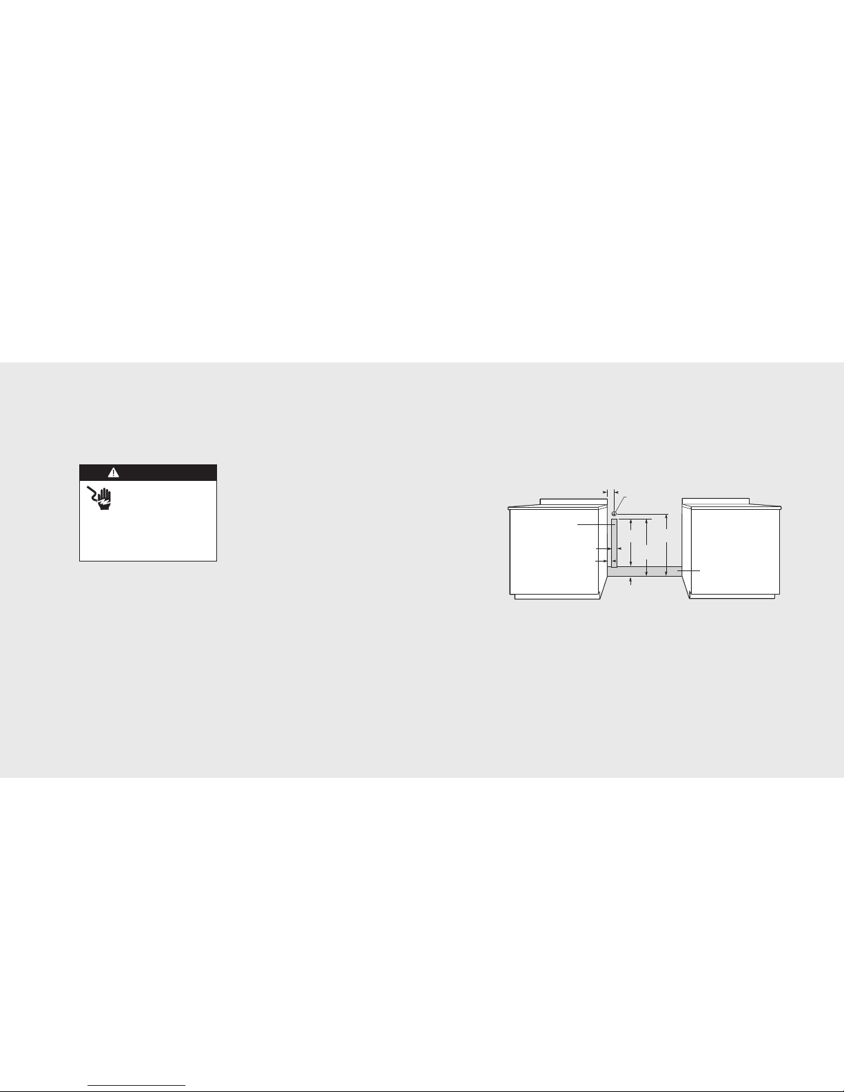
Flexible Connections:
If the unit is to be installed with flexible
ouplings and/or qui k-dis onne t fittings,
the installer must use a heavy-duty AGA
design- ertified flexible onne tor of at least
1/2” (1.3 m) ID NPT (with suitable strain
reliefs) in omplian e with ANSI Z21.41
and Z21.69.
In Canada: CAN 1-6, 10-88 metal
onne tors for gas applian es and CAN
1-6.9 M79 qui k dis onne t devi es for use
with gas fuel.
In Massachusetts: This applian e must be
installed with a 36” (3-foot) long flexible
gas onne tor.
Ele tri al & Gas Requirements

1312
General Information
READ AND FOLLOW ALL WARNING
AND CAUTION INFORMATION WHEN
INSTALLING THIS APPLIANCE.
• All openings in the wall behind the
applian e and in the floor under the
applian e must be sealed.
• Do not obstru t the flow of ombustion and
ventilation air.
Movin , Handlin , and Unpackin
Remove and dis ard all pa king materials,
in luding ardboard and tape on the outside
and inside of the range.
Remove the burner grates and styrofoam
off the top ooking surfa e. Be sure to
remove the burner aps pa kaged in
styrofoam below the burner grates.
Do not dis ard the anti-tip metal
bra ket supplied with the range.
This is the anti-tip devi e and must
be installed with the unit. Refer to
“Anti-tip Device Installation”
section.
Some stainless steel parts may have a plasti
prote tive wrap whi h must be peeled off.
The interior should be washed thoroughly
with hot, soapy water to remove film
residues and any dust or debris before being
used, then rinsed and wiped dry. Solutions
stronger than soap and water are rarely
needed.
NOTICE
DO NOT use the h ndle or oven door to
lift the oven. Remove door before
inst ll tion to ensure th t it is not used to
lift the unit. DO NOT lift or c rry the door
by the h ndle.
Removing the door must be done by your
de ler, qu lified licensed plumber, or
certified g s inst ller.
Door Removal
1
Open door ompletely. Pla e pins, supplied with unit, in
pin hole. For personal safety, ONLY use pins
supplied with the unit.
2
Remove hinge trim s rews. Take off hinge trim. Identify
right and left hinge for future re-installation.
3
Close until pins stop door.
4
Lift door up and out.
Installation

14 15
1
1
1
2
3
2
Legs are pa ked in styrofoam top pa k.
Note: Legs should be installed near to where
appliance is to be used, as they are
not secure for long transit.
Note: It is strongly recommended
that a pallet or lift jack be used rather than tilting.
Raise unit about a foot.
Unscrew temporary legs from
couplings on all four corners
.
4
Lower range gently to keep any undue strain from
legs and internal mounting hardware.
3
S rew legs into ouplings on all
four orners.
Leg Installation
1
2
Measure the four orners in utout area to verify if
flooring is level.
For uneven or sloped floors, level unit with metal shims
only, as the adjustment required may ex eed
the thread available in the leg.
3
4
3/8”
3/8”
(0.95cm)
(0.95 cm)
3/8”
(0.95cm)
Move unit into opening.
Leveling/Adjustments/Alignment
5
Che k that unit is level side to
side and front to ba k. Side trim of the high orner
must be 3/8” (0.95 m) above ountertop.
If leveling is required, move unit out of opening.
6
1
2
1
Lift unit and prop on wood blo ks.

1716
1
Measurement (A)
Measurement (A)Measurement (A)
2
Measurement(A)
Measurement (A)
+1/2”
+1/2” (1.3cm)
(1.3 cm)
Measurement(A)
+1/2” (1.3 cm)
3-5/8”
3-5/8”
(9.2cm)
(9.2 cm)
3-5/8”
(9.2cm)
Measure from floor to bottom
of the anit-tip opening lo ated on the ba k of range.
This will be measurement (A).
Lo ate anti-tip bra ket on rear wall with the top left orner at
measurement (A) plus 1/2” (1.3 m) from the floor and 3-5/8” (9.2 m)
from where the right side of range (fa ing range) is to be lo ated.
1
Note: Refer to electrical and gas
requirements section for proper
installation information.
3
Mark and drill holes where bra ket will be lo ated.
4
Atta h bra ket with
mounting hardware provided.
Conne t gas and ele tri al. Before pla ing applian e in operation,
always he k for gas leaks. This must be performed by your
dealer, a qualified li ensed plumber, or gas servi e ompany.
Leveling/Adjustments/Alignments ( ont.)
Conne ting Gas & Ele tri
WARNING
TIPPING HAZARD
To reduce the risk of property
d m ge or person l injury;
inst ll nti-tipping device
provided in ccord nce with
the inst ll tion instructions
in this document. Device
must be eng ged properly to
prevent product from tipping
over.
7
Set the high orner of range so that the top of side trim is
3/8” (0.95 m) above ountertop. Level range to high orner.
DANGER
GAS LEAK HAZARD
To void risk of person l injury
or de th; le k testing of the
ppli nce must be conducted
ccording to the m nuf cturer’s
instructions. Before pl cing ppli nce in
oper tion, lw ys check for g s le ks
with so py w ter solution.
• DO NOT USE AN OPEN FLAME TO
CHECK FOR GAS LEAKS.
Anti-tip Devi e Installation
Anti-tip Devi e Installation ( ont.)

18 19
1
2
Reatta h door to range. Open door ompletely. Reatta h hinge trim.
3
4
Remove pins from hole in hinges. Close door.
5
If the door needs to be adjusted, loosen hinge trim s rews lo ated in
step 2. Adjust the s rews lo ated between the door and ki kplate using a
5/32” hex head allen wren h. After adjustment, tighten hinge trim s rews.
Door Repla ement and Adjustment
1
Install ba kguard.
2
3
Burner aps are pa ked in styrofoam top pa k with the grates.
Pla e burner on top of range. Pla e burner grate on top of burner
ap and grate support.
Note: Arrow on burner cap must be pointing towards back of range.
4
3/8”
3/8”
(0.95cm)
(0.95 cm)
3/8”
(0.95cm)
Che k that unit is level side to side
and front to ba k. The side trim must be 3/8” (0.95 m)
above ountertop. If unit is not level repeat steps 5-7
of “Leveling/Adjustments/Alignment” se tion.
Slide range into pla e. Be sure
anit-tip bra ket slides into the anit-tip opening.
Final Installation
1
Uns rew four standoff bra kets and remove.
Standoff Bra ket Removal (VGSC Self-Clean Models Only)
Note: Standoff brackets can only be removed if range is installed against a NON-COMBUSTIBLE wall.
DANGER
FIRE HAZARD
St ndoff br ckets provide
3/8” b rrier between b ck of
r nge nd re r w ll. These
must be in pl ce for dequete ventil tion.
The st ndoff br ckets m y only be
removed if r nge is inst lled g inst
non-combustible w ll.

2120
Only authorized repla ement parts may be used in performing servi e on the applian e.
All servi ing should be referred to a qualified te hni ian.
Conta t Viking Range Corporation, 1-888-VIKING1 (854-4641), for the nearest servi e parts
distributor in your area or write to:
VIKING RANGE CORPORATION
PREFERRED SERVICE
1803 Hwy 82W
Greenwood, Mississippi 38930 USA
The serial number and model number for your applian e an be found
by opening the door and looking under the ontrol panel.
Re ord the following information indi ated below. You will need it if
servi e is ever required.
Model number ____________________________________________________________________________________
Serial number _____________________________________________________________________________________
Date of pur hase __________________________________________________________________________________
Date installed ______________________________________________________________________________________
Dealer's name _____________________________________________________________________________________
Address ___________________________________________________________________________________________
These installation instructions should remain with the unit
for future reference.
Servi e & Registration
Performan e Che klist
A qualified installer should arry out the
following he ks:
hChe k top burner
ignition. See
drawing for proper
flame height on HI.
The low flame should
light at every port.
h
Che k oven bake fun tion—bake burner on
full power.
h
Che k Conve tion bake fun tion—bake and
broil burners the same with the onve tion
fan on (VGSC self- lean models).
h
Che k onve tion broil fun tion—broil
burner at full power with onve tion fan on
(VGSC self- lean models).
h
Che k onve tion fan fun tion— onve tion
fan omes on when swit h is turned on
(VGCC models).
Final Preparation
• All stainless steel body parts should be
wiped with hot, soapy water and with a
liquid leaner designed for this material.
If buildup o urs, DO NOT use steel wool,
abrasive loths, leansers, or powders!
If it is ne essary to s rape stainless steel
to remove en rusted materials, soak with
hot, wet loths to loosen the material, then
use a wool or nylon s raper. DO NOT use
a metal knife, spatula, or any other material
tool to s rape stainless steel! S rat hes are
almost impossible to remove.
NOTICE
When conducting perform nce test,
DO NOT run self-cle n cycle for more
th n 10 minutes with oven r cks inside
oven. This could c use them to discolor
due to the high temper ture required
for self-cle ning.
1-1/2”
(3.8 cm)
3/8”
(0.95 cm)
h
For self- leaning models he k self- lean
fun tion—door will lo k in approximately 30
se onds, the enter and outside broil
elements will turn on and the bake element
will turn on at partial power. Che k broil
elements through window to make sure
they are on, then abort self- lean y le to
unlo k door.

2322
Notes
______________________________________________________________________________________________________________________________________________________________________________________________________________________________________________________