Table of Contents
© 2010 Viking Preferred Service 2
Description Page
Important Information ..................................................... 3
Safety Information ........................................................... 3
WARRANTY INFORMATION
Warranty Information....................................................... 4
Warranty Service Information .......................................... 5
GENERAL INFORMATION
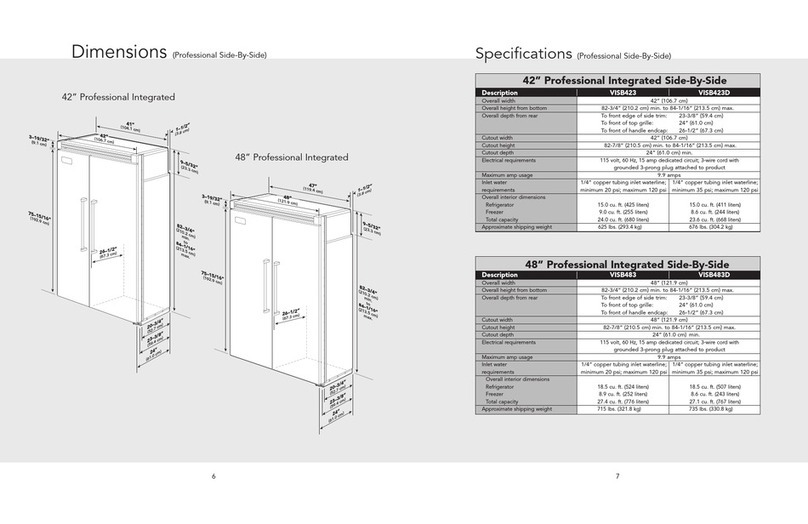
Specifications .................................................................. 6
Warnings........................................................................ 14
Model – Serial Number Matrix ...................................... 15
OPERATION
Settings and Functions .................................................. 16
Automatic Ice Maker ..................................................... 18
Door Stop Adjustment .................................................. 18
Light Bulb ...................................................................... 18
Door Hinge Adjustment ................................................ 19
Height Adjustment ........................................................ 20
DIAGNOSTICS
Display Panel Operation................................................ 21
Program Modes............................................................. 22
Control Panel................................................................. 22
Mode A Functions ......................................................... 23
Reading Temperature Display ....................................... 23
Freezer Thermistor Temperature ................................... 24
Optional Conventional Defrost ..................................... 24
VCC Compressor Frequency ......................................... 25
Refrigerator Cut-In/Cut-Out Temperature
Differential ..................................................................... 25
Freezer Cut-In/Out Temperature Differential ................ 26
Mode B Functions ......................................................... 27
Automatic Keyboard Functions.....................................27
Door Alarm Delay.......................................................... 28
Max Refrigerator Run Time Duration............................. 29
Max Freezer Run Time Duration.................................... 30
Temperature Offset Calibration..................................... 31
Setting Refrigerator Temperature Offset ....................... 31
Setting Freezer Temperature Offset .............................. 32
Defrost Mode Selection................................................. 33
Forced Defrost............................................................... 33
Forced Compressor Start ..............................................33
Exiting Program Mode .................................................. 34
Special Features ............................................................ 34
Forced Defrost Start ...................................................... 34
Forced Compressor Start ..............................................34
Open Thermistor Detect ............................................... 34
Enter Showroom Mode ................................................. 35
Exit Showroom Mode.................................................... 35
Sabbath Mode Feature for Sabbath Observance..........36
Enter Sabbath Mode ..................................................... 36
Power Loss..................................................................... 36
Exit Sabbath Mode........................................................ 36
Power Disconnect Switch .............................................. 37
Power Up Alarm ............................................................ 37
Door Open Alarm.......................................................... 37
High Temperature Alarm ............................................... 37
Thermistor Alarm........................................................... 38
Temperature Control Operation ...................................38
Refrigerator and Freezer Thermistor (NTC) .................. 38
Description Page
SERVICE DIAGNOSTICS AND PROCEDURES
VCC3 Diagnostic codes................................................... 40
Flashing Cycles................................................................ 40
Diagnostic Procedures..................................................... 40
Parts Location–Control Panel .......................................... 42
Upper Grill Assembly....................................................... 43
Control Panel................................................................... 43
Overlay Switch................................................................. 44
High Voltage Board......................................................... 45
Low Voltage Board .......................................................... 45
Component Testing–High Voltage Board........................46
Component Testing–Low Voltage Board......................... 47
Power Disconnect Switch ................................................ 48
Inverter ............................................................................ 48
Condenser Fan ................................................................ 49
Parts Location–Refrigerator Compartment...................... 50
Light Assembly ................................................................ 51
Fresh Food Fan Assembly ............................................... 51
Interior Light.................................................................... 52
Fresh Food Thermistor .................................................... 53
Plasma Cluster................................................................. 54
Water Filter...................................................................... 54
Parts Location–Freezer Compartment Non-Dispenser.... 55
Parts Location–Freezer Compartment Dispenser............ 56
Ice maker ......................................................................... 57
Component Testing–Ice Maker ....................................... 58
Thermal Cut Out (TCO) ................................................... 59
Auger Motor.................................................................... 60
Freezer Evaporator Fan ................................................... 61
Freezer Thermistor .......................................................... 63
Defrost Heater ................................................................. 63
Defrost Terminator........................................................... 65
Float Switch ..................................................................... 66
Water Valve Non-Dispenser ............................................66
Dual Water Valve System Dispenser................................ 66
Drain Pan Heater ............................................................. 67
Parts Location Dispenser................................................. 68
Dispenser Assembly ........................................................ 69
Dispenser Bezel............................................................... 69
Crushed/Cubed Switch ................................................... 70
Ice and Water Paddles..................................................... 70
Cavity Cover Assembly.................................................... 71
Ice Dispenser Module Assembly ..................................... 72
Ice Door Switch ............................................................... 73
Water Switch.................................................................... 73
Child Lock Switch ............................................................ 74
Dispenser Light Socket.................................................... 74
Dispenser Heater............................................................. 75
Troubleshooting Guide.................................................... 76
WIRING DIAGRAMS
Schematic Non Dispenser Model.................................... 79
Schematic Dispenser Model (Before 5/19/2010)............ 80
Schematic Dispenser (Before 5/19/2010).................... 81
Schematic Dispenser Model (After 5/19/2010)............ 82
Schematic Dispenser (After 5/19/2010)....................... 83
Wiring and Component testing
High Voltage Board....................................................... 84
Wiring Diagram Dispenser Model (Before 5/19/2010)....85
Wiring Diagram Dispenser Model (After 5/19/2010).... 86
Wiring Diagram Non-Dispenser Model ...................... 87
