Viking 300-IP User manual

Specifications
Information: 715-386-8861
www.VikingElectronics.com
• Large 10-inch diameter horn
• Fully adjustable mounting hardware included
• Quick and easy installation
• SIP compliant, see page two for more information
• PoE powered (class 3, <13 Watts)
• Paging prioritization
• Plays audio from standard multicast sources
• SIP endpoint or multicast group member
• Red call status LED indicator
• Automatic Noise Canceling (ANC) feature for operation in noisy
environments
• Model 300-IP-EWP comes with Enhanced Weather Protection (EWP),
and is designed to meet IP66 Ingress Protection Rating when mounted
with horn pointing downward at least 45 degrees from horizontal. For
more info on Enhanced Weather Protection (EWP), see DOD 859.
• Compatible with Polycom multicast paging
• Built-in high-efficiency 6 Watt class D amplifier
• SIP/Multicast: SIP page, SIP page and zoned multicast receive
• Support for access code to prevent unwanted SIP calls
• Hangs up on: busy signal, time-out, or touch tone command
• Network remote speaker volume control
• Programmable pre-page alert tone
Power: PoE class 3 (<13 Watts)
Dimensions: 10.0” (23.4 cm) diameter, 11.5” (29.2 cm) long
Shipping Weight: 4.1 lbs (1.86 kg)
Operating Temperature: -40° F to 140° F (-40° C to 60° C)
Humidity - Standard Product: 5% to 95% non-condensing
Humidity - EWP Product: Up to 100%
SIP Audio Codecs: G711u, G722 and G711a
Multicast Audio Codecs: G711u and G722
Network Compliance: IEEE 802.3 af PoE, SIP 2.0 RFC3261,
100BASE-TX with auto cross-over
Regulatory Compliance:
CE, FCC Part 15 and Canada ICES-003 Class A
Maximum Output Level: 113 dB SPL @ 1M
Amplifier: 6 Watt class D
Connections: (1) RJ45 10/100 Base-T
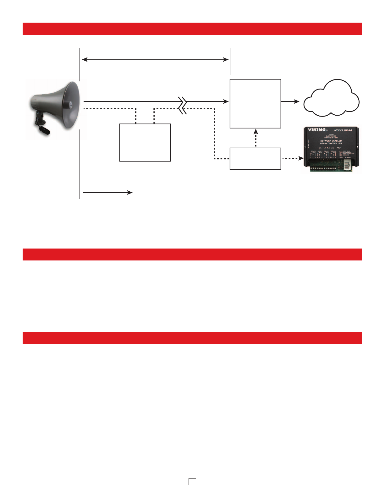
The 300-IP Paging Horn can be used for standard one-way SIP
endpoint paging, multicast paging or background music.
The 300-IP features a high efficiency 6 Watt class D amplifier
capable of driving the horn at up to 113 dB SPL at 1 meter.
The 300-IP-EWP shares all of the features of the 300-IP in
addition to Enhanced Weather Protection (EWP) for outdoor
installations where the unit is exposed to precipitation or
condensation.
EWP products are designed to meet IP66
standards and may feature foam rubber gaskets, sealed
connections, gel-filled butt connectors, as well as potted circuit
boards with internally sealed, field-adjustable trim pots and
DIP switches for easy on-site programming. For more
information on EWP, see DOD 859.
• Amplified SIP endpoint or multicast IP paging for: Schools, Hospitals,
Retail Stores, Office Spaces, etc.
• Provide background music and sound masking
• Background music for: commercial buildings, distribution centers,
service/shop areas, gas stations, indoor/outdoor recreation and sports
facilities, transport terminals, etc.
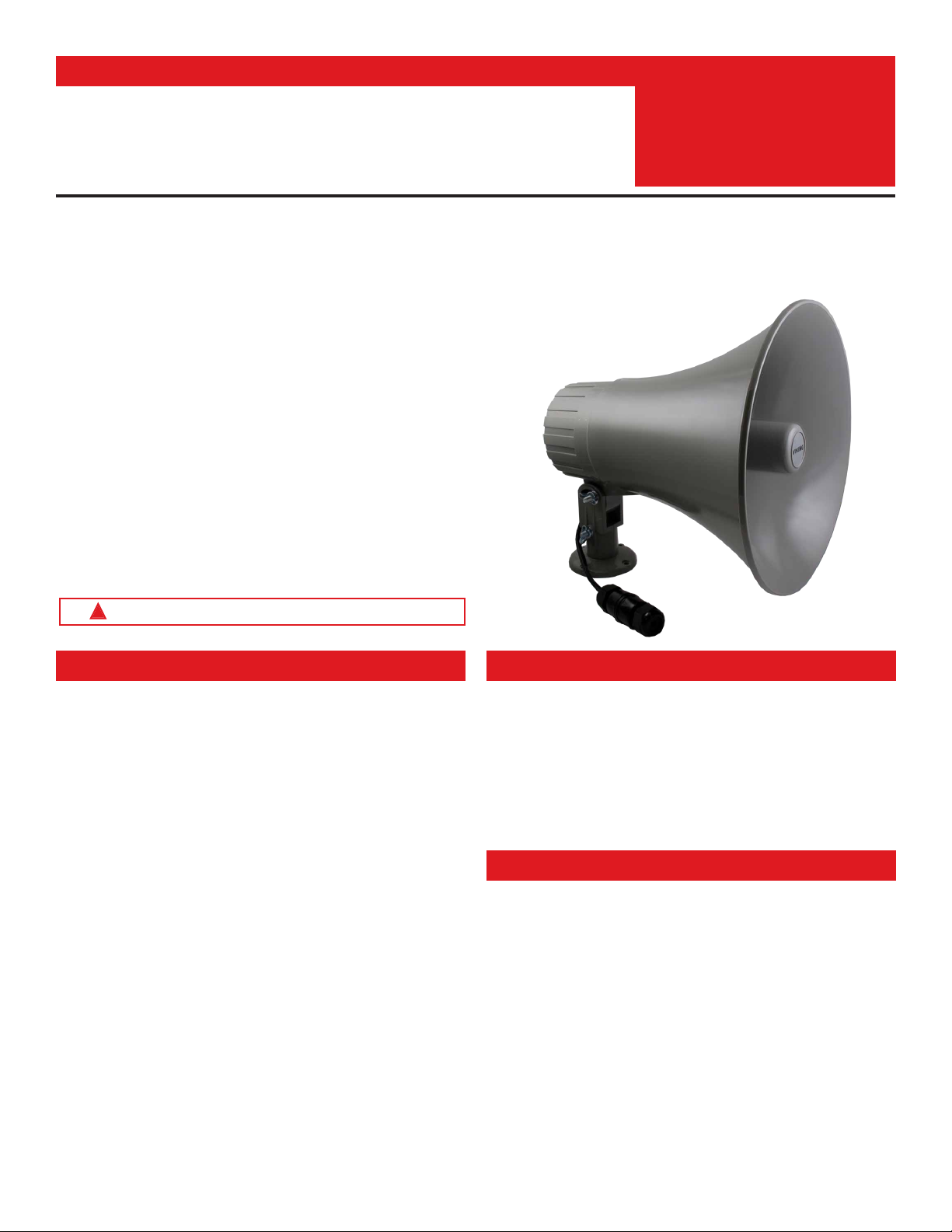
IP Paging Horn for SIP Endpoint Paging or Multicast Paging /
Background Music
Applications
Installation requires a Network Administrator / IT Technician
!
PRODUCT
MANUAL
Designed, Manufactured and Supported in the USA 300-IP
SIP / Multicast
Paging Horn
August 9, 2021
SECURITY & COMMUNICATION
VIKING
Features

2
VoIP SIP System Compatibility
For compatibility and vendor specific detailed configuration instructions, see the Viking VoIP
SIP System Compatibility List, DOD 944. To open and download this PDF file:
1. Go to www.vikingelectronics.com
and enter 944 in the search box
2. Click Application Note (DOD 944)
to open and download the PDF
Scan the QR code below to open
and download the Viking VoIP
SIP System Compatibility List - OR -
Important: Exclusion from this list means only that compatibility has not been verified, it does not mean
incompatibility. If you have questions, please call Viking Electronics at 715-386-8861.

3
Definitions
Client: A computer or device that makes use of a server. As an example, the client might request a particular file from the server.
DHCP: Dynamic Host Configuration Protocol. In this procedure the network server or router takes note of a client’s MAC address and
assigns an IP address to allow the client to communicate with other devices on the network.
DNS Server: A DNS (Domain Name System) server translates domain names (ie: www.vikingelectronics.com) into an IP address.
Ethernet: Ethernet is the most commonly used LAN technology. An Ethernet Local Area Network typically uses twisted pair wires to
achieve transmission speeds up to 1Gbps.
Host: A computer or device connected to a network.
Host Name: A host name is a label assigned to a device connected to a computer network that is used to identify the device in various
forms of network communication.
Hosts File: A file stored in a computer that lists host names and their corresponding IP addresses with the purpose of mapping addresses
to hosts or vice versa.
Internet: A worldwide system of computer networks running on IP protocol which can be accessed by individual computers or networks.
IP: Internet Protocol is the set of communications conventions that govern the way computers communicate on networks and on the
Internet.
IP Address: This is the address that uniquely identifies a host on a network.
LAN: Local Area Network. A LAN is a network connecting computers and other devices within an office or building.
Lease: The amount of time a DHCP server reserves an address it has assigned. If the address isn’t used by the host for a period of
time, the lease can expire and the address can be assigned to another host.
MAC Address: MAC stands for Media Access Control. A MAC address, also called a hardware address or physical address, is a unique
address assigned to a device at the factory. It resides in the device’s memory and is used by routers to send network traffic to the correct
IP address. You can find the MAC address of your 300-IP speaker printed on a white label on the side of the chassis (see page 4).
Router: A device that forwards data from one network to another. In order to send information to the right location, routers look at IP
Address, MAC Address and Subnet Mask.
RTP: Real-Time Transport Protocol is an Internet protocol standard that specifies a way for programs to manage the real-time transmission
of multimedia data over either unicast or multicast network services.
Server: A computer or device that fulfills requests from a client. This could involve the server sending a particular file requested by the
client.
Session Initiation Protocol (SIP): Is a signaling communications protocol, widely used for controlling multimedia communication sessions
such as voice and video calls over Internet Protocol (IP) networks. The protocol defines the messages that are sent between endpoints,
which govern establishment, termination and other essential elements of a call.
Static IP Address: A static IP Address has been assigned manually and is permanent until it is manually removed. It is not subject to the
Lease limitations of a Dynamic IP Address assigned by the DHCP Server. The default static IP Address is: 192.168.154.1
Subnet: A portion of a network that shares a common address component. On TCP/IP networks, subnets are defined as all devices
whose IP addresses have the same prefix. For example, all devices with IP addresses that start with 100.100.100. would be part of the
same subnet. Dividing a network into subnets is useful for both security and performance reasons. IP networks are divided using a subnet
mask.
TCP/IP: Transmission Control Protocol/Internet Protocol is the suite of communications protocols used to connect hosts on the Internet.
TCP/IP uses several protocols, the two main ones being TCP and IP. TCP/IP is built into the UNIX operating system and is used by the
Internet, making it the de facto standard for transmitting data over networks.
TISP: Telephone Internet Service Provider
WAN: Wide Area Network. A WAN is a network comprising a large geographical area like a state or country. The largest WAN is the
Internet.
Wireless Access Point (AP): A device that allows wireless devices to connect to a wired network using Wi-Fi, or related standards. The
AP usually connects to a router (via a wired network) as a standalone device, but it can also be an integral component of the router itself.
Wireless Repeater (Wireless Range Extender): takes an existing signal from a wireless router or access point and rebroadcasts it to
create a second network. When two or more hosts have to be connected with one another over the IEEE 802.11 protocol and the distance
is too long for a direct connection to be established, a wireless repeater is used to bridge the gap.

4
Features Overview
Reset Wires:
Open the waterproof RJ45 connector and remove black wires. Short wires
during power up to reset security code or network parameters to factory
default, see page 9 section E.
MAC Address Label:
The MAC address is a
unique 12 digit number
used by routers to send
network traffic to the
correct IP address.
Back View
PoE LAN Port 10/100, PoE Class 3 (<13 Watts):
Connect to your LAN via RJ45 plug and CAT5 or greater twisted pair wire.
Red Call/Status LED:
Flashes when unit is not
registered, during manual
reset and during dialing, lights
steady when answered.
Front View
Waterproof RJ45 Connector:
Protects the connections from outside
elements. Open to expose Cat5 jack. Route
Cat5 or greater wire through cover. Terminate
wires per T568A or T568B, then tighten cover
to create a seal around the Cat5 wire.

5
Mounting
Step 1. Attach the round mounting plate base to wall, ceiling, post, etc. with appropriate fasteners (not included) (Diagram A).
Step 2. Loosely attach the two side collars to the paging horn using the Philips head bolt, two washers, locking washer, and wing
nut (Diagram B).
Step 3. Slide this assembly onto the mounting plate base (Diagram C). Loosely secure with remaining carriage bolt, washer,
locking washer, and wing nut (Diagram D).
Step 4. With both wing nuts loose, rotate and angle the horn into position, then tighten both wing nuts to secure.
Round
Mounting
Plate Base
Screws
(not included)
(4) 0.217”
diameter 1.99”
3.26”
1.99”
Mounting Plate
Dimensions
SIP / Multicast
P
a
g
in
g
Horn
Status
V
IKING
M
ODEL 300-IP
w
ww.VikingElectronics.com
Side Collars
Phillips
head bolt
WasherWasher
Lock
Washer
Wing
Nut
Round Mounting
Plate Base
SIP / Multicast
P
a
g
in
g
Horn
Status
V
IKING
M
ODEL 300-IP
w
ww.VikingElectronics.com
Carriage
bolt
WasherLock
Washer
Wing
Nut
SIP / Multicas
t
P
a
g
in
g
Horn
Status
V
IKIN
G
M
ODEL 300-IP
w
ww.VikingElectronics.com
Diagram A
Diagram B
Diagram C
Diagram D

6
• IBM compatible personal computer with:
Windows 7, 8 or 10
• Adobe Acrobat Reader 8 or higher
PC Requirements
PC Programming
Typical Installation on SIP Based VoIP Phone System
SIP VoIP PBX
or
PC with
SIP Server
Software
100m (328 ft) maximum*
Viking
supplies
Customer’s
Responsibility
Internet
10/100 Mbps
Maximum
Viking
300-IP
* Note: A PoE extender can be used for an additional 100 meters per extender. For longer
runs (up to 2 km / 1.2 miles) a ethernet to fiber media converter can be used.
Optional
PoE Injector
(If VoIP PBX does
not have PoE) Optional
Switch / Hub
Optional Viking model
RC-4A Secure Remote
Relay Controller, see
page 23 (DOD 582)
(Extends range of cable, keeps
1 Gbps network speed for other
equipment on network)
• Available LAN with PoE (class 3, <13 Watts)
• Ethernet cable (CAT5 minimum)
• 1 MB minimum free hard drive space for installation
• 16MB of free physical RAM
Download and install the programming software
1. Go to www.vikingelectronics.com and enter 300-IP in the search box
2. Click 300-IP in the search results
3. Scroll down the page to Downloads, click IP Programming Software
4. Install the programming software by saving or opening the file and then clicking on setup Viking IP
Programming.exe
5. Follow the prompts on your screen to complete software installation
6. To start the Viking IP Programming application, click on the Viking IP Programming icon on your desk top.
The main screen will appear, allowing the user to program any 300-IP connected to that LAN.
Note: PC must be connected to the same LAN as the 300-IP.

7
A. Connect / Disconnect
Open the “Viking IP Programming” software on the PC and the start screen shown below will appear. Any Viking IP speakers that
are connected to the network will appear on the list. Simply select the 300-IP on the list and click on the “Connect” button at the
bottom or double click the selected speaker. If no username and password have been programmed and the security code of the
selected unit is still set to default (845464), the PC software will not require entering a username, password or security code to
connect to the 300-IP. If the 300-IP has been programmed with a username and password, a pop up window will ask for the username
followed by the password. If the unit’s security code has been changed from “845464”, it will then prompt for the correct security
code. 300-IP’s have a default name of “VIKING_MK64_Vik02”, so if many 300-IP’s are connected to the same network and all have
the default name, MAC addresses must be used to identify each 300-IP.
When finished programming, click the “Disconnect” button at the bottom. Closing the program will also automatically disconnect the unit.
B. Configuring the 300-IP Network Settings
Step 1. Open the “Viking IP Programming” software on a windows PC that is connected to the same LAN as the 300-IP speaker to be
programmed.
Step 2. The window in the upper left corner of the menu will show you each 300-IP speaker that is connected to that LAN. Select the unit with
the same MAC address shown on the label located next to the Ethernet connector on the 300-IP speaker.
Step 3.
Click on the “connect” button. A default 300-IP has no username or password programmed, the security code is set to “845464” and
when configured this way, you are instantly connected to the 300-IP. If the 300-IP has been programmed with a username and
password, a pop up window will ask for the username followed by the password. If the unit’s security code has been changed from
“845464”, it will then prompt for the correct security code, then click “retry”.
Step 4. The program will then read and display the 300-IP speaker’s IP and programming settings.
Step 5. Click on the “IP Settings” tab.
Step 6. Select the appropriate value Static IP Settings or DHCP for “Set Unit IP Address via”. Note: Changing the IP address will cause you to
have to reconnect to the unit. Enter the values for the fields in “if DHCP fails” or “Static IP Settings” as needed.
Step 7. Set the “Unit Name”, “Logging / Time Server Settings” as needed.
Step 8.
Select Peer-Peer in the “SIP Server / Peer to Peer Settings” to use the unit in Peer to Peer mode or for Multicast paging only. Select
Server to register with a SIP registrar server and fill in the “Outbnd Proxy” (SIP Outbound Proxy Server Address, “ip:port”), “Authentic. ID”
(SIP Authentication ID), “Username” (SIP Username, <string>), “Password” (SIP Password), and “Caller ID” (SIP Caller ID) with values
from your VoIP provider. Required fields will be red when the unit is not registered.

8
Step 1. Click on the “VLAN” tab.
Step 2. Disable or enable VLAN tagging by setting the value of “VLAN Tagging”.
Step 3. Set the VLAN tag ID by selecting an integer (1 to PSA-94) in “ID for all packets”.
Step 4. Set the Priority Code Point (PCP) value for all not SIP and RTP packets in the “PCP for all packets” input (0 is default, priorities are
from low to high: 0, 1, 2, 3, 4, 5, 6, 7). Set the “PCP for SIP packets” (3 is default). Set the “PCP for RTP packets” (5 is default).
C. Configuring 300-IP VLAN Settings

9
Step 1. Power down the 300-IP speaker by disconnecting the LAN Cable (RJ45 plug).
Step 2. Provide a short across the Reset wires, then reconnect the LAN Cable (RJ45 plug).
Step 3.
Keep the short across the Reset wires until you hear a single beep, silence and then 2 beeps (approximately 11 seconds). Then
remove the short across the Reset wires. The Status LED will remain off for 5 seconds, light steady for 3 seconds, flash slowly for 3
seconds then fast flash, (after the 2 beeps), indicating when to remove the short across the Reset wires.
Step 4. The security code is now reset to 845464 (factory default).
Step 5. You can now enter programming by following the steps in section A.
D. Manually Resetting the Security Code to Enter Programming
E. Manually Resetting All Network Parameters to Factory Default
Step 1. Power down the 300-IP speaker by disconnecting the LAN Cable (RJ45 plug).
Step 2. Provide a short across the Reset wires, then reconnect the LAN Cable (RJ45 plug).
Step 3.
Keep the short across the Reset wires until you hear a single beep, silence and then 2 beeps (approximately 11 seconds). Continue
with the short across the Reset wires until you hear 4 more beeps (approximately 6 seconds later), then remove the short across the
Reset wires. The Status LED will remain off for 5 seconds, light steady for 3 seconds, flash slowly for 3 seconds (2 beeps) flash fast
for 6 seconds, (4 beeps), then light steady indicating when to remove the short across the Reset wires.
Step 4. You can now enter programming by following the steps in section A.
Programming Features Index
Note:
This procedure will not erase a username and password used to access the 300-IP program mode. Only the security code is set to default.
Note: This procedure will erase a username and password that are used to access the 300-IP program mode.
DESCRIPTION Section Page
Connect / Disconnect A 7
VLAN Settings C 8
Unit Name 1 10
SIP Server 2 10
Peer to Peer Settings 3 10
Outbound Proxy 4 10
Authentication ID 5 10
Register Fails (Re-Resolve or Alternate Server) 6 10
Security Code (factory set to 845464) 7 11
Access Code (1 - 6 digits, blank = Disabled, factory set to 123456) 8 11
Pre Page Tone 9 11
Multicast Page Type 10 11
SIP Page / Call Priority VS Multicast 11 12
Multicast Paging (Standard or Polycom, factory set to Standard) 12 13
Multicast Paging Volume (0 - 19, factory set to 1) 13 13
Night Ring Timed Operation 14 14
Time Zone Settings / Daylight Saving Time 15 14
External Relay (factory set to Disabled) 16 15
Ext Relay Mode
(Door Strike, Paging, Ring, Ring Flash, factory set to Door Strike)
17 15
Ext Relay Activation Command ( 1 or 2 digits, factory set to QQ) NOTE: Relay Mode must be set to Door Strike.
18 15
Ext Relay Activation Time (0.5 - 99 seconds, factory set to 5 seconds) 19 15
Ext Relay Buzz Volume (1 - 3 or Disabled, factory set to 3) 20 16
Ext Relay Latch Commands (Enabled or Disabled, factory set to Enabled) NOTE: Relay Mode must be set to Door Strike 21 16

10
Programming Features Index
DESCRIPTION Section Page
SIP Paging Volume (0 - 19, factory set to 1) 22 16
Ring Volume (0 - 19, factory set to 5) 23 16
SIP Page Length Time Out (Disabled or 1 - 9 minutes, factory set to 3 minutes) 24 16
Multicast Page Length Time Out (1 - 255 seconds, factory set to 180 seconds) 25 16
Inbound Call Mode (Disabled, Auto Answer, Auto Answer-Secure, Ring, factory set to Auto Answer) 26 16
Ring Cadence (factory set to Normal Ring = 2 seconds ON, 4 seconds OFF) 27 17
Mute Current / Next Alarm 28 17
Permanent Alarm Mute 29 17
Programming Username and Password 30 17
IP Firmware 31 18
Unit Firmware 32 18
Import / Export 33 18
Clear Speaker Settings 34 18
Clear IP Settings 35 18
Diagnostics (used to check External relay operation) 36 18
3. Peer to Peer Settings
2. SIP Server
When set to Peer to Peer mode, a SIP server is not used. The unit should be programmed with a static IP address and
username, a password is not used. Caller ID can be programmed if needed. Simply call the unit by entering the
programmed “[email protected]...(static IP address for the unit)”. The static IP address is normally programmed into
a page button on the VoIP telephones. NOTE: Peer to Peer mode does not affect multicast paging.
1. Unit Name
Up to a 30 character unit name can be assigned to the 300-IP being programmed.
Programming Features
Enter the IP address or URL of your SIP server or service provider in this field. The SIP server IP address is limited to
74 characters. Note: If an alternate SIP server IP address is programmed, the IP address for the SIP server and
alternate SIP server will be limited to 31 characters. Note: If outbound proxy is not required, enter the SIP server IP
address into the Outbnd Proxy field.
4. Outbound Proxy
If your SIP provider requires an outbound proxy IP address enter it in the “Outbnd Proxy” field. If outbound proxy is not
required enter the SIP sever IP address into the “Outbnd Proxy” field. NOTE: If not required, this field must match your
SIP server IP address.
5. Authentication ID
If your SIP provider requires Authentication ID, enter it in the “Authentic. ID” field. If Authentication ID is not required,
leave this field blank.
6. Register Fails (Re-Resolve or Alternate Server)
When registered to a SIP server in the event that registration is lost you can program the unit to re-resolve using the
current SIP server IP address or route pages through an alternate SIP server. With Alternate Server selected enter the
IP address of the alternate SIP server in the field next to the Register Fails drop down box. Note: With an alternate
SIP server IP address programmed, the IP address for the SIP server and alternate SIP server will be limited to 31
characters.

11
Standard Multicast Paging Tab
The security code allows the user/installer to program the 300-IP with a PC and the required ‘Viking IP Programming”
software. If the security code is left as default, the PC software won’t require entering a security code when connecting
to the 300-IP. It is recommended that the factory set security code be changed. The security code can be set back to
default by holding the Reset button while the 300-IP powers up. See section D on page 9 for details. It can also be
defaulted by connecting to the unit with the IP Programming Software and clicking on the “Clear Speaker Settings”
button on the “Alarm / Firmware” tab. Factory Setting: 845464
NOTE: The security code must be 6 digits and cannot include a Qor #.
7. Security Code
Select Standard or Polycom as the source of multicast paging. If Polycom is selected as the source, the screen will
change to show its options (see next page). For Details see #12 on Page 13.
Factory Setting: Standard (shown above)
9. Pre Page Tone
When enabled, a short beep will be heard prior to SIP or Multicast paging audio. The volume of the Pre Page Alert Tone
will match the volume setting of the SIP or Multicast page. Factory Setting: Enabled
10. Multicast Page Type
The Access Code is primarily used along with the “Auto Answer Secure” Inbound Call Mode to force inbound SIP page
callers to dial the Access Code before they can make a SIP page. The Access Code also comes into play when using
the relay of the 300-IP to open a door or gate. When you call the 300-IP and the unit automatically answers the call
(see Programming section 38), you must dial the Access Code before you are allowed to operate the door strike relays,
as extra security on inbound calls. Once a tenant has entered the correct Access Code, 2 beeps are heard and the user
can now enter any “Operation Commands” (see Operation section D). The Access Code can be disabled if this basic
security is not required. Factory Setting: 123456
Note: The Access Code can be 1 - 6 digits in length and cannot include a Qor # or match the numbers used for the
Security Code.
8. Access Code

12
Polycom Multicast Paging Tab
Incoming 300-IP SIP call audio streams can be programmed to have priority over any of the 10 standard Multicast
paging groups. Simply use the “Sip Page Priority Level” drop down menu to select which Multicast group you want SIP
calls to have priority over. Factory Setting: “0” (SIP is highest priority).
When Polycom is selected as the Multicast Page Type, the “SIP Page Priority Level” can be set to “Polycom” or “None”.
See the following tables for the order of priorities with each setting. As shown, Polycom Group 25 multicast is the
highest priority. The priority options allow you to determine the priorities for Polycom Groups 1 through 24 multicast
signals and SIP paging. Factory Setting: Polycom
11. SIP Page Priority over Multicast Page
Paging Priorities (SIP Page Priority Level set to
“Polycom”)
Paging Priorities (SIP Page Priority Level set to
“None”)
Polycom Group 25 Polycom Group 25
SIP Paging Polycom Groups 1-24
Polycom Groups 1-24 SIP Paging

13
12. Standard or Polycom Multicast Paging
Standard
When using standard Multicast Paging, up to 10 multicast paging groups can be programmed into each 300-IP paging
horn. Each multicast group is defined by a multicast address and port number. Each multicast group is assigned a
priority, allowing simultaneously arriving pages to be serviced based on importance. A timeout check box can be
selected for each paging group. See Multicast Page Timeout under Paging Settings to adjust the timeout from 1 - 255
seconds. Only one timeout time can be programmed for all groups. The volume for each multicast group can be
programmed separately.
Assigning Priority to standard Multicast Paging
The 300-IP will prioritize simultaneous audio streams according to their priority in the Paging Sources list. Group 0 will
have the highest priority while group 9 will have the lowest priority. Group 9 is useful for a low priority stream such as
background music. Group 0 is useful for high priority streams such as emergency messages.
The multicast paging groups can also be used for up to ten different paging zones for receiving audio streams. A paging
zone can consist of one or many 300-IP multicast paging horn. There is no limit to how many speakers can be in a
given paging zone. Each multicast group is defined by a multicast address and port number. Each multicast group is
assigned a priority, allowing simultaneously arriving pages to be serviced based on importance.
Polycom
Polycom IP phones send multicast audio to a specific IP address and port. A total of 25 groups can be used, with
group 25 generally reserved for an emergency broadcast. Set the Multicast Page Type to “Polycom”. The Viking IP
programming page will then show “Polycom Paging Source and Group Subscriptions”. Polycom phones will default
to IP address 224.0.1.116 and port 5001 for multicast. Under “Polycom Paging Source and Group Subscriptions”,
enter the IP address and port you chose in the Polycom IP phone as “Multicast IP address” and “port” (Paging/PTT
Configuration page). Select the paging groups the 300-IP should subscribe to. Any multicast audio sent to the
correct IP address, port number and a subscribed group will be heard from the Speaker terminals. Group 1 is the
lowest priority and group 25 is the highest. The Volume and Timeout can be selected globally, although the timeout
does not affect group 25. Factory Setting: all Groups selected
The volume of each individual standard multicast page can be adjusted from 0 - 19. When polycom paging is used,
the paging volume is set globally for all 25 groups. Factory Setting: 1
13. Multicast Paging Volume

14
14. Night Ring Timed Operation
When Night Ring Timed Operation is enabled, if a SIP call is received during the programmed Start and Stop times,
the 300-IP will output loud ring. This is selectable for each day of the week. When outside of the Night Ring timing
window, the Inbound Call Mode setting will determine how SIP calls are handled. NOTE: For timed Night Ringing the
unit must be synced with a time server. If the Night Ringing feature is enabled in the software you will be asked to use
Viking Time Server when changes are applied. The address will be entered by the software automatically.
15. Time Zone Settings / Daylight Savings Time
When using the Night Ring Timed Operation the 300-IP must be synced with the network time. Set the Time Zone
Settings to match the settings on the network the unit is connected to for proper timed operation.

15
16. External Relay
A Viking remote model RC-4A relay controller can be used to activate up to four external relays (see page 21). With
the external relay set to “EXT 1,2,3,4,” the 300-IP will activate an optional RC-4A relay controller.
Factory Setting: Disabled
17. Ext Relay Mode
Door Strike Mode: When programmed for Door Strike Mode the relay is intended for door strike, magnetic lock or
gate control.
Paging Mode: When programmed for Phone/Paging Mode the relay will activate continuously for the duration of any
SIP or multicast page or any inbound or outbound call to or from the speaker phone. This mode is useful for triggering
paging amplifiers, etc.
Ring Mode: When programmed for Ring Mode the relay will continuously activate while the ringing extension is called.
This mode is useful for activating a Viking model SL-2 strobe light, etc.
Ri
ng Flash Mode: When programmed for Ring Flash Mode the relay will momentarily turn on and off in a 400 ms on/off
cadence while the ringing extension is called. This mode is useful for activating a Viking LPL-1 Remote Visual Indicator, etc.
The one or two digit code stored in the Ext Relay Command is the touch tone command that the person calling the
300-IP must enter on their phone in order to momentarily activate the relay to control a door strike, magnetic lock, gate
controller, or other device. The code can contain the characters 0-9, # or Q. The code cannot match a relay latching
command (Q1, Q0). The code must be entered while the remote phone is communicating with the 300-IP.
Factory Setting: QQ.
18. Ext Relay Command
The value stored in the Relay Activation Time is the amount of time the relay will be energized after a correct momentary
touch tone command is entered. This number can range from 0.5 - 99 seconds. Factory Setting: 5 seconds
19. Ext Relay Activation Time

16
The relay activation tone is a buzzing sound that is heard from the speaker when the door strike relay is activated.
After the caller enters the correct relay activation command, the caller will hear 2 short confirmation beeps and the
speaker will output a buzzing sound (relay activation tone) while the door strike relay is activated. The tone (buzz)
length will match the relay activation time up to a maximum of 5 seconds. The tone (buzz) can be programmed to three
different volume settings 1 = Low, 2 = Medium, 3 = High or it can be disabled. When disabled, the confirmation beeps
will not be heard. Factory Setting: 3
20. Ext Relay Buzz Volume
When set to “Enabled” the Operation Commands (Q0 to Q1) to Un-Latch or Latch the relay are enabled. These can be
entered on a inbound call after the access code is dialed (if programmed).
When set to “Disabled” the Operation Commands (Q0 to Q1) to Un-Latch or Latch the relay are disabled. Disabling the
latch commands can be useful in applications where you want to eliminate the possibility of inadvertently entering a
latch command leaving a gate open/closed, etc.
Factory Setting: Enabled
21. Ext Relay Latch Command
The SIP Paging volume can be set from 0 - 19. 0 = lowest volume setting, 19= highest volume setting. Adjusting this
will set the Speaker volume level for SIP Paging. This setting does not affect multicast volume settings.
Factory Setting: 1
22. SIP Paging Volume
When the Inbound Call mode is set to Ring or Night Ring timed operation is in effect, the 300-IP will output a loud ring
when it is called. The level can be adjusted from 0 - 19. Factory Setting: 5
23. Ring Volume
The Inbound Call Mode determines how the 300-IP handles incoming SIP calls. One option is to generate a loud ring
sound through the speaker. The 300-IP can also auto answer a SIP call to transmit a page or control the relay. The
“secure” options for auto answer require the callers to dial the access code in order to transmit a page or activate the
optional RC-4A relays. Factory Setting: Auto Answer
Disabled: Inbound SIP calls are not allowed.
For more security use the Auto Answer Secure Mode.
Auto Answer: Inbound calls are auto answered on the first ring. For more security use the Auto Answer Secure Mode.
Auto Answer Secure: Inbound SIP calls are auto answered and the caller must dial the access code in order to make
a SIP page.
Ring: In the “Ring” mode the speaker phone will not automatically answer an incoming call but will output a loud ring
signal out of the speaker in a factory programmed 2 seconds ON, 4 seconds OFF ring pattern. There are four available
ring cadences.
26. Inbound Call Mode
This feature selects the maximum length of time that SIP Paging calls can be connected. Programmable in increments
of 1 minute up to a maximum of 9 minutes or disabled. With the SIP aging length disabled, the 300-IP paging horn
must rely on a call ended signal or touch tone # to hang-up. Factory Setting: 3 minutes
24. SIP Page Length Timeout
The Multicast Page Length Timeout can be programmed from 1 - 255 seconds in one second increments. The Time
Out can be disabled, allowing any length of page or continuous background music. Only one timeout time can be
programmed for all multicast paging groups. When using standard Multicast Paging, a timeout checkbox can be selected
for each paging group. When using Polycom Multicast Paging, the timeout checkbox enables the timeout globally on
groups 1 through 24. There is no timeout for a page to the emergency group 25.
Factory Setting: 180 seconds
25. Multicast Page Timeout

17
30. Programming Username and Password to Restrict Access to Programming
To increase security, a username and password can be programmed to limit access to the 300-IP using Viking IP
Programming software. When no username and password are programmed and the security code is still set to default
(845464), the PC software will not require a username, password or security code when connecting to the 300-IP. If
the 300-IP has been programmed with a username and password, a pop up window will ask for the username followed
by the password. If the unit’s security code has been changed from default (845464), it will then prompt for the correct
security code.
If the username and password are unknown, they can only be erased by resetting all network parameters to default
with the reset button (see section E on page 9). If the username and password are known but you wish to erase them,
that can be accomplished by exporting the data from the 300-IP (“Alarm / Firmware” tab of Viking IP Programming),
resetting all network parameters to default with the reset button (see section E on page 9) and then importing the data
back into the speaker.
27. Ring Cadence
The Ring Cadence can be programmed to one of four different cadences. Factory Setting: Normal Ring
Normal Ring (single ring: 2 seconds ON, 4 seconds OFF)
Double Ring (double ring: 1 second ON, 0.5 second OFF, 1 second ON, 3.5 seconds OFF)
Short-Short-Long (triple ring: 0.5 second ON, 0.5 second OFF, 0.5 second ON, 0.5 second OFF, 1 second ON, 3 seconds OFF)
Short-Long-Short (triple ring: 0.5 second ON, 0.5 second OFF, 1 second ON, 0.5 second OFF, 0.5 second ON, 3 seconds OFF)
29. Permanent Alarm Mute
28. Mute Current / Next Alarm
A network failure alarm will be indicated by providing 3 beeps over the speaker every 30 seconds but only when Permanent
Alarm Mute is set to Alarm Tones Enabled (Permanent Alarm Mute is set to Alarm Tones Disabled by default). A network
failure indicates the unit is not registered to the SIP server or there is a communication failure with the gateway. The three
beeps can be muted by clicking on “Mute Current / Next Alarm” button in the IP Programming software or provide a short
across the reset wires for five seconds. The Status LED will continue to flash to assist troubleshooting. The alarm beeps can
also be permanently disabled. See Permanent Alarm Mute below. Factory Setting: Disabled
Permanent Alarm Mute is set to Alarm Tones Disabled by default, so network failure alarms will not be indicated over the
speaker. Only the status LED will flash to indicate the network failure. To enable alarm tones over the speaker, select Alarm
Tones Enabled.

18
32. Unit Firmware
If new 300-IP firmware is available, after opening the programming software a pop up window will ask if you would like
to update firmware. Another way to update is accomplished by clicking the speaker firmware “Update Unit” button. You
can then browse to the folder that contains the HEX file for updating the unit’s firmware. This method is typically only
used when Viking Technical Support has sent you updated firmware.
33. Import / Export
The Import / Export feature is useful for backing up all the 300-IP’s programming or for importing programming when
installing multiple units with a majority of the same programming.
Clicking on the “Clear Speaker Settings” button in programming will reset all of the Programming Features back to
their factory default settings. NOTE: This command will not change or reset your IP settings.
34. Clear Speaker Settings
Clicking on the “Clear IP Settings” will reset all of the IP settings back to their factory default settings. This also clears
paging Group settings and Addresses. NOTE: This will not affect any speaker or paging settings.
35. Clear IP Settings
36. Diagnostics
The Diagnostics section in the Viking IP Programming can be used to test the functionality of the optional RC-4A relays.
31. IP Firmware
Update IP is currently not available. The ability to update IP firmware will be made available in a later release of Viking
IP Programming software. If an IP firmware update is needed, Viking Technical Support will assist in updating the IP
firmware.

19
Operation
A. Inbound SIP Calls
How inbound SIP calls are handled depends on the Inbound Call Mode selected (see Programming section 26), the
current programming for Night Ring Timed Operation if enabled (see Programming section 14), the current time of day
and day of week. If Night Ring Timed Operation is disabled and the Inbound Call Mode is set to Auto Answer, the 300-IP
will automatically answer inbound calls, provides a Pre Page Alert Tone if enabled and allows paging through the unit.
When the Inbound Call Mode is set to Auto Answer – Secure, the 300-IP auto answers inbound calls but the party must
dial the Access Code before they are allowed to page from the unit. The Inbound Call Mode also has options that allow
the unit to output a loud ring on any inbound SIP calls. The Ring option outputs a fixed volume ring and is adjustable
(see Programming section 23). If Night Ring Timed Operation is enabled and an inbound SIP call is received between
the programmed start and stop times and the current day is a programmed active day, the unit will automatically output
a loud ring instead of following the Inbound Call Mode programming. This allows for loud ring at certain times of the
day/days of the week and paging all other times/days of the week.
B. Multicast
The 300-IP can be set to one of two modes for multcasting, Standard or Polycom. Polycom is only used when Polycom
IP phones are used. To change to Polycom multicast, go to the “Paging” tab and change the “Multicast Page Type” to
Polycom.
Standard Multicast Paging (Factory Setting)
Up to 10 multicast paging groups can be programmed into each unit and each group is assigned a priority level allowing
simultaneous arriving multicast pages to be handled based on importance. Low priority groups are often used for low
priority streams like background music and high priority groups are used for high priority streams such as emergency
messages. Group 0 is the highest priority, and Group 9 is the lowest. A timeout limit can be set and either enabled or
disabled for each multicast group. The volume of each group can be programmed and SIP Paging can be assigned
either higher or lower priority than all or some of the multicast groups (see Programming section 11).
Polycom Multicast Paging
Polycom phones send multicast audio to a specific IP address and port. A total of 25 groups can be used and groups
1 through 24 can individually be enabled/disabled in each 300-IP. Group 25 is always enabled, as group 25 is generally
used for emergency broadcasts. Any multicast page made from a Polycom phone (on the same LAN) to the
programmed IP address, port and to an enabled group will play through the 300-IP paging horn. The priority of Polycom
sources ranges from group 1 (lowest) to group 25 (highest). SIP Paging can be assigned either higher or lower priority
than Polycom group 1 through 24 multicast paging (see the table in programming section 11 for Polycom paging
priorities). Multicast page timeout can be enabled/disabled globally for groups 1 through 24 (there is no timeout for
group 25) and the length of the Multicast page timeout is adjustable. The volume for Polycom multicast is set globally
for all groups.

20
C. Operation Commands (Relay Mode must be set to “Door Strike”)
Feature Tone Tone
Command Description
Activate
Ext Relay
QQ or
___ ___ Momentarily activate ext relay (1 or 2 digits, factory set to QQ).
Un-Latch
Ext Relay Q0Un-latch* (deactivate) the ext relay.
Latch
Ext Relay Q1Latch* (continuously activate) the ext relay.
Disconnect # Disconnects or forces the speaker to hang up.
* NOTE: Latching commands must be enabled in programming.
The following commands can be entered after the 300-IP answers an inbound SIP call, when the Inbound Call Mode
is set to auto answer. After the unit auto answers the call, one beep will be heard if Pre Page Alert Tone is enabled. If
the Access Code has been disabled, you can now enter the Operation Commands listed below. If an Access Code has
been programmed, enter the Access Code digits. Once the correct code has been entered, two beeps will be heard
and you can now enter the Operation Commands listed below.
Troubleshooting
If the unit cannot register with the programmed SIP server, the “Status” LED will blink on and off every two seconds until
communication is restored. This alerts a potential user of a problem with the device that will prevent SIP calls from being
accepted.
This manual suits for next models
1
Table of contents
Other Viking Speakers manuals