Viking 40TB-IP User manual

PRODUCT MANUAL
Designed, Manufactured and Supported in the USA
SECURITY & COMMUNICATION SOLUTIONS
VIKING
Features
Specifications
Information: 715-386-8861
www.VikingElectronics.com
• PoE powered (class 2, <6.5 watts)
• Use with an optional BTR-3 Bluetooth wireless remote to activate calls or
adjust speaker volume (see DOD 504)
• Paging prioritization
• Plays audio from multicast
• SIP endpoint or multicast group member
• Supports up to 10 multicast paging groups
• Add an optional SL-2 blue, green, red or amber strobe light (see DOD 242)
• Blue call status LED indicator
• SIP compliant (see pageg 2 for list of compatible IP-PBX phone systems)
• Automatic Noise Canceling (ANC) feature for operation in noisy environments
• Viking’s proprietary VOX switching eliminates the need for “Push to Talk” mode
• Selectable auto-answer feature for monitoring
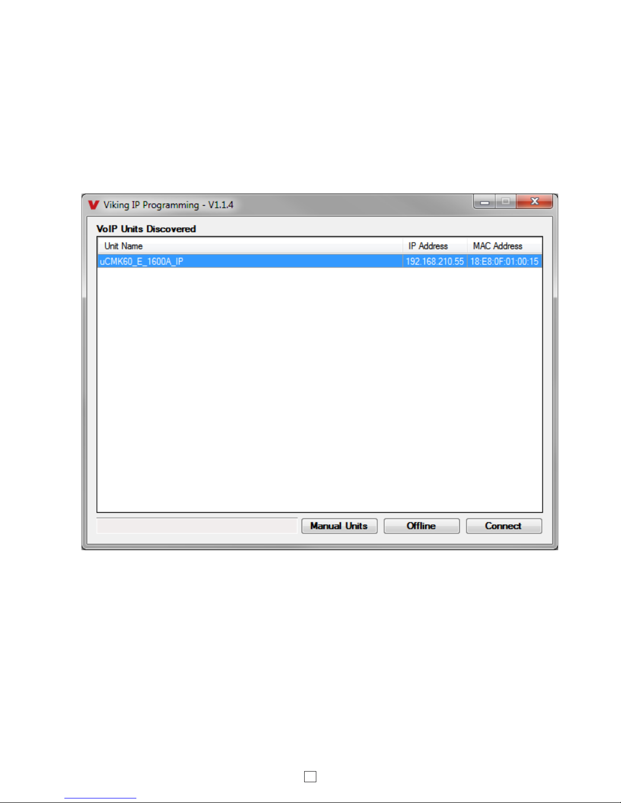
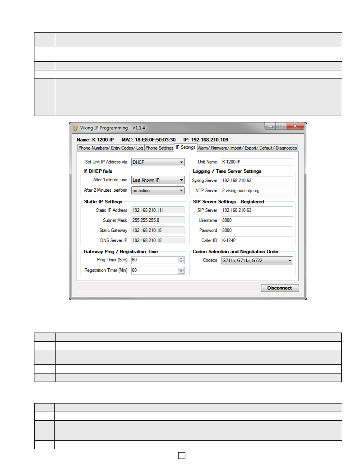
• Autoprovisioning via Viking programming software
Power: PoE class 2 (<6.5 watts)
Dimensions: Overall: 11” x 11” x 4” (279mm x 279mm x 102mm)
Back box: 9.25” x 9.25” x 3.45” (235mm x 235mm x 88mm)
Shipping Weight: 5.0 lbs (2.27 kg)
Operating Temperature: -40°F to 140°F (-40° C to 60° C)
Humidity - Standard Products: 5% to 95% non-condensing
Audio Codecs: G711u, G722 and G711a (SIP only)
Network Compliance: IEEE 802.3 af PoE, SIP 2.0 RFC3261, 100BASE-TX with
auto cross over
Connections: (1) RJ45 10/100 Base-T, (1) 8 position terminal block
Sensitivity: 96dB / 1W / 1M S.P. Level
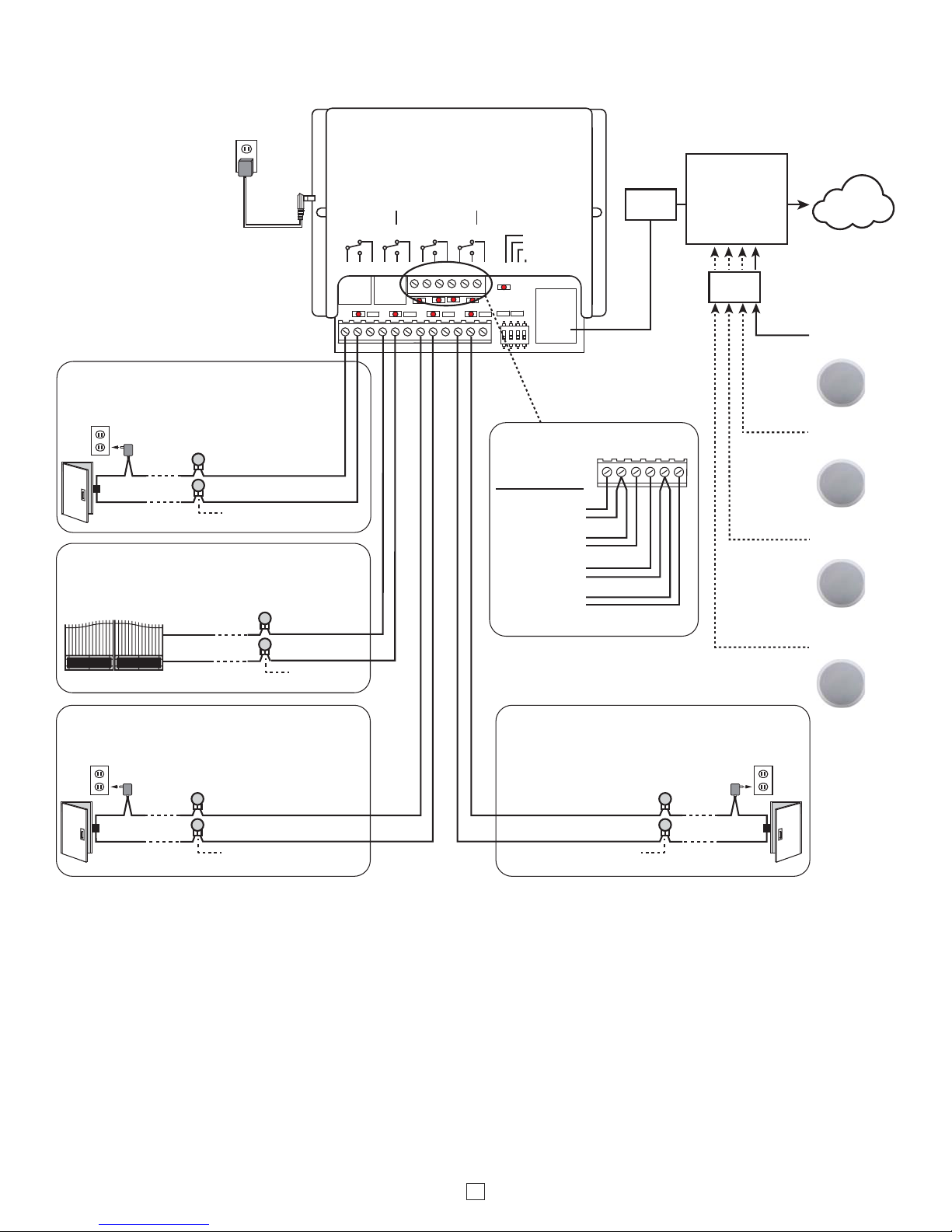
The Viking model 40TB-IP Talk-Back Ceiling/Wall Speaker enables
two-way conversations via SIP and also allows for standard paging
and background music via multicast. The Talk-Back Speaker easily
connects with a single CAT5/6 cable from your PoE switch. Its
shallow depth allows the speaker to be conveniently mounted in a
standard 2” x 4” stud wall or ceiling.
An auxiliary switch input allows a hard wired wall button to initiate a
SIP call. Alternately, an optional wireless Bluetooth remote call button
can be used (Viking model BTR-3, sold separately). A momentary
button press will initiate a standard call, and holding the button for 3
or more seconds will initiate an emergency call. The remote can also
be used to adjust the speaker volume. The LED on the 40TB-IP can
be programmed to blink when there is call activity.
The integrated microphone enables talk-back and also monitors room
noise to automatically increase speaker volume when necessary.
Line-level audio output connections are provided for connecting to
an external amplifier. Speaker output connections are also provided
to directly drive additional analog speakers.
• Built-in high efficiency 4 watt class D amplifier
• Relay for activating door locks, strobe lights, external amplifiers, etc.
• SIP/Multicast: SIP page, SIP page and zoned multicast stream, zoned
multicast receive
• Support for access code to prevent unwanted SIP calls
• Line-level audio output for connecting to an external amplifier
• Hangs up on: busy signal, time-out, or touch tone command
• Network and Bluetooth remote speaker volume control
• Can drive additional external analog speakers for greater coverage
• Mounting: Blind mounts into 9.5” hole, clearance requirement of 3.45”
(87.3mm) above 1/2” gypsum board ceiling
• Heavy duty back box protects speaker and circuitry against plenum dust
• Automatic Gain Control (AGC) to automatically increase ring volume to
compensate for ambient noise
• Amplified SIP endpoint or multicast IP paging for: schools, hospitals,
retail stores, office spaces, etc.
• Provide background music and sound masking
• Make standard and/or emergency SIP phone calls via hands free
talkback speaker
• Background music and emergency calls for elevator applications
40TB-IP
SIP / Multicast Talkback
Ceiling Speaker
April 3, 2017
IP Ceiling Speaker for SIP Endpoint Paging or Multicast
Paging/Background Music, and Making Standard or Emergency SIP Calls
Model BTR-3 Wireless
Bluetooth Remote
(sold separately,
see DOD 504 for info)
Applications
Installation requires a Network Administrator / IT Technician
!
Model
40TB-IP
A programmable relay output is provided for activating door locks,
strobe lights, external amplifiers, etc.
(front view) (side view)

2
Viking VoIP SIP System Compatibility List
NOTE: Exclusion from this list means only that compatibility has not been verified, it does not mean incompatibility.
For detailed configuration instructions for certain vendors below, see Configuring Viking VoIP Phone and SIP
Servers,DOD# 944.
* Note: Not compatible with ShoreTel Ring Group/Hunt Group (unit can be programmed to ring an extension 2 or 3 times then roll to the next number, for
a total of 5 numbers).
** Note: Relay operation commands are Not compatible with Panasonic Phone Systems (Panasonic does not transmit DTMF between station ports).
Known Incompatible System or Service Provider: Ring Central (Requires Authorization ID and Proxy address).
Vendor
Infrastructure Class
Softswitch PBX Proxy SBC
(session border
controller)
Service
Provider
3COM VCX X
3CX X
Aastra X
Asterisk X
Atcom X
Avaya Aura Communication Manager X
Avaya IP Office X
BlueBox X
Brekeke X
Callcentric X
Cisco Unified Communications Manager (CUCM) X X
Cisco Unified Communications Manager Express
(CUCME) X X
Elastix X
Epygi QX200 X
Freeswitch X
Grandstream X
Interactive Intelligence X X
iPECS (Ericsson-LG) X
iptel.org X
Kamailio X X
MetaSwitch XX
NEC X
OfficeSIP X
OpenSIPS X
Panasonic** (with SIP Extension Card) X
Samsung Communications Manager (SCM) X X
ShoreTel* X
Siemens Communications Server (SCS) X
SIP Express Router (SER) X X
sip.antisip.com X
Snom PBX X
Sonus X
Switchvox X X
Teksip X
Toshiba X
VoIP.ms X

3
Definitions
Client: A computer or device that makes use of a server. As an example, the client might request a particular file from the server.
DHCP: Dynamic Host Configuration Protocol. In this procedure the network server or router takes note of a client’s MAC address and
assigns an IP address to allow the client to communicate with other devices on the network.
DNS Server: A DNS (Domain Name System) server translates domain names (ie: www.vikingelectronics.com) into an IP address.
Ethernet: Ethernet is the most commonly used LAN technology. An Ethernet Local Area Network typically uses twisted pair wires to
achieve transmission speeds up to 1Gbps.
Host: A computer or device connected to a network.
Host Name: A host name is a label assigned to a device connected to a computer network that is used to identify the device in various
forms of network communication.
Hosts File: A file stored in a computer that lists host names and their corresponding IP addresses with the purpose of mapping addresses
to hosts or vice versa.
Internet: A worldwide system of computer networks running on IP protocol which can be accessed by individual computers or networks.
IP: Internet Protocol is the set of communications conventions that govern the way computers communicate on networks and on the
Internet.
IP Address: This is the address that uniquely identifies a host on a network.
LAN: Local Area Network. A LAN is a network connecting computers and other devices within an office or building.
Lease: The amount of time a DHCP server reserves an address it has assigned. If the address isn’t used by the host for a period of
time, the lease can expire and the address can be assigned to another host.
MAC Address: MAC stands for Media Access Control. A MAC address, also called a hardware address or physical address, is a unique
address assigned to a device at the factory. It resides in the device’s memory and is used by routers to send network traffic to the correct
IP address. You can find the MAC address of your 40TB-IP phone printed on a white label on the top surface of the PoE LAN port.
Router: A device that forwards data from one network to another. In order to send information to the right location, routers look at IP
Address, MAC Address and Subnet Mask.
RTP: Real-Time Transport Protocol is an Internet protocol standard that specifies a way for programs to manage the real-time transmission
of multimedia data over either unicast or multicast network services.
Server: A computer or device that fulfills requests from a client. This could involve the server sending a particular file requested by the
client.
Session Initiation Protocol (SIP): Is a signaling communications protocol, widely used for controlling multimedia communication sessions
such as voice and video calls over Internet Protocol (IP) networks. The protocol defines the messages that are sent between endpoints,
which govern establishment, termination and other essential elements of a call.
Static IP Address: A static IP Address has been assigned manually and is permanent until it is manually removed. It is not subject to the
Lease limitations of a Dynamic IP Address assigned by the DHCP Server. The default static IP Address is: 192.168.154.1
Subnet: A portion of a network that shares a common address component. On TCP/IP networks, subnets are defined as all devices
whose IP addresses have the same prefix. For example, all devices with IP addresses that start with 100.100.100. would be part of the
same subnet. Dividing a network into subnets is useful for both security and performance reasons. IP networks are divided using a subnet
mask.
TCP/IP: Transmission Control Protocol/Internet Protocol is the suite of communications protocols used to connect hosts on the Internet.
TCP/IP uses several protocols, the two main ones being TCP and IP. TCP/IP is built into the UNIX operating system and is used by the
Internet, making it the de facto standard for transmitting data over networks.
TISP: Telephone Internet Service Provider
WAN: Wide Area Network. A WAN is a network comprising a large geographical area like a state or country. The largest WAN is the
Internet.
Wireless Access Point (AP): A device that allows wireless devices to connect to a wired network using Wi-Fi, or related standards. The
AP usually connects to a router (via a wired network) as a standalone device, but it can also be an integral component of the router itself.
Wireless Repeater (Wireless Range Extender): takes an existing signal from a wireless router or access point and rebroadcasts it to
create a second network. When two or more hosts have to be connected with one another over the IEEE 802.11 protocol and the distance
is too long for a direct connection to be established, a wireless repeater is used to bridge the gap.

4
Features Overview
Microphone: Omni-directional microphone
with protective water-resistant cloth.
Speaker: 8” paper with wizzer cone
Blue Call/Status LED: Flashes during
dialing, then lights steady when answered.
Front View
Switch
Input
Speaker
Out
Relay
Output Contact
(2A@30VDC/ 250VAC max)
MAC Address Label: The
MAC address is a unique
12 digit number used by
routers to send network
traffic to the correct IP
address.
PoE LAN Port 10/100,
PoE Class 2 (<6.5 Watts):
Connect to your LAN via
RJ45 plug and CAT5 or
greater twisted pair wire.
Yellow Network Status
LED: Lights steady to
indicate power and data
link. Blinks to indicate
network activity.
(Power typically not
required for gate controllers)
Doorstrike /
Magnetic Lock
120V AC
Connect to Optional
Doorstrike, Mag
Lock, Gate
Controller, etc.
Green Unit Status LED
+-
- OR -
- OR-
Line Out
Side View
Remove jumper wire when
adding Speakers
Adjustable Mounting
Clamps
VIKING©
VIKING
ELECTRONICS
HUDSON, WI 54016
60 WATT 2 ZONE
POWER AMPLIFIER
PWR 60 W
+/ 24 VDC
MODEL PA-60
SPKRS
PWR
LED
SPKRS
LINE LEVEL
AUDIO INPUT
GAIN GAIN
70V OUT
SPKRS
SPKRS
LINE LEVEL
AUDIO INPUT
70V OUT
CHANNEL 2CHANNEL 1
2315 7101112
46 89
Up to (15)
8 Ohm Speakers
(25AE shown,
not included)
Up to (15)
8 Ohm Speakers
(30AE shown,
not included)
Up to (15)
8 Ohm Speakers
(35AE shown,
not included)
Up to (15)
8 Ohm Speakers
(40AE shown,
not included)
600 Ohm
Paging Audio
Volume
Control
Optional Viking Model
40AE analog speakers
See DOD# 498
Optional Viking Model PA-60 paging
amplier See DOD# 493

5
Installation and Mounting
A. Ceiling or Wall Installation
The 40TB-IP Ceiling Speaker is intended to be mounted in a T-bar acoustic tile, gypsum ceiling or wall. An optional T-Bar support
bracket (SA-TBA) is available that can transfer the speaker weight onto the T-bar rails. Installation instructions are provided with the
support bracket. The metal protective speaker grill must be removed to access the four Phillips head screws that operate the four
clamps. A small wire speaker grill removal tool is provided to remove the grill. The clamp screws must be sufficiently loose to allow
clamps to rotate and clear the ceiling material thickness. When tightened, the clamps are locked to prevent rotating. Removal of the
speaker from the ceiling requires the clamps to be sufficiently loosened before they can rotate in to pass through the 9.5” hole required
in the ceiling. The wiring connections are easiest made prior to mounting if possible. Network connection is made by inserting a RJ45
plug into the jack on the side of the housing. Wire connections for relay input, switch input, speaker output and line level output (if
used) are made using the 8 position pluggable terminal block provided. The back box helps prevent plenum dust from entering the
enclosure. With connections made, lift the housing into the ceiling and tighten the 4 clamps using a #2 Phillips screwdriver until snug.
After installation and testing the speaker grill can then be fastened by adding grill adhesive (provided with grill removal tool) to 4
edges of grill then gently working the speaker grill into its friction fit position and ensure it is evenly flush to the housing around the
edge. The speaker grill is intentionally tight to prevent falling from the ceiling. A speaker grill removal tool supplied with the 40TB-IP
Ceiling Speaker can be used to remove the grill. If lost, a small Allen key or heavy duty paperclip bent into an L shape can be used
to remove the grill by pulling close to the edge.
Applications and Wiring
A. Elevator App

6
Switch
SIP VoIP PBX,
SIP Cloud based
Service Provider
or
PC with SIP
Server Software
Internet
PoE
Switch
LED 8
LED 7LED 6
LED 4
LED 3
LED 2
LED 1 LED 5
LED 9
123
on
4
1234
VIKING
ELECTRONICS
HUDSON, WI 54016
NETWORK ENABLED
RELAY CONTROLLER
MODEL RC-4A
©
VIKING
1
IN1 C IN2 IN3 C IN4
23456
POWER 12V DC
RELAY 1 RELAY 2 RELAY 3 RELAY 4
1234578910 11 12
STATUS
LED
6NETWORK
LOGIC LEVEL
PROGRAMMING
RESTORE DEFAULTS
SPARE
12V DC Adapter
(included)
Sensor
Examples:
Door Sensor
Gate Sensor
Door Sensor
Door Sensor
N.O.
COM.
Connect to Doorstrike,
Mag Lock, Gate Controller, etc.
2 Gel-Filled Butt
Connectors (included)
Doorstrike /
Magnetic Lock
120V AC
Door / Gate Examples:
Door near Entry Phone 1
N.O.
COM.
2 Gel-Filled Butt
Connectors (included)
(Power typically not
required for gate controllers)
Gate Controller
40TB-IP
Speaker 1
40TB-IP
Speaker 2
40TB-IP
Speaker 3
40TB-IP
Speaker 4
Relay 2 Output Contacts (5A@30VDC / 250VAC max)
Connect to Gate Controller, etc.
Gate near Entry Phone 1
N.O.
COM.
2 Gel-Filled Butt
Connectors (included)
Doorstrike /
Magnetic Lock
120V AC
Door near Entry Phone 2
N.O.
COM.
Relay 4 Output Contacts (5A@30VDC /
250VAC max) Connect to Doorstrike,
Mag Lock, Gate Controller, etc.
2 Gel-Filled Butt
Connectors (included)
Doorstrike /
Magnetic Lock
120V AC
Door near Entry Phone 3
1
IN1 C IN2 IN3 C IN4
23456
Relay 1 Output Contacts (5A@30VDC / 250VAC max)
Connect to Doorstrike,
Mag Lock, Gate Controller, etc.
Relay 3 Output Contacts (5A@30VDC / 250VAC max)
For applications requiring additional security, (prevent intruders from removing the speaker and accessing the on board door
strike/gate control relays) a Viking model RC-4A remote relay controller can be used. The relay controller is mounted securely
inside the building and connected to the same LAN as the 40TB-IP. The on board door strike relays would not be used in
this case as the 4OTB-IP will send an encrypted message to the RC-4A to activate its relays which control the door
strikes/gates.
Up to 4 40TB-IP’s can communicate with one RC-4A allowing you to securely control four entrances.
When using an RC-4A for remote relay control the 40TB-IP’s relays should be set to “External” in the PC programming.
Note: If the 40TB-IP loses communications with the RC-4A, the LED on the front panel of the 40TB-IP will flash 3 times
every 2 seconds indicating the communication error. If this error occurs, make sure the RC-4A is powered, has a network
connection and has the correct IP address and security code of the 40TB-IP displaying errors.
B. Using a Viking Model RC-4A For Secure Remote Relay Control

7
• IBM compatible personal computer with:
Windows 2000 (service pack 4 or higher)
Windows XP (service pack 2 or higher)
Windows Vista (SP2 or newer), 32 or 64 bit versions
Windows 7
Windows 8
Windows 10
PC Requirements
PC Programming
A DVD is included with each 40TB-IP. The DVD contains the application “Viking IP Programming” used to program the
unit using a PC running Windows 2000, XP, Vista, Windows 7, Windows 8 or Windows 10 (see System Requirements above).
The PC must be connected to the same LAN as the 40TB-IP. Install the application on your PC by placing the DVD into
your PC’s drive. Click “I Accept” on the bottom of the first screen, then select “Viking IP Programming” and click the “Install”
button. Follow the directions on the screen. To start the Viking IP Programming application, click on the Viking IP Programming
icon on your desk top. The Main screen will appear, allowing the user to program any 40TB-IP connected to that LAN.
Typical Installation on SIP Based VoIP Phone System
SIP VoIP PBX
or
PC with
SIP Server
Software
100m (328 ft) maximum*
Viking
supplies
Customer’s
Responsibility
Internet
10/100 Mbps
Maximum
Viking
40TB-IP
* Note: A PoE extender can be used for an additional 100 meters per extender. For longer
runs (up to 2 km / 1.2 miles) a ethernet to fiber media converter can be used.
Optional
PoE Injector
(If VoIP PBX does
not have PoE) Optional
Switch / Hub
Optional Viking model
RC-4A Secure Remote
Relay Controller, see
page 6 (DOD# 582)
(Extends range of cable, keeps
1 Gbps network speed for other
equipment on network)
• Adobe Acrobat Reader 8 or higher
• 40TB-IP hardware
• Available LAN with PoE (class 2, <6.5 watts)
• Ethernet cable ( CAT5 min.)
• 1 MB minimum free hard drive space for installation
• 16MB of free physical RAM

8
B. Manually Muting SIP/Network Failure Alarm Beeps (3 beeps repeated every 30 seconds)
With the unit connected and powered (Green LED on and Yellow LED off or blinking) it will output 3 beeps every 30
seconds and turn the call LED on and off once per second to indicate a SIP registration failure, failure to receive an
echo reply from pinged gateway or Ethernet connection failure. You can manually disable the beeps by pressing and
holding the CALL button for 5 seconds (2 beeps will then be heard) or by clicking the “Mute Alarm Until Next Failure”
button in the Viking VoIP programming software. The LED will continue to flash allowing you to trouble shoot the failure.
A. Connect/Disconnect
Open the “Viking IP Programming” software on the PC and the start screen shown below will appear. Any Viking IP
phones that are connected to the network will appear on the list. Simply select the 40TB-IP on the list and click on the
“Connect” button at the bottom or double click the selected phone. If the security code of the selected phone is still set
to default (845464), the PC software will not require entering a security code to connect to the phone. 40TB-IP’s have
a default name of “uCMK64_40TB-IP”, so if many phones are connected to the same network that all have the default
name, MAC addresses must be used to identify each phone.
When finished programming, click on the “Disconnect” button at the bottom. Closing the program will also automatically
disconnect the unit.

9
C. Configuring the 40TB-IP Network Settings
Step 1. Open the “Viking IP Programming” software on a windows PC that is connected to the same LAN as the 40TB-IP phone to be
programmed.
Step 2. The window in the upper left corner of the menu will show you each 40TB-IP phone that is connected to that LAN. Select the unit with
the same MAC address shown on the label located on the top of the Ethernet connector on the 40TB-IP phone.
Step 3. Click the “Connect” button. If a pop up window appears, enter the unit’s security code (factory set to 845464) then click “OK”.
Step 4. The program will then read and display the 40TB-IP phone’s IP and programming settings.
Step 5.
Click on the “IP Settings” tab and fill in the three required fields of SIP Server, Username and Password. The SIP provider or the phone
system programmer provide the information to put in these fields. The SIP Server field can contain an IP address or a fully qualified
domain name. Some examples are shown below. Our phones use port “5060” for traffic by default but another port can be specified by
adding a “:” (colon) and the desired port number at the end of the SIP server IP address (for example “192.168.210.61:5070” to specify
port “5070”). You can also assign a name for the 40TB-IP in the Unit Name field. When finished, click on the “Apply” button to send the
IP settings to the connected unit. See Examples 1 and 2 of the required fields below:
Step 1. Power down the 40TB-IP phone by disconnecting the LAN Cable (RJ45 plug).
Step 2. Press and hold the CALL button, then reconnect the LAN Cable (RJ45 plug).
Step 3. Continue to hold # key until you hear 2 beeps, (approximately 6 seconds). Then release the button. The “Call” LED will remain off for
the first 3 seconds, flash slowly for 3 seconds then fast flash (after 2 beeps), indicating when to release button.
Step 4. The security code is now reset to 845464 (factory default).
Step 5. You can now enter programming by following the steps in section A.
D. Manually Resetting the Security Code to Enter Programming
E. Manually Resetting All Network Parameters to Factory Default
Step 1. Power down the 40TB-IP phone by disconnecting the LAN Cable (RJ45 plug).
Step 2. Press and hold the CALL button, then reconnect the LAN Cable (RJ45 plug).
Step 3.
Continue to hold the CALL button until you hear 2 beeps, (approximately 6 seconds). Continue to hold CALL button until you hear 4
more beeps, approximately 6 seconds later, then release the button. The “Call” LED will remain off for the first 3 seconds, flash slowly
for 3 seconds (2 beeps), fast flash for 6 seconds (4 beeps), then light steady indicating when to release button.
Step 4. You can now enter programming by following the steps in section A.

10
Programming Features Index
DESCRIPTION Section Page
Connect/Disconnect A 8
Phone Numbers and Emergency Phone Numbers 111
Security code (factory set to 845464) 2 11
Access Code (1-6 digits, blank = disabled, factory set to 123456) 3 11
Call Priority over Paging Groups 4 11
Paging Sources 511
Internal / External Relay (factory set to Internal) 6 12
Relay Mode (Door Strike, Outbound Call, In/Outbound Call, Doorbell, Alarm Mode, factory set to Door Strike) 7 12
Relay Command (1 or 2 digits, factory set to QQ and Q2) (Relay Mode must be set to Door Strike) 8 12
Relay Time (0.5 - 99 sec, factory set to 5 sec) 912
Relay Latch Commands (Enabled or Disabled, factory set to Enabled) 10 12
Speaker Mode 11 12
Phone Call Volume 12 12
Talk/Listen Delay (VOX) (.1 to .9 sec, factory set to .5 sec) 13 13
In-Band Audio Call Progress (OFF, ON, factory set to ON) 14 13
In-Band Audio Detect Sensitivityl (1-9, 1 = min, 9 = max, factory set to 5, power cycle unit after setting) 15 13
Lap Counter 16 13
Call Length Time Out (disabled or 1 to 9 min, factory set to 3 min) 17 13
Page Length Time Out (factory set to disabled 18 13
Inbound Call Mode (Disabled, Auto Answer, Auto Answer-Secure, Silent Monitor, Silent Monitor-Secure) 19 14
Ring Cadence 20 14
Dial Next Number on RNA (Ring No Answer) (disabled, 1 - 9 = number of rings, factory set to 7) 21 14
Dial Next Number on Busy (disabled or enabled, factory set to enabled) 22 14
LED Mode 23 15
Alternating Switch Action 24 15
Phone Name 25 15
Mute Current / Next Alarm 26 15
IP Firmware 27 15
Phone Firmware 28 15
Import/Export 29 15
Default Phone Settings 30 15
Diagnostics (used to check mic, speaker, relays and proximity card reader operation) 31 15
Repeat Announcement Option 32 16
Paging Volume
Ring Volume
Microphone Volume (0-9, 0 = Auto, factory set to 5)

11
1. Phone Numbers and Emergency Phone Numbers
Note: Up to 90 digits can be stored in each of the 5 phone number and 5 emergency phone number positions.
Phone Numbers
The number programmed in the first location under “Phone Numbers” is the telephone or extension number that is
dialed when the hard wired button or center button on the BTR-3 wireless remote is momentarily pressed.
Additional numbers (if programmed) will be dialed when there is no answer and the Dial Next No. on Ring No Answer
feature is enabled. The 40TP-IP speaker phone will cycle through the programmed phone numbers until answered.
Emergency Phone Numbers
The number programmed in the first location under “Emergency Phone Numbers” is the telephone or extension number
that is dialed when the hard wired button or center button on the BTR-3 wireless remote is pressed and held for 3 or
more seconds. Additional numbers (if programmed) will be dialed when there is no answer and the Dial Next No. on
Ring No Answer feature is enabled. The 40TP-IP speaker phone will cycle through the programmed emergency phone
numbers until answered.
Programming Features
The security code allows the user/installer to program the 40TB-IP phone. The factory set security code is 845464. It
is recommended that the factory set security code be changed.
Note: The security code must be 6 digits and cannot include a
Q
or a #.
Incoming and outgoing SIP call audio streams can be programmed to have priority over any of the 10 paging groups.
Simply check the Incoming or Outgoing calls box then use the drop down menu to select which group/s you want SIP
calls to have priority over.
Up to 10 multicast paging groups can be programmed into each 40TB-IP speaker. Each multicast group is defined by
a multicast address and port number. Each multicast group is assigned a priority, allowing simultaneously arriving pages
to be serviced based on importance. A timeout check box can be selected for each paging group. See Page Length
Time Out under Speaker Settings to adjust the timeout from 1 to 255 seconds. Only one timeout time can be
programmed for all groups.
Assigning Priority
The 40TB-IP will prioritize simultaneous audio streams according to their priority in the Paging Sources list. Group 0
will have the highest priority while group 9 will have the lowest priority. Group 9 is useful for a low priority stream such
as background music. Group 0 is useful for high priority streams such as emergency messages.
The multicast paging groups can also be used for up to ten different paging zones for receiving audio streams. A paging
zone can consist of one or many 40TB-IP multicast speakers. There is no limit to how many speakers can be in a given
paging zone. Each multicast group is defined by a multicast address and port number. Each multicast group is assigned
a priority, allowing simultaneously arriving pages to be serviced based on importance.
2. Security Code
The Access Code is used for remotely operating the relay (Doorstrike, Mag-Lock, etc) by calling into the unit. This code
provides basic security and only allows operation of the relays and not the ability to change any of the programming
parameters. Once entered, any of the “Remote Access Operation Commands” can be used. The code can be 1 to 6
digits in length and cannot contain a “Q” or “#”. Simply call the 40TB-IP phone (set to auto-answer/auto-answer secure),
the unit will automatically answer the line and output one beep. You then enter the programmed 1 to 6 digit access
code, 2 beeps should be heard. You can now enter any “Remote Access Operation Commands” (see page 19).
4. Call Priority over Paging Groups
5. Paging Sources
3. Access Code

12
Doorstrike Mode: When programmed for Doorstrike Mode the relay is intended for door strike, maglock or gate control.
Outbound Call Mode: When programmed for Outbound Call Mode the relay will activate continuously for the duration of any
outbound call from the Speaker phone.
Inbound/Outbound Call Mode: When programmed for Inbound/Outbound Call Mode the relay will activate continuously for the
duration of any inbound or outbound call to or from the Speaker phone. This mode is useful for turning on IR flood lights, for VoIP
phones with cameras, etc.
Doorbell Mode: When programmed for Doorbell Mode the speaker phone will momentarily activate the relay for the preprogrammed
relay activation time on any outbound call from the speaker phone. This mode is useful for activating a door chime, etc. When
activating door chimes, a 0.5 - 1 second relay activation time is recommended. Note: Activation time must be set before Doorbell
Mode is selected.
Alarm Mode: When programmed in Alarm Mode the relay will activate continuously while the Speaker phone is powered and
registered to the SIP server. In the event the unit loses power and/or SIP registration the relay will turn off, which can be used to
signal an alarm device.
7. Relay Mode
The one or two digit code stored in the Relay Activation Command is the touch tone command that the person being called must
enter on their phone in order to momentarily activate the relay to control a doorstrike, mag-lock, gate controller, or other device. The
code can contain the characters 0 - 9, # or Q. The code cannot match a relay latching or toggle command (11, 10, 1#). The code
must be entered while the remote phone is communicating with the Speaker phone. The factory setting is QQ.
8. Relay (Activation) Command
The value stored in the Relay Activation Time is the amount of time the relay will be energized after a correct momentary touch tone
command is entered. This number can range from 0.5 to 99 seconds. The factory setting is 5 seconds.
9. Relay Activation Time
6. Relay Internal / External
With the relay set to “Internal” the 40TB-IP will activate its on board relay for door strike / gate control. The Relay should be set to
“External” for higher security installations when using a Viking remote model RC-4A relay controller to activate the door strike / gate
controller (see page 6).
When set to “Enabled” (factory default) the Remote Access Operation Commands (Q0 to Q1) to Un-Latch or Latch the relay are
enabled.
When set to “Disabled” the Remote Access Operation Commands (Q0 to Q1) to Un-Latch or Latch the relay are disabled. Disabling
the Latch commands can be useful in applications where you want to eliminate the possibility of inadvertently entering a latch
command leaving a gate open/closed, etc.
10. Relay Latch Commands
11. Speaker Mode
The microphone volume can be set from 1 to 9 (1 = lowest volume setting, 9 = the highest, factory set to 5). Alternatively
the microphone can be placed in the “Auto” Automatic Noise Cancelling mode. With the mic in the Auto mode, when
background noise increases, the mic gain will automatically decrease. When background noise decreases the mic gain
will automatically increase. The Auto mode is useful in applications where the background noise level can change
drastically.
12. Microphone Volume / Automatic Noise Cancelling Mode
The Speaker Mode can be set to one of the following three modes.
OFF/Silent Monitoring Mode: In the “OFF” mode the speaker is disabled at all times. However, the speaker can be enabled after
communication has been established by entering touch tone command “9#”. The speaker will remain on for the duration of the call.
ON (factory setting): In the “ON” mode the speaker is enabled during In-bound and Out-bound calls.
OFF Until Answered: In the “OFF Until Answered” mode the speaker will remain silent during dialing and will not turn on until the
called party has answered.

13
This feature selects switching time between talk and listen modes (VOX switching time). The Talk/Listen Delay can be
programmed from .1 to .9 seconds.
Note: The factory default is .5 seconds.
13. Talk / Listen Delay (VOX)
The In-Band Audio Call Progress Detection can be set to enabled or disabled. In-Band Audio Call Progress detection
should be enabled in applications where you are making an outbound call through your VoIP phone system and are
relying on In-Band analog audio for ringback or busy detection. The factory default is: Enabled.
14. In-Band Audio Call Progress
The In-Band Audio Detection level (Sensitivity) can be set from 1 to 9 (1 = minimum setting, 9 = the highest, factory set
to 5). Increasing or decreasing the sensitivity may be required in applications where you are making an outbound call
through your VoIP phone system and are relying on In-Band analog audio detection.
15. In-Band Audio Detect Sensitivity
16. Lap Counter
With the lap counter disabled (factory setting), if the 40TB-IP Speaker phone is programmed to dial the next number on ring-no-
answer and/or busy signal, the 40TB-IP Speaker phone will continuously call its programmed phone numbers forever until the call
is answered.
The lap counter is a programmable counter that determines how many times the 40TB-IP Speaker phone will cycle through its list of
up to 5 phone numbers (or up to 5 “Emergency” phone numbers), before it stops the dialing process and hangs up. When all of the
programmed phone numbers have been dialed, the lap counter is incremented and the dialing process repeats. When the lap counter
has been met, the dialing process stops and the 40TB-IP Speaker phone hangs up.
* Note: This feature is disabled in the factory default setting.
This feature selects the maximum length of time that calls can be connected. Programmable in increments of 1 minute
up to a maximum of 9 minutes or disabled. With the call length disabled, the 40TB-IP phone must rely on a call ended
signal, busy signal, silence, Ring No Answer limit, or return to dial tone to hang-up.
Note: The factory default is 3 minutes.
The Paging Length Time Out is factory set to disabled, allowing any length of page or continuous background music. A
time out can also be programmed from 1 to 255 seconds in one second increments. A timeout check box can be selected
for each paging group. Only one timeout time can be programmed for all multicast paging groups.
17. Call Length Time Out
18. Page Length Time Out

14
The Inbound Call Mode determines how the 40TB-IP handles incoming SIP calls. One option is to generate a loud ring
sound through the speaker. The 40TB-IP can also auto answer a SIP call to transmit a page, control the relay or listen
to transmit audio from the microphone. The last option is the silent monitor mode, which allows callers to listen to the
transmit audio from the microphone. The “secure” options for auto answer require the callers to dial the access code
in order to transmit a page, activate the relay or activate the optional RC-4A relays.
Disabled – Inbound SIP calls are not allowed.
Auto Answer – Inbound SIP calls are auto answered on the first ring.
Auto Answer Secure – Inbound SIP calls are auto answered and the caller must dial the access code in order to listen
or talk on the unit.
Silent Monitor – Inbound SIP calls are auto answered and the caller hears transmit audio from the microphone.
Silent Monitor Secure – Inbound SIP calls are auto answered and the caller must dial the access code in order to
listen to transmit audio from the microphone.
Ring: In the “Ring” mode the speaker phone will not automatically answer an incoming call but will output a loud ring
signal out of the speaker in a 2 seconds on, 4 seconds off ring pattern. The call can then be answered by momentarily
pressing the call button.
Ring with AGC: In the “Ring with AGC” mode the speaker phone will not automatically answer an incoming call but will
output a loud ring signal out of the speaker in a 2 seconds on, 4 seconds off ring pattern. The phone will automatically
increase or decrease the ring volume based on background ambient noise. The call can then be answered by
momentarily pressing the call button.
19. Inbound Call Mode
If enabled and a busy is detected, the speaker phone will dial the next programmed phone number. A momentary press
of the call button will dial the first programmed phone number. Pressing and holding the call button for 3 or more seconds
will dial the first Emergency Phone number.
22 Dial Next Number on Busy
21. Dial Next Number on RNA (Ring No Answer)
If enabled and a ring-no-answer is detected, the speaker phone will dial the next programmed phone number or
emergency phone number. A momentary press of the call button will dial the first programmed phone number. Pressing
and holding the call button for 3 or more seconds will dial the first Emergency Phone number.
Note: Factory set to redial if not answered after 7 rings.
20. Ring Cadence
The Ring cadence can be programmed to one of 4 different cadences:
Normal Ring (single ring, 2 sec on 4 sec off)
Double Ring (double ring, 1 sec on .5 sec off 1 sec on 3.5 sec off)
Short-Short-Long (triple ring, .5 sec on .5 sec off .5 sec on .5 sec off 1 sec on 3 sec off)
Short-Long-Short (triple ring, .5 sec on .5 sec off 1 sec on .5 sec off .5 sec on 3 sec off)

15
The “Call” LED on the 40TB-IP can be programmed to one of four different modes: OFF, ON, Phone or paging or Outbound phone.
OFF Mode: Useful for silent monitoring applications. In this mode the LED will not light during normal operation. It will only light
(blink) if it cannot register with the programmed SIP server or while manually resetting all network parameters to factory default.
On Mode: The LED will remain ON in the idle state, turn off while button is pressed, blink during dialing, light steady when the call
is answered, then turn OFF momentarily when the call is completed.
Phone or Paging Mode: The LED will remain OFF in the idle state, blink during dialing, light steady when the call is connected, then
turn OFF when the call is completed. The LED will also light steady during paging.
Outbound Phone Only: On outbound calls, the LED will remain OFF in the idle state, blink during dialing, light steady when the call
is connected, then turn OFF when the call is completed. On in-bound calls, the LED will remain off. This is useful for silent monitoring
on inbound calls.
23. LED Mode
When set to “Enabled” (factory default) the hard wired CALL button or center button on BTR-3 alternately connects and disconnects
calls. When set to “Disabled” the CALL button connects calls only. Pressing the button again after the call has been initiated will not
terminate the call.
24. Enable/Disable Alternate Switch Action
27. IP Firmware
If new 40TB-IP firmware is available, after opening the programming software a pop window will come up asking you if
you would like to update firmware. An alternative method of updating can be done by clicking the IP firmware “Update”
button. You can then browse to the folder that contains the PIP file for updating the unit’s IP firmware. This method is
typically only used when Viking Technical Support has sent you updated IP firmware
29. Import/Export
The Import/Export feature is useful for backing up all the 40TB-IP’s programming or for importing programming when
installing multiple units with a majority of the same programming.
Clicking on the “Default Phone Settings” button in programming will reset all of the Programming Features back to their
factory default settings. Note: This command will not change or reset your IP settings.
30. Default Phone Settings
31. Diagnostics
The Diagnostics section in the Viking IP Programming can be used to test the functionality of the mic, speaker and
relay.
25. Phone Name
26. Mute Current / Next Alarm
28. Phone Firmware
Up to a 31 character phone name can be assigned to the 40TB-IP being programmed. Often times the building name
and entrance location near the unit are used for the name.
A network failure alarm will be indicated by providing 3 beeps every 30 seconds. A network failure indicates the unit is
not registered to the SIP server or there is a communication failure with the gateway. The three beeps can be muted by
clicking on “Mute Current / Next Alarm”.
If new 40TB-IP firmware is available, after opening the programming software a pop up window will ask if you would
like to update firmware. Another way to update is accomplished by clicking the phone firmware “Update” button. You
can then browse to the folder that contains the HEX file for updating the unit’s firmware. This method is typically only
used when Viking Technical Support has sent you updated firmware.

16
The 40TB-IP Speaker phone can be programmed to play the announcement from 1-9 times. The call connected LED will turn on
automatically after the announcement has stopped repeating.
* Note: The factory default for the 40TB-IP Speaker phone is to play the voice announcement one time.
32. Repeat Announcement Option

17

18
Operation
A. Making an Outbound Call
When the “CALL” button is pressed, the 40TB-IP speaker phone dials a pre-programmed telephone number. The Call
Connected LED momentarily flashes during dialing. In the event the line is busy or there is a ring-no-answer, the unit
can be programmed to call additional phone numbers.
The phone then cycles through up to 5 pre-programmed numbers until the call is answered. When the call is answered,
the phones are factory programmed to automatically light the “Call” LED to show that handsfree communication to
personnel is established. Once the “Call” LED is on, relay activation commands can be entered or the # key can be
used to force the phone to hang-up.
After communication is established, enter the 1 or 2 digit relay activation command (factory set to “QQ”) to momentarily
activate the speaker phone (door strike) relay. If you require the relay to remain on continuously (ie: a truck delivery),
enter Touch Tones “Q1” to continuously activate that relay. A double beep will indicate the (door strike) relay is latched
on. When the visitor calls in again (ie: they are finished unloading the truck), enter Touch Tones “Q0” to deactivate the
relay. A single beep will indicate the (door strike) relay is latched off.
B. Remote Access Operation Commands
Feature Tone Tone
Command Description
Activate
Relay
QQ or
___ ___ Momentarily activate relay (1 or 2 digits, factory set to QQ).
Un-Latch
Relay Q0Un-latch* (deactivate) the relay.
Latch
Relay Q1Latch* (continuously activate) the relay.
Disconnect # Disconnects or forces the emergency phone to hang up.
Send ID and
Play Message QSend I.D. number (if programmed) and plays the announcement.
* Note: Latching commands must be enabled (Q6) in programming.
The following commands can be entered after answering an inbound call from the speaker phone. The commands can
also be entered on an outbound call to the speaker phone. After the speaker phone auto answers the call, two beeps
will be heard. If the access code has been disabled, you can now enter the Remote Access Operation Commands below.
If an Access code has been programmed, enter the Access code digits. With the correct code entered, two beeps will
be heard and you can now enter the Remote Access Operation Commands below.
Troubleshooting
If the unit cannot register with the programmed SIP server, the “Call” LED will blink on and off every two seconds, and three
error beeps will be heard every 30 seconds until communication is restored. This alerts a potential user of a problem with
the device that will prevent an emergency phone call from being made.
You may silence the error beeps, per instance, by pressing and holding the CALL button for 5 seconds or by clicking the
“Mute Alarm Until Next Failure” button in the Viking VoIP Programming Software (see section on page ?). The error beeps
automatically re-enable once the unit is registered, to alert of any new problems that arise.

19
Related Products
30AE/35AE Ceiling Speakers
• Metal white grill for flush mounting in
office ceilings
• Mounting hardware included
• Excellent frequency response
• The 35AE includes a volume control
25AE Paging Horn
• Adjustable base for easy
mounting and directional
adjustment
• Compact design for
discreet mounting
300AE Paging Horn
• 30 Watt 8 ohm / 70V
Paging Horn
40AE Ceiling Speakers
• Attractive with a modern look
• Flush mounts into a 9.5” to 10”
diameter hole
• Integral mounting system
• Excellent sound quality
Control Relay Contacts Across a Local Area Network
Viking Analog Speakers
The RC-4A Network Enabled Relay Controller provides networked control of four relays via an easy-
to-use web interface. The same interface can be used to check the status of four contact closure
inputs. Relays can be toggled on or off, or user-programmed timed closures can be activated.
The RC-4A can be configured to work as a remote relay for Viking VoIP series entry phones,
controlling door strikes and gates when a remote relay is required for security reasons. It can also be
programmed to send an email or text message in response to a change in one or more of the sensor
inputs. Two RC-4A’s can be set up so that activity on a sensor input of one unit will automatically
send a message across the network to activate one of the relays on the other unit. Two levels of user
access permit selected users to have full operational and programming rights while others have
operational control but not programming capability.
For more info, see DOD# 585
Tile Bridge for Ceiling Speakers
The SA-TBA is a tile bridge designed to mount 8 inch loud
speaker and bridges both 2 ft x 2 ft and 2 ft x 4 ft ceiling tiles.
It is compatible with the Viking models SA-1S, 30AE, 35AE,
and 40AE speakers. The SA-TBA tile bridge is constructed
of 24 gauge cold rolled steel with an electro galvanized rust-
resistant finish.
25AE
40AE35AE30AE
The 25AE, 30AE, 35AE, and 40AE paging speakers provide additional economical paging coverage to existing Viking paging
units (40-IP, PA-2A, PA-15, PA-30, PA-60, HF-3W, M2W) or to any system with an 8 ohm output.
In outdoor, factory or warehouse environments, 25AE paging horns are the best method of producing understandable sound.
In these environments the directional design allows the installer to focus the sound cone down aisles and toward work areas.
In office and restaurant environments, it is best to distribute sound more evenly. Ceiling mounted 30AE, 35AE, or 40AE
speakers in close proximity offer the best distribution and are cost effective. The 35AE speakers include a volume control.
300AE

20
Related Products
60 Watt Compact Two Zone Amplifier to Drive up to 60 Paging Speakers
The PA-60 can directly drive up to sixty (60) 8 ohm paging speakers or one hundred (100) 70 volt or
25 volt paging speakers. Both channels can be fed the same input so the PA-60 can be used as a
single large amplifier, or each channel can be fed different inputs so the PA-60 can be used as a two
zone amplifier.
This small and lightweight chassis design is possible by utilizing new amplifier technology that is 300%
less inefficient than old designs competitors use. High efficiency means much less heat disipation,
smaller size, higher reliability, and lower cost.
Since each input has its own gain adjustment, one zone can be turned up louder for warehouse paging
horn speakers, and the other zone can be turned down for office ceiling speakers. Two zones can also
be helpful for installations in which one group of speakers is connected to a source that provides
background music using the Viking PI-1A Paging Interface unit, and the other zone provides only
paging.
The Viking models CTG-1 or CTG-2 can be used to add clock controlled tones with paging to both
zones, or one zone can have just paging and be free of the time scheduled alert tones. The same can
be done with the Viking model MTG-10 in which one zone can have just paging, and the other zone
can have paging plus the 10 different siren, warble, and chime tones that the MTG-10 can provide.
One or two PA-60’s can be added to the Viking model ZPI-4 four zone paging interface to provide
either 60 watts or 120 watts of total paging power in four zones. The PA-60 can also be used to add
additional paging power to other Viking paging products such as the PA-2A, PA-15, and PA-30.
The PA-60’s inputs are transformer coupled so they are floating and isolated. Because of this they can
be connected to any line level audio signal, or by turning down the input gain control to unity gain, can
be connected directly to the output of another amplifier. This allows the PA-60 to be connected directly
to an existing paging system speaker wire run to extend the run, with up to 60 more speakers.
Add Paging, Loud Ringing and Background Music to Centrex, PABX, IP, or Key Systems
The PA-15 interfaces with virtually any telephone system to provide 15 watts of paging power - enough
to drive fifteen 8-ohm paging horns or speakers. This small and light weight chassis design is possible
by utilizing new amplifier technology that is 300% less inefficient than old designs competitors use.
High efficiency means much less heat disipation, smaller size, higher reliability, and lower cost.
The PA-15 provides 36V talk battery for interfacing with an FXO or unused analog line input/trunk
port. With the flip of a switch, the unit can connect to a FXS or PABX/Centrex station ring trip port or
connect to a 600 ohm paging port. When interfacing with systems that do not provide a paging contact
closure, the built-in voice activation (VOX) is in control.
After paging, the PA-15 auto disconnects on CPC, busy signal, silence, or default disconnect timer
(helps prevent accidental paging system lock-up if phone is hung-up incorrectly). The unit will generate
adjustable loud ringing from an independent ringing analog FXS/PABX/Centrex station or from a dry
contact closure. The PA-15 can provide background music (muted during page) if connected to an
external music source.
Add Paging and Loud Ringing with Background Music to Any Phone System
The PA-30 can directly drive up to thirty (30) 8 ohm paging speakers or fifty (50) 70 volt or 25 volt paging
speakers. This small and light weight chassis design is possible by utilizing new amplifier technology
that is 300% less inefficient than old designs competitors use. High efficiency means much less heat
disipation, smaller size, higher reliability, and lower cost.
The PA-30 provides loud ringing and paging to electronic key systems, 1A2 Key systems, PABX’s as
well as No-KSU phones and multi-line phones.
Paging is accomplished by connecting the PA-30 to a paging port or unused telephone line input (trunk
port) of nearly any phone system.
The PA-30 will also generate adjustable loud ringing from a ringing analog line or from a dry contact
closure. Either a loud electronic warble, or one of three other soft chime sounds may be selected. An
external “night transfer” switch can be added to turn loud ringing on or off in night bell applications.
The PA-30 eliminates the installation of multiple bells, relays and paging cards. The unit comes complete
with a power supply, and integrated 30 watt amplifier.
Other manuals for 40TB-IP
1
Table of contents
Other Viking Speakers manuals
Popular Speakers manuals by other brands

Canton
Canton KOMPAKT-UND STANDLAUTSPRECHER manual

Anthony Gallo Acoustics
Anthony Gallo Acoustics Classico CL-C owner's manual

ENERGY SISTEM
ENERGY SISTEM Outdoor Box Street quick start guide

YORKVILLE
YORKVILLE COLISEUM C160W brochure

Dynacord
Dynacord AXM 12A datasheet

Revox
Revox Re:sound G Series user manual