PRODUCT MANUAL
Designed, Manufactured and Supported in the USA
SECURITY & COMMUNICATION SOLUTIONS
VIKING
Specifications
Information: 715-386-8861
www.VikingElectronics.com
• SIP compliant (See page two for list of compatible SIP servers and IP
phone systems)
• PoE powered (class 3, <13 Watts)
• Paging prioritization
• Plays audio from multicast
• SIP endpoint or multicast group member
• Supports up to 10 multicast paging groups
• Blue paging status LED indicator
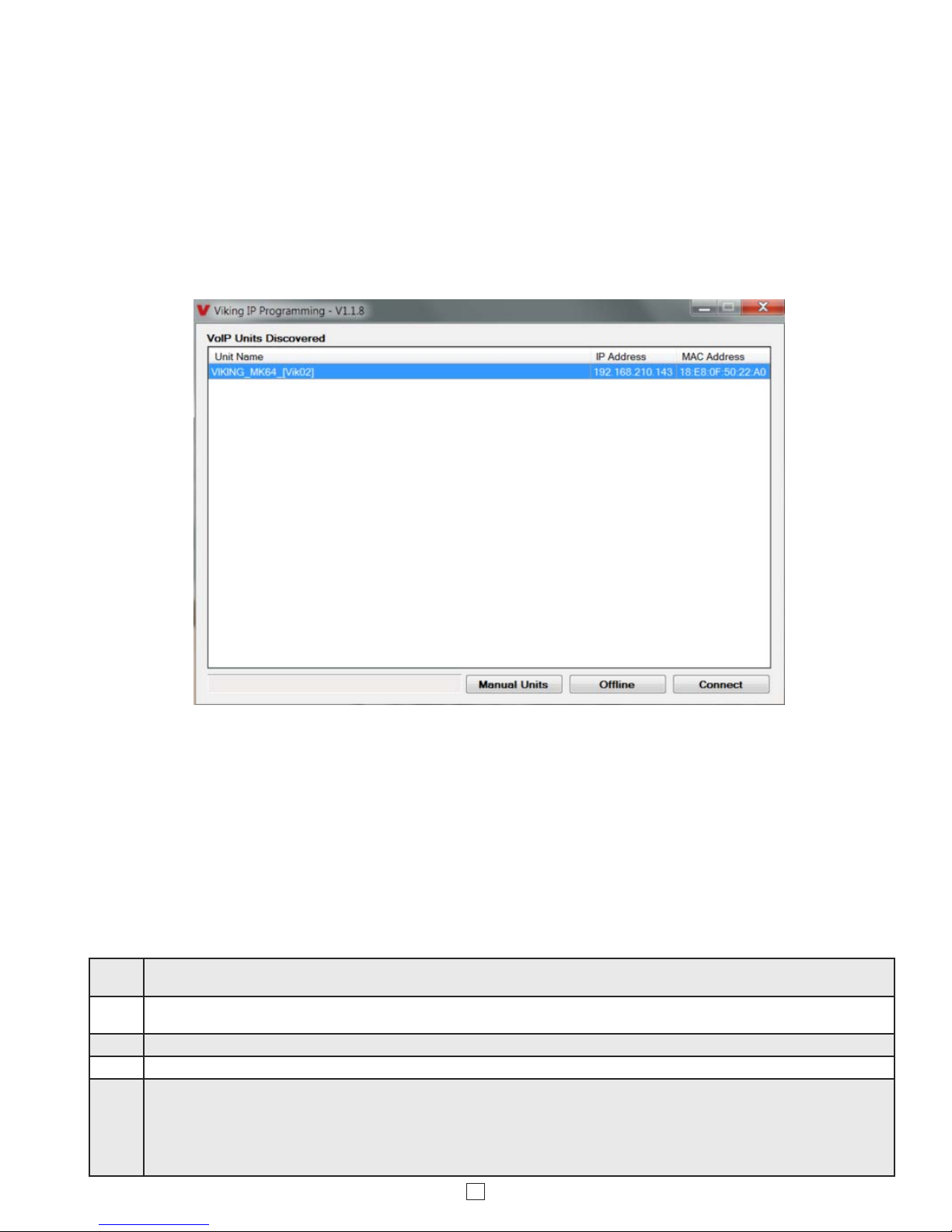
• Autoprovisioning via Viking programming software
• Built-in high efficiency 6 Watt class D amplifier
• SIP/Multicast: SIP page, SIP page and zoned multicast stream, zoned
multicast receive
• Support for access code to prevent unwanted SIP calls
• Line-level audio output for connecting to an external amplifier
• Network remote speaker volume control
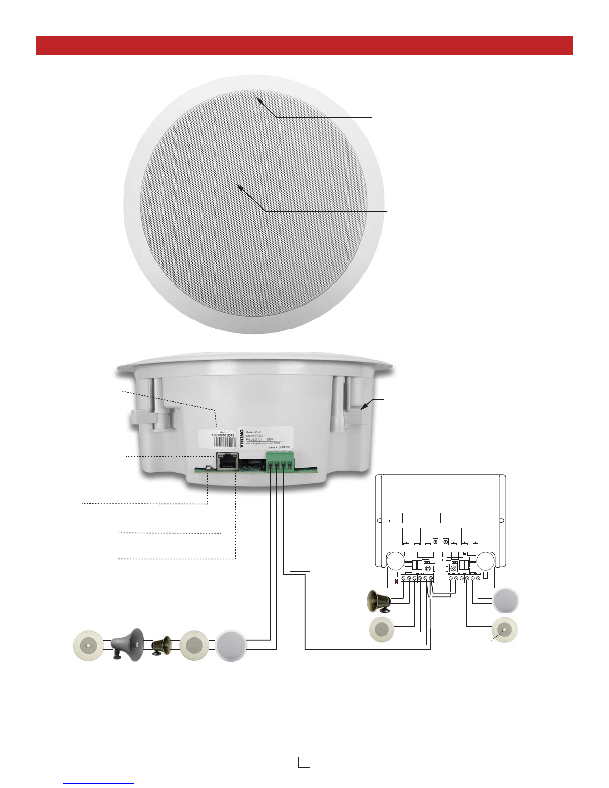
• Can drive up to 5 external analog speakers for greater coverage
• Mounting: Blind mounts into 9.5” hole, clearance requirement of 3.45”
(87.3mm) above 1/2” gypsum board ceiling
• Heavy duty back box protects speaker and circuitry from plenum dust
Power: PoE class 3 (<13 Watts)
Dimensions:
Overall: 11” x 11” x 4” (279mm x 279mm x 102mm)
Back box: 9.25” x 9.25” x 3.45” (235mm x 235mm x 88mm)
Shipping Weight: 5.0 lbs (2.27 kg)
Operating Temperature: -40°F to 140°F (-40° C to 60° C)
Humidity - Standard Products: 5% to 95% non-condensing
Audio Codecs: G711u, G722* and G711a*
Network Compliance: IEEE 802.3 af PoE, SIP 2.0 RFC3261,
100BASE-TX with auto cross over
Connections: (1) RJ45 10/100 Base-T, (1) 8 position terminal block
Maximum Output Level: 105 dB SPL @ 1M (with no additional Speakers
connected)
Amplifier: 6 Watt class D (capable of driving up to five additional 8
Ohm speakers connected in parallel)
*NOTE: The 40-IP does not support multicast paging using the G722 or G711a Codec.
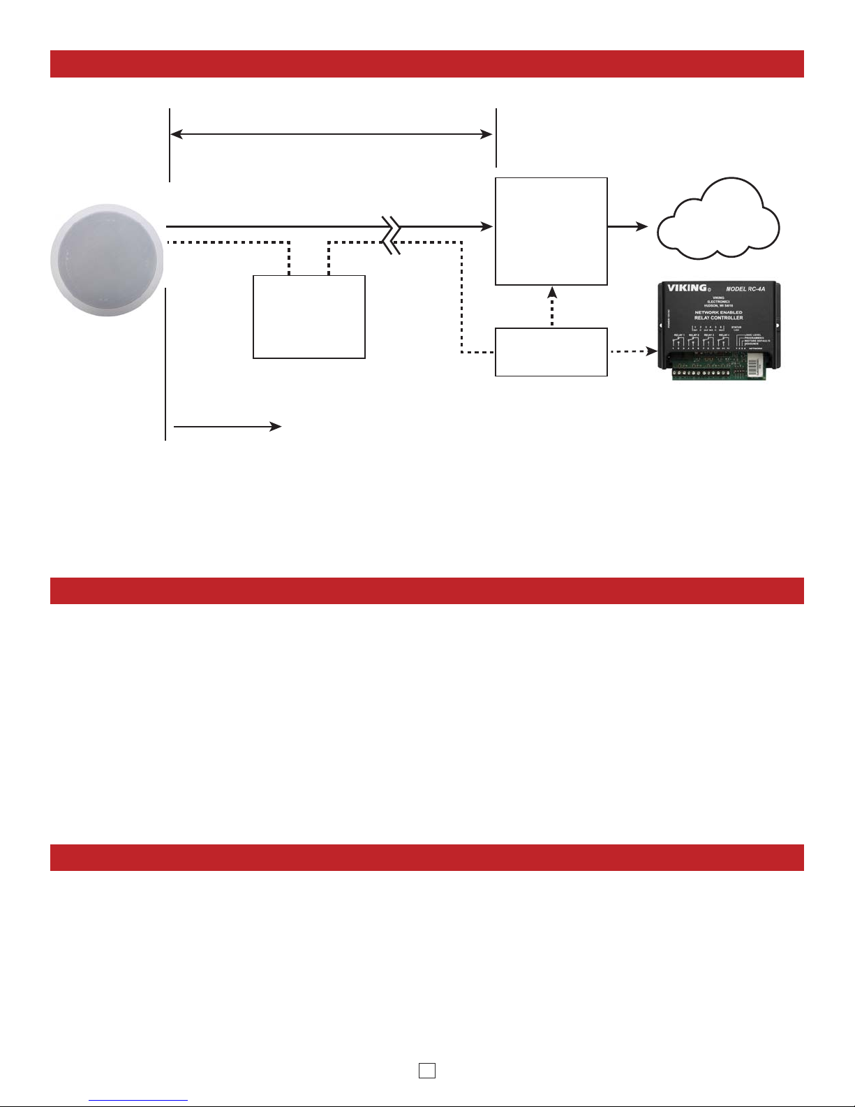
The Viking model 40-IP Ceiling/Wall Speaker enables SIP
endpoint paging and also allows for standard paging and
background music via multicast. The speaker easily connects
with a single CAT5/6 cable from your PoE switch. The night
bell feature is programmable for time of day and day of week
to enable loud ringing for after hour incoming calls. Its shallow
depth allows the speaker to be conveniently mounted in a
standard 2” x 4” stud wall or ceiling.
Line-level audio output connections are provided for
connecting to an external amplifier. A built-in 6 Watt class D
amplifier with speaker output connections are also provided
to directly drive additional analog speakers. The LED on the
40-IP can be programmed to light during paging.
• Amplified SIP endpoint or multicast IP paging for: schools, hospitals,
retail stores, office spaces, etc.
• Provide background music and sound masking
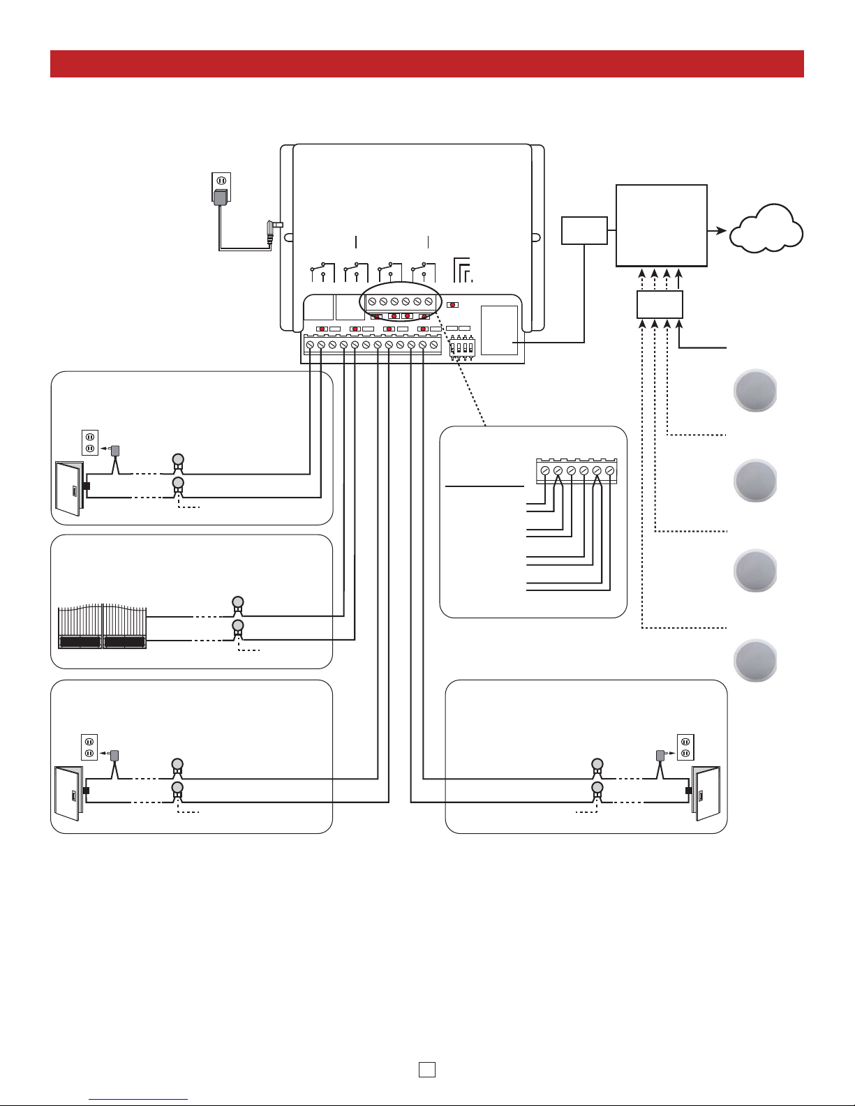
• Add programmable secure relay control with optional RC-4A see
DOD# 582
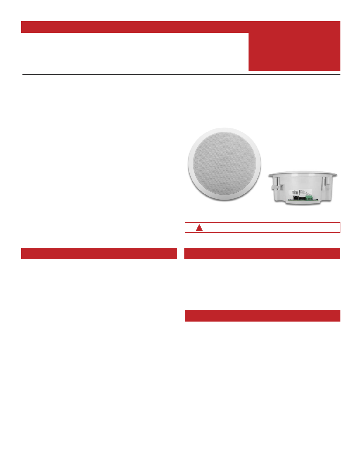
40-IP
SIP / Multicast
Ceiling Speaker
January 8, 2018
IP Ceiling Speaker for SIP Endpoint Paging or
Multicast Paging / Background Music
Applications
Installation requires a Network Administrator / IT Technician
!
Model
40-IP
(front view) (side view)
Features