Viking VSC 61 FY User manual

Table of Contents
•Preliminaries
•Introduction
•Vessel Operations
•Fuel System
•Propulsion System
•Electrical System
•Electrical Safety
•Bilge Pumps
•Heating / Cooling System
•Fire Emergency
•Corrosion Protection
•Subsystems
•Water System
•Sanitation System
•Vessel Care
•Addenda
•Service Numbers Directory
VSC
61 FY
Owner’s Manual

v1.0
Owner’s Manual
Vessel Operations - 4 Viking Sport Cruiser 61FY
••••••••••••••••••••••••••••••••••••••••••••••••••••••
The Publisher’s Statements on
page i
of this Owner’s Manual apply
to this chapter. Please read before
proceeding.
○○○○○○○○○○○○○○○○○○○○○○○○○○○○○○○○○○○○○○○○○○○○○○○○○○○○○○○○○○○○○○
Vessel Operations
This chapter provides an overview of vessel operations
and basic inspection and monitoring routines necessary
to safe and reliable boating.
Major Topics:
Vessel motive power 5
Pre-voyage inspection – engine room 6
Aft engine room checks 7
Pre-voyage inspection – Lazarette 9
Getting underway 10
Engine start 11
Salon helm switches and warnings 12
Bridge helm switches and warnings 13
Cruising 14
Engine controls 15
Using the trim tabs 16
Using the bow thruster 16
Anchoring (use of windlass) 17
At the end of the voyage 18
Hooking up to shore services 18
Leaving the vessel 20
Thru-hull fittings (drawing) 21
TABLE OF CONTENTS

v1.0
5 - Vessel Operations
Viking Sport Cruiser 61FY
Owner’s Manual
••••••••••••••••••••••••••••••••••••••••••••••••••••••
Vessel Motive Power
Before leaving the dock various checks of mechanical
equipment on the boat must be made to ensure the
safety of all aboard. Some of the checks also apply when
leaving an anchorage. On a boat you should never take
anything for granted.
Engine room checks should be done first, in case a
problem is found that requires your attention or marina
service that could delay your intended departure time.
Viking 61FY
is equipped with twin MAN D 2848 LE 403
V90°8-cylinder 4-stroke marine diesels. They feature
direct injection and turbochargers with intercooling and
a wastegate. Bore is 128 mm and stroke 142 mm (5.04
x 5.59 in) The governor is mechanically controlled, with
maximum revs of 2300. Power output is 800 brake
horsepower (bhp). When idling or under low load, half
the cylinders switch off. The wastegate gives improved
acceleration capability.
These engines have low fuel and oil consumption and
require minimal maintenance.
The engine and marine gear controls are Rexroth BJ system
with Type 240 control head Aand a BJ throttle servo motor
to operate the push/pull cables for the mechanical governor.
The clutches are solenoid operated, B. Engines drive a
Twin Disc marine gear, MG 5114A. Specs in the MAN
Fuel,
Lube & Coolant
manual require various brands of oil and
coolant. Sump capacity is 3.7-4.8 gal U.S. (18 L).
Both engines are equipped with 28 volt alternators. Once
the engines are switched on the alternators are triggered
to produce from 55 to 120 amps at 28 volts, depending
on engine revs.
B
A

v1.0
Owner’s Manual
Vessel Operations - 6 Viking Sport Cruiser 61FY
••••••••••••••••••••••••••••••••••••••••••••••••••••••
←
Pre-Voyage Inspection
– Engine Room
Enter the engine room via the cockpit hatch.
Check port and starboard Vetus strainers, S. Look through
each lid to ensure they are clear of weeds and debris. If
not, close seacock V; unscrew and remove the six bolts B
securing the top of the strainer. Remove debris completely
and replace the lid – ensure it is properly screwed down
tight. Open seacock V and check for leaks around the lid.
Next, check the forward engine room bilge, BP.4. Look for
traces of oil – if found, the source must be discovered and
corrected. If water level in the bilge is above the Rule-A-
Matic housing the pump is not switching on (check
breakers). Assuming bilge water is not excessively high,
test the the pump and switch by turning knurled knob K
to lift the float inside the cage. Pump should start and
remove water from the bilge until it sucks air. Hose M is a
manual pickup connected to the emergency manual bilge
pump in the aft cockpit.
Check the bilge and under both engines for oil or coolant
leaks. Walk aft inspecting engines for oily marks and stains
from coolant leakage.
Check coolant level in expansion recovery tank (if installed).
To check actual level, WHEN COLD, remove cap C. Level
should be 1/2inch below the internal screen, below the
filler cap seal. If not, coolant must be added. (Normally, it
will not go down very much, if it does you may have a
leak). Do not overfill header tank. Capacity is 96 litres.
Texaco Extended Life (ETX 6024) antifreeze mixed 40%
MINIMUM to potable water is one of the options in the MAN
booklet. NEVER use water ONLY.
Look at the gauge Eon top of fire extinguisher bottle. The
needle should be in center of the green area.
Check the oil level. It should be halfway between MAX and
MIN dipstick notches. If not, top it up, but DO NOT OVERFILL.
If overfilled, the connecting rods could rotate into the oil,
actually causing a lack of oil to critical engine parts, resulting
in severe engine damage. Top up with one of the oils listed
in the MAN booklet. Oil change capacity is about 7.7 U.S.
gallons. Change oil at 200 hours or yearly. Oil is the
lifeblood of an engine – NEVER delay an oil change.
Oil Fill
Dipstick
Do NOT
top up
with
fresh
water
only
Fwd
engine
room
BP.4
#2
manual
Check coolant level here
(if a bottle is installed), but
DO NOT top up here.
Aft
engine
room
Note:- Environmental laws prohibit fuel oil
contaminating waterways. Be responsible in
disposing of discarded fuel and oil. Inspect
for engine room oil leaks.
BP.5
S
V
M
S
K
K
C
E
B

v1.0
7 - Vessel Operations
Viking Sport Cruiser 61FY
Owner’s Manual
••••••••••••••••••••••••••••••••••••••••••••••••••••••
Aft engine room checks
At the stern, check the Twin Disc marine gear oil level.
Normally this should be checked when the oil is hot.
Dipstick level when hot,
2 minutes after the engine is
stopped,
is between high and low marks . DO NOT overfill.
One oil recommended is Shell Rotella-T SAE 30 or 40. Do
not use multigrade oil. Remove vent plug Dwith a wrench
to top up oil level.
Check propeller shaft and Tides self-aligning shaft seal.
A nitral lip seal prevents entry of seawater into the engine
room. Salt from the ocean is very corrosive and the seal
stops it. No water should be visible here. The black hoses
carry cooling water from the engines to lubricate the seals.
The hoses should be firmly attached and no leaks visible
when the engines are running.
It is essential that the valves
supplying cooling water to the tubes be open
.
The black disc at left C is a carrier kit containing a
replacement nitral lip seal in case one gets damaged or
leaks. Replacement can be done with the boat in the water.
Consult the Strong Seal documentation for instructions.
Graphite bonding brushes Bmake contact with the metal
shaft and protect propellers and thru-hull fittings from
corrosion. Wire Wleading from it connects to the bonding
system and external sacrificial zinc anodes. The shaft MUST
be free of dirt and seawater deposits under the brush.
Check Port and Starboard Separ fuel oil filters. Ensure that
the “clear bowl” at the filter base is indeed clear. The fuel
should be a clear amber color. A little water at the base is
okay unless you have a long voyage ahead. If the bowl is
not clear or shows excessive water, the filter needs to be
serviced – see Fuel System chapter for details on servicing
the filter, also look in the Separ filter Owner’s Manual.
Selection lever Lengages either filter to supply the engine.
Normally the vessel runs on one filter of each pair (enabling
the closed filter to be serviced if needed). For extensive
running at high speed it might be advisable to have the
selection lever in the center, thus drawing fuel from both
filters to avoid any chance of fuel starvation.
Water sensor Striggers a warning at the helm if collected
water reaches sensor level. If the alarm goes off the water
must be drained as soon as possible.
Aft engine room bilge pump, BP.5 This is under the last
hatch in the engine room floor, by the aft bulkhead. When
the boat is at rest and level there should be no bilge water
here but as the boat comes on plane bilge water can run
back. When water declines to just above the base of the
pump, pump will stop. It would pump only air if it did not
switch off.
cooling water
bonding
spare seal kit
brushes
dipstick
Separ filter pair
Select one filter for use by moving
lever Lall the way towards it. The
other filter is your spare.
In use
Spare
BP.5
D
B
C
W
L
S

v1.0
Owner’s Manual
Vessel Operations - 8 Viking Sport Cruiser 61FY
••••••••••••••••••••••••••••••••••••••••••••••••••••••
←
Aft engine room
checks, cont.
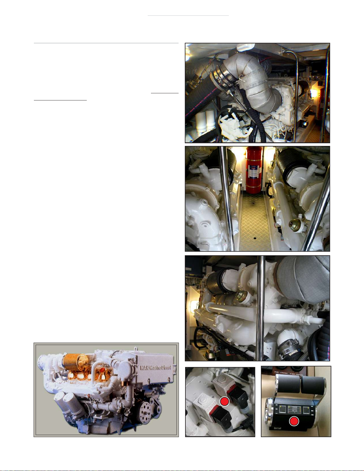
Keep the engine room clean,
this makes it easier to see
leaks, which indicate a prob-
lem that must be addressed.
There should be no oil on the
outside of or under the en-
gines. Use a funnel when top-
ping up the oil level. Do not
overfill. Keep the level a little
below the FULL mark. Overfill-
ing can damage the engine.
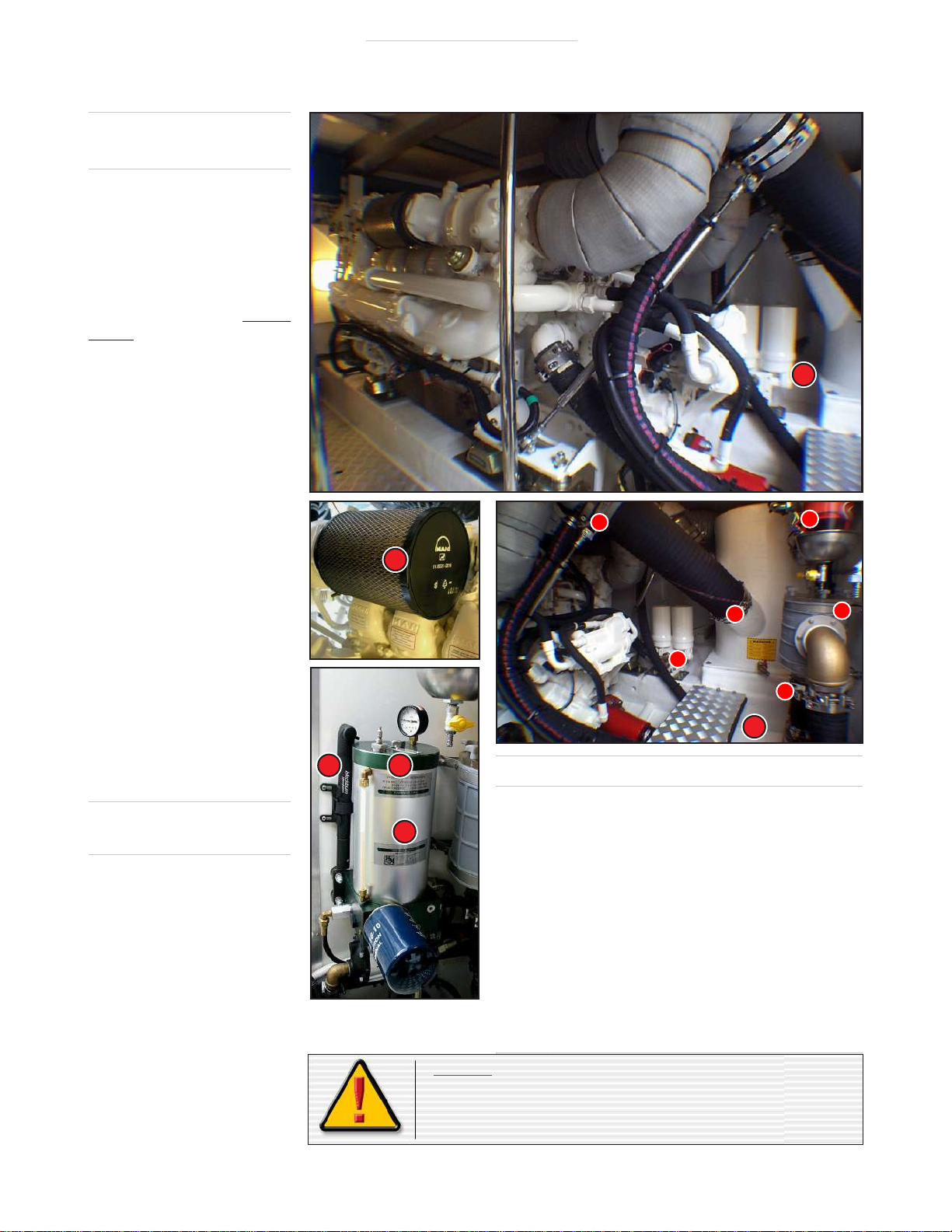
Check for leaks on all fittings
that have hose clamp attach-
ments, at the base of oil fil-
ters C, on the outside of the
Separ fuel filters, lids of raw
water strainers etc. Check the
outside of the engine air filters
M, look for oil on the outside
of them. This will indicate that
the filter must be replaced.
At least monthly open and
close the engine raw water in-
let valves V. On a long voy-
age, every two hours slow
down, don ear muffs and look
into the engine room for ob-
vious signs of leaks, fumes,
odor, smoke or a different or
excessive noise.
See propulsion chapter for
more information.
Power steering
reservoir, R
Check oil level in sight tube L.
Check for oil and air leaks. Air
pressure should be between 20
and 30 psi. If lower than 20 psi
use hand pump Hto increase
pressure to 30 psi. See the
Subsystems chapter for more
information.
Filter
C
C
C
C
C
C
Check
for
black
marks
here
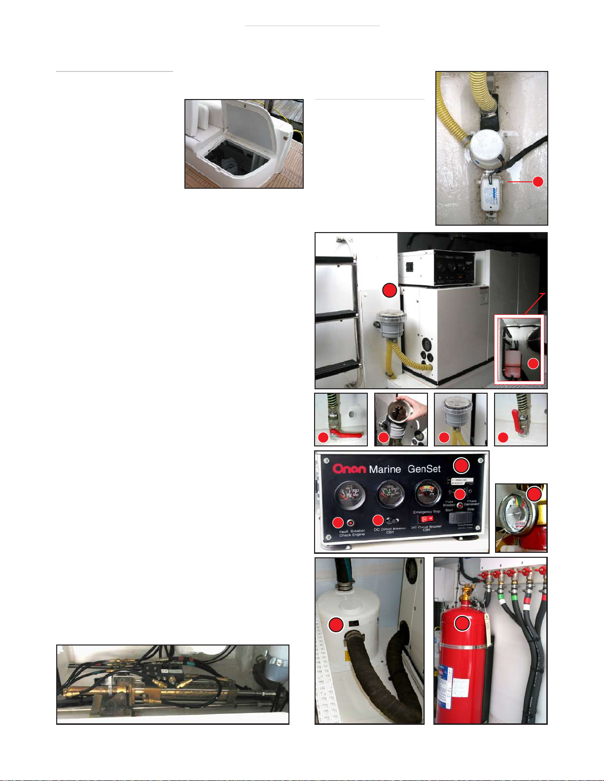
Engine water lift mufflers
Water lift mufflers are installed on all Viking boats. They
result in a very quiet running vessel, allowing normal
conversation when underway.
Inspect the white fibreglass for black marks, which may
indicate exhaust gas leakage caused by a loose hose
clamp.
This must be attended to
as deadly carbon mon-
oxide gas can seep through the vessel.
Use a SHORT 5-inch ratchet and the correct size socket
to see if the bolt in the clamp is loose. DO NOT USE
EXCESSIVE PRESSURE – the fibreglass piping can be
deformed resulting in a serious exhaust gas leak.
Warning:- Do not store loose or flammable materials,
equipment, or gear in the engine room. Objects must be
prevented from falling on the engines. Do not obstruct
entrance to engine room.
C
H
L
M
R
V→
↵

v1.0
9 - Vessel Operations
Viking Sport Cruiser 61FY
Owner’s Manual
••••••••••••••••••••••••••••••••••••••••••••••••••••••
BP.6
Pre-Voyage Inspection
– Lazarette
There is very important
equipment in the lazarette.
It must be checked before
a voyage. Lift off cushions
on bench for access.
Check bilge pump, BP.6. This is under the first floor panel
aft of the entrance ladder. Check operation of system by
lifting float with knurled knob A. Pump should start. After
30 seconds the high bilge level alarm should sound. If sys-
tem checks out, return float switch to normal with knob A.
If you intend to use the generator, check it next. First,
look through the transparent cover of the strainer D. Any
debris must be cleared:
1. Close the generator seawater thru-hull.
2. Remove strainer lid, and clear out all debris.
3. Replace the lid.
4. Open the thru-hull; check for leaks.
Check the generator coolant recovery bottle C(outboard
side of generator). If needed, top up with diesel truck an-
tifreeze – Zerex or Prestone with Alumaguard. Mix with
water, ratio depending on the vessel’s normal location.
Check the oil level, top up with SAE 30, 10W-30, or
15W-30, depending on climate (see Onan Owner’s Manual).
For convenience, the generator is usually started from
the salon main panel. But starting from the GenSet Panel,
K, enables you to check the instruments to monitor its
performance. After starting check that seawater discharge
out the exhaust is normal (aft stb). Note:- If any of the
GenSet breakers Bhave tripped it wil not start.
Check water lift muffler Wfor any sign of loose clamps or
leakage of exhaust gas (usually indicated by black marks).
Check the Sea-Fire extinguisher F to ensure it is fully
charged, J (on green). If it has discharged for some rea-
son this will be obvious by looking at the discharge head.
Examine the steering gear, ensure all is in order with no
oil leaks or loose parts, etc. Also be sure there is no stowed
gear that could move and foul the steering mechanism.
Bilge pump 6
Twist knurled knob Aand
hold for 30 seconds –
bilge pump should start to
run and high bilge alarm
should sound.
Pump is below first hatch
aft of the entrance ladder.
The generator seawater
pickup Gis below the next
hatch aft.
Manual
pump
pickup
MP.3
Oil changer
4
3
2
1
C
A
BB
B
Steering gear
W
F
J
K
↓
D

v1.0
Owner’s Manual
Vessel Operations - 10 Viking Sport Cruiser 61FY
••••••••••••••••••••••••••••••••••••••••••••••••••••••
Getting Underway
Go through the vessel closing all catches, cupboards, drawers, doors. be sure to lock the shower doors. Close and
secure all portholes and hatches. Store all loose equipment, lamps, ornaments etc. Open all blinds and curtains on
the salon deck. Have you enough fresh water, and
more
than enough fuel for the intended voyage? Is the anchor
safety strap in place? Have you checked the weather report and sea conditions? Binoculars and charts at the helm?
If all this is done it is now time to start the generator if it will be used underway.
Master battery switches
Turn on ENGINE START BATTERY switch E– the engine
batteries will now deliver power to start the engines.
Voltage on the meter should be about 28.4 V with the
battery charger ON. Engines will not start if voltage is below
23 volts. All the time the engines are running ENGINE START
BATTERY switch EMUST be on. When
not
running the
engines, switch it off for safety.
The master switches for both ENGINE START Eand AUXILIARY
BATTERY (i.e. house batteries) H output remotely through
a high amperage contactor/isolator in the lazarette, which
actually switches the power on or off.
There must be no
load on the circuits when activating the master switches
.
Any load will produce sparking and contact burning.
To start the generator
Before starting, conduct usual pre-voyage checks of fluid
levels and strainer.
1. Ensure
GENERATOR SWITCH
K(in laz.) is ON. Push right side
of GENERATOR button T for preheat. Hold for 10 seconds.
2. Push START button S; generator will start. When it does,
release
button.
Let it run a few minutes with no load. A red LED on the
switch will indicate the generator is on.
Note:- If it won’t start after holding in the button for 20 seconds,
let it go. Try again after 30 seconds minimum.
3. PUT OFF ALL AC SWITCHES.
4. Turn rotary power source selection switch P to off. SHORE
LINES 1&2lights stay lit until shore lines are unplugged.
5. Turn switch Pto GENERATOR G. Shore lines can be unplugged
and stowed at this point (lights 1 &2 will go out).
6. Check flow of cooling water discharge. Apply loads progres-
sively as required. Check that AC voltage is normal.
When switching back to shore power reverse the procedure, except
generator shut down is by pushing the STOP Tbutton.
Put off all AC switches before
changing power source
H
E
Generator switch
This ‘kill’ switch in the
lazarette switches current
from the dedicated
generator start battery.
S
Power source selector
G
1
2
P
E H
P
TS
K
Power source
As shown here, the vessel
is on shoreline 2 only and
the generator is running
(red switch light glowing).
ALL LOADS MUST BE OFF to start the
generator or to switch between Shore
Power and the Generator.

v1.0
11 - Vessel Operations
Viking Sport Cruiser 61FY
Owner’s Manual
••••••••••••••••••••••••••••••••••••••••••••••••••••••
Now it is time to start the engines
Your iinitial start must be from the Salon helm – thereafter, engines can
be restarted and stopped from the Bridge. Exept for keys, procedure is
the same for engine stop and start at either helm.
Mannesmann Rexroth controls – BJ system
This is a brief description of how to operate Rexroth en-
gine controls. See the
Marine Technique
operating instruc-
tion manual for more information. For other features and
details refer to the Propulsion chapter in this manual.
To engage controls:-
1. Put both Salon & Bridge control heads in the NEUTRAL detente
position.
2. Switch on BOTH ignition keys K. A loud alarm will sound and
the two red fault lights Fon the control head will glow brightly.
This is a self-test. The yellow POWER ON LEDs Pin each corner
will also glow.
3. Push COMMAND button C to acknowledge and cancel the alarm.
Both yellow COMMAND LEDs Lwill light up. A short BEEP tone
will be heard – indicating you have command at this station.
4. Start each engine individually by pushing briefly on the green
start buttons S. A warming up mode is available if required.
To transfer stations:-
5. Put both station control heads in NEUTRAL. Go to the new
station and push COMMAND button C. A beep will sound; the
yellow COMMAND LEDs Lwill glow.
6. You now have command at the new station, and both COMMAND
lights L stay lit.
7. To engage engine sync both P & S control levers must be
under command and ahead at cruise range (1000 rpm to full
revs). Push SYN/TROL button Y. The SYNCHRO LED H will light.
Port engine control is the master. To disengage push Y once.
If the control head is moved out of range, sync deactivates.
Final preparations – Disconnecting from shore services
Having switched off all breakers on the AC panel, some captains consider it good
practice to now switch off the SHORE SUPPORT breakers Qin the lazarette.
Make sure all 24 VDC breakers for household services are off then switch on AUXILIARY
BATTERY, H.
Disconnect both shore power cables. Wind them in with the Glend-
inning Cablemaster. Assign two crew, to ensure the cable doesn’t
snag or fall in the water. When cable is fully into its housing screw
down the lid to protect it from seawater.
Remove shore water pressure hose and stow safely. Replace cap
on vessel shore water inlet. Switch on fresh water pump O. Check
that you have pressure water coming out of the faucets
Check that all NAV lights Nare working. Chart plotter should have
all required courses entered ready to use. Navigation and electron-
ics equipment should be switched OFF while starting engines. O
N
K
S
P P
L
C
F H
Y
Note: The ‘trolling’
function is not used
Neutral Neutral
Q
A
H

v1.0
Owner’s Manual
Vessel Operations - 12 Viking Sport Cruiser 61FY
••••••••••••••••••••••••••••••••••••••••••••••••••••••
A.Windshield wiper #1
B.Windshield wiper #2
C.Windshield wiper #3
D.Windshield washers
E.Bilge pump #1
F.Bilge pump #2
G.Bilge pump #3
Salon helm switches
Engine warning lights
1.Engine coolant low
2.Engine preheat on
3.Water in fuel
4.Exhaust overheat
Note:-
At high revs low coolant or a worn or damaged impel-
ler will result in not enough cooling water going into
the heat exchanger, causing the engine to heat up.
H. Compass light
J. Navigation lights
K.Instrument lights
L. Electric window
M.Windshield demist
N. Horn
O.Anchor windlass
P.Windlass lock
C D E F GA B H J K L M
P
ON
Salon Helm Switches
Trim tab controls
32 41
Trim tabs
Located at stb, aft of control
levers.Push top edge to put
bow down; bottom edge to
raise bow.

v1.0
13 - Vessel Operations
Viking Sport Cruiser 61FY
Owner’s Manual
••••••••••••••••••••••••••••••••••••••••••••••••••••••
T. Compass light
U.Instrument lights
V.Anchor windlass up/down
Note
Switches shown are a
typical installation. Your
vessel may differ.
For a closer look at icons
and what they mean see
the Introduction, page 2.
Warning lights
1.Exhaust overheat
2.Engine coolant low
3.Bilge pump running
Q.Port tab up/down
R. Stb tab up/down
S.Horn
W.Anchor windlass lock
X.Helm lights
Y.Helm lights
Bridge helm switches
3
2
1 1
2
Trim tab controls
S TRQ
W
XVU Y
Bridge Helm Switches

v1.0
Owner’s Manual
Vessel Operations - 14 Viking Sport Cruiser 61FY
••••••••••••••••••••••••••••••••••••••••••••••••••••••
Cruising
If going out on the ocean on a long trip, inform the
Harbor Master or other responsible person of your
next port or anchorage and expected arrival. Check
the weather forecasts before leaving. On Florida’s
East Coast remember the south-to-north Gulf
Stream can be very rough if the wind blows oppo-
site to it. Upon leaving the dock, remove lines and
fenders and stow them safely. Switch off BOW
THRUSTER ENABLE in case it is accidentally activated.
Doors to the deck should be kept closed and
dogged down when underway. Watch your wake
near shore and marinas. If passing another boat in
a channel, let them know, keep your wake down as
you pass. Be aware of other boats and where you
are on the water. Observe Manatee areas. Keep a
sharp lookout for lobster traps, they often intrude
into buoyed channels
As in your car, you should AIM HIGH when steering,
scan from half way up to the horizon. This gives
you time to take evasive action if needed. Scan
the danger area OFTEN, between 10 and 2 o’clock.
Don’t slow down without looking behind. Again, as
in your car, a prime rule, YOU GO WHERE YOU LOOK
so LOOK WHERE YOU WANT TO GO. If you stare at
something, you’ll likely end up on top of it.
At sea, monitor the weather and adjust speed to
suit sea conditions. Observe speed limits. Good
seamen avoid extreme weather by heeding gale
and heavy thunderstorm warnings. If you have any
doubts about your position, particularly near shore,
slow down until you know where you are.
Check engine room,with ear muffs on, every two
hours or so on a long voyage, for smoke, leaks,
smell or excessive noise. Scan engine displays fre-
quently for deviation from normal. Once familiar
with the normal positions of all instruments you
can tell if potential problems are developing. Make
a note of them; attend to them promptly. Don’t let
service problems build up.
Monitor instruments often when underway
Engine management
Cruise at the engine revs you find best for comfort and
fuel economy. DO NOT RUN FULL REVS CONTINUOUSLY
– no more than 5 minutes in every hour is typically
recommended for maximum engine life.
At high speeds NEVER pull back the throttle quickly.
Reduce speed gradually to give a better ride for pas-
sengers, and to allow the following wake to reduce.
Coolant operating temperature should be 180-185°F, and
not exceed 190°F. If an impeller is worn or damaged
coolant temperature at high revs will go past 190°F and
trigger an alarm. Slow to below 2000 rpm and tempera-
ture will drop. Oil pressure depends on revs and grade of
oil. Get to know “normal” and monitor the gauges.

v1.0
15 - Vessel Operations
Viking Sport Cruiser 61FY
Owner’s Manual
••••••••••••••••••••••••••••••••••••••••••••••••••••••
Mannesmann Rexroth BJ
system controls
Changing stations
Changing stations is best done with the engines in neu-
tral. It can also be done with throttles at dead slow.
•At your old station, put BOTH the throttles at neutral or
revs at dead slow.
•Go to the new station and position BOTH the throttles
to match the throttle position of the old station.
•Push COMMAND pad CTWICE on the new station. A
short BEEP will be heard. Both lights 1 will light up at
new station and will stay lit, and go out at old station.
You now have command at the new station.
• There is a delay of a few seconds before control trans-
fers to the new station (which makes it possible for you
to do this on your own). It is advisable to have a look-
out at the old helm station to watch for any problems
and to steer if you are not on autopilot.
Engine synchronization
• To select sync. BOTH Port and Starboard throttle con-
trol levers must be in the command position and ahead,
and revs within the cruise range, 1,000 rpm to maxi-
mum.
• Push SYNCHRO pad S. PORT engine will now be in
command. Light 2will light up. Stb will be the slave,
only Port thottle needs to moved to alter revs on both
engines. Push button Sto deactivate, or to activate
again. If either thottle lever is moved out of range,
then sync will deactivate.
Changing direction suddenly
• To protect the marine gear and achieve the quickest
stop a delay is necessary between fast forward and
astern. This is set at the Princess factory to M.A.N specs,
10.5 seconds MAXIMUM. The delay interval can be ad-
justed, but decreasing the delay will NOT achieve a
quicker stop. DO NOT CHANGE THIS SETTING.
• Upon a Full-Speed Reversal (typically, an emergency)
the engine(s) decelerate but stay in gear until engine
speed drops to idle. A pause follows before throttling
to the commanded speed in the new desired direction
(pause is proportional to prior control head lever posi-
tion).
L1 L6
1
1
Both throttle levers must
be in the same position,
or in neutral to engage
sync.
2
CC
S S
Neutral “Fast Idle”
This feature is useful to increase revs for engine warm,
or to increase alternator output above idle. You must
be very careful, and BE SURE that gear is in NEUTRAL
before increasing idle rpm. To activate, with engines
running at normal idle:
1. Controls in NEUTRAL detente.
2. Depress & HOLD TRANSFER button C.
3. Move one or both control levers to AHEAD detente
position. A short double beep will be heard. Both
Lights 1will blink. Release transfer button C. The
transmission now remains in NEUTRAL. Further
movement of the control(s) will increase rpm to
desired level.
4. To reset controls to normal:- Return control lever to
NEUTRAL detente. Indicator lights 1will remain steady.
Note:-. If increased revs are required for warm up at
the dock, ensure that vessel is very securely tied up
to the the dock. While in this mode make sure that
no one can move the controls accidently.
Port engine Strb.engine
ALARM
CS
↑↑

v1.0
Owner’s Manual
Vessel Operations - 16 Viking Sport Cruiser 61FY
••••••••••••••••••••••••••••••••••••••••••••••••••••••
Trim tabs
•
Deploy tabs before climbing onto plane.
•
In heavy seas, keep the bow DOWN.
•
In following seas, keep the bow UP.
•
Running an inlet, use neutral tab position.
•
DO NOT overtrim at high speed; the bow
may dig in and cause the vessel to veer.
•
Do not reverse with tabs deployed.
•
In port, and docked, have tabs fully lifted.
Bow thruster control
Use bow thruster T in small bursts only. Long
bursts quickly build up momentum that can
slam the vessel into a dock. Watch out for
swimmers before using. Enable ON only when
in use.
Using the trim tabs
In port:– Tabs should be fully lifted in port, and at a dock.
In heavy seas:– Use tabs to keep bow down in heavy seas. In the
case of
following
heavy seas, tabs should be lifted.
Climbing onto plane:– Do not deploy tabs until you are about to
accelerate onto plane. During acceleration, add tabs in short bursts
as vessel comes onto plane. If tabs are overtrimmed the bow will
plow.
Cruising:– In normal seas, watch the bow wave as the vessel is
trimmed – at proper trim the bow wave and spray will move forward
and wake will be reduced. Do not overtrim – especially at speed!
Usually a power cruiser will plane most efficiently when the hull is
trimmed four degrees from horizontal, bow up, stern down. This
gives optimum handling characteristics and improves fuel efficiency.
The trim will change as fuel load changes and passengers move
around.
Coming off plane:– After the vessel has settled off plane, or when
operating at displacement speeds, lift the tabs.
Correcting a list:– If the port side is too high or too low, push the
control for PORT TRIM, up or down in small bursts to correct the situa-
tion. Confusingly, the PORT TRIM control operates the STARBOARD
trim tab and
vice versa
. The tab on the starboard side lifts the star-
board stern, which lowers the port bow to achieve the desired bal-
ance. Though tabs operate in reverse of what you might think, it works!
Look at the horizon when operating tabs to judge the amount of tab
required.
Using the bow thruster
The Side Power electric bow thruster is designed for intermittent
use. Viking Sport Cruisers recommend 20 seconds maximum of
continuous use. More than this and the motor will rapidly heat up
and the fuse may blow. In practical use, with twin propellers at the
bow, 20 seconds is more than you need. The main function of a
thruster is to assist leaving and coming up to a dock. Although you
can use the twin engines to move the stern in an arc, the thruster
enables you to move the bow in an arc as well and makes docking
much easier if the wind is off the dock.
The thruster tunnel is integrated with the hull to ensure the best
possible waterflow for the thruster and to avoid turbulence and cavi-
tation.
The thruster is supplied with 24 V DC power from the engine batter-
ies, and with the engines running full voltage is available. For safety
(in case accidentally touched) it is important to “enable” the thruster
only when it is about to be used. When not in use it should NOT be
enabled (i.e. OFF).
Push both together to enable
Bow DOWN
PS
T
Bow UP

v1.0
17 - Vessel Operations
Viking Sport Cruiser 61FY
Owner’s Manual
••••••••••••••••••••••••••••••••••••••••••••••••••••••
Using the Lewmar windlass
The master WINDLASS switch B (on Salon DC panel) should
normally be off until you are about ready to anchor. If pos-
sible drop and retrieve anchor with the help of a crew
member on the bow who can view the situation better
than you at the helm (especially the Salon helm). Look at
your chart to see if it is a designated and safe anchorage
and the bottom will hold. NEVER anchor over a coral reef
– you could face a hefty fine. It is sometimes better to
temporarily drop an anchor then take your dinghy to find
a protected spot inside an inlet, then take the vessel to it.
To anchor
Switch on WINDLASS master B. The green LED will glow.
Remove the anchor bridle C if installed. Release chain
stopper. Ensure anchor is clear to lower. Come up to the
anchorage, into the wind if possible. Watch for swimmers.
Ensure other vessels have room to anchor, and you have
room to swing. Be aware of water depth and tidal changes.
Stop the vessel. When ready, hold down spring-loaded
switch lock Dto permit use of windlass rocker E,then
push the top of rocker switch E to drop the chain.
Momentarily go astern as the anchor drops, or let the
wind carry you back. Pay out chain to about 3 times water
depth. When you let go of lock Dit springs back to prevent
switch Efrom moving.
When the vessel stops and it appears to be holding, give
a short kick astern to set the anchor. Look at landmarks
to see if the vessel stays in place. If not, you must reset
the anchor. Check the depth finder and set it to ANCHOR
WATCH mode. Drop the chain stopper Sonto the chain to
take strain off the windlass. Fit anchor bridle Cif provided.
Switch off WINDLASS master B. Ensure the vessel is not
swinging into another boat or into shallow water.
To weigh anchor
Remove anchor bridle Cif fitted. Start the engines. Switch
on WINDLASS master B. Enable bow thruster. Release the
anchor chain stopper.
Depress lock Dand hold it down. Idle up to the anchor
position, raising the chain as you do with switch E. When
you are right over the anchor it should let go; if not, nudge
the vessel ahead to get it to release. The thruster may be
required, depending on the wind.
When the anchor is home, release Dto lock the windlass
rocker E. Now lock the chain in place with the chain stopper.
Fit anchor bridle if provided. Switch off WINDLASS master B.
If the anchor or chain need washing attach a hose to faucet
Fin the anchor locker. There is a remote control Rin this
deck hatch for windlass UP and DOWN if required.
For more information see the Lewmar owner’s manual.
Anchor restraints
The type of anchor
restraint (bridle Cor chain
stopper S) depends on
the type of anchor used.
UP
DOWN
Chain stopper
Anchor
bridle
Note:- There is an 120 amp resetable circuit breaker
for the windlass inside the DC distribution cabinet
in the lazarette. If it trips through overload switch
off master windlass enabler B. Wait, then put it on
again. This will reset this breaker. Anchor may be
lodged on a rock or fouled in heavy weed. Before
trying again, pay some chain out. Let the vessel
move to a different angle, move to over the anchor,
and see if if the anchor can now be raised.
Switch lock, D
Hold down switch lock D
to permit the windlass
rocker switch Eto move.
B
C
FR
E
↓
↑
S
→
D

v1.0
Owner’s Manual
Vessel Operations - 18 Viking Sport Cruiser 61FY
••••••••••••••••••••••••••••••••••••••••••••••••••••••
Isolation transformer
There is an identical transformer for Shore 1
and Shore 2. (Optional IsoBoost 50 shown.)
At the End of the Voyage
It is better to operate the vessel from the bridge when entering or
leaving a marina and docking. If there is no current, dock into the wind.
If there is a strong current, dock into the current.
Slow down to reduce wake before you approach the harbor. Have the
crew position fenders, and make all lines ready.
Enable docking equipment:– Fully brief your crew on docking procedure.
Switch on HIGH LOAD ISOLATION Cto permit enabling of the bow thruster
– the green pilot light will glow. Enable the thruster itself just before
use (push the two ON buttons). If you need them, switch on SNUB
WINCHES breaker B– red and green (port & stb) pilot lights will glow
(no glow indicates a fault). Using the bow thruster, and a line ashore
attached to a bollard, the vessel can be snugged up to the dock easily.
Idle engines for 5 minutes:– If engines are shut down abruptly the oil
film the turbochargers ride on is lost, resulting in excessive bearing
wear. Do not rev engines during shutdown.
Shut down:– Switch off engines. Switch off snubbing winches. Switch
off bow thruster and HIGH LOAD ISOLATION switch C. Once docked, check
position of fenders, attach more if necessary, and tie the vessel securely
in a fashion appropriate to the type of dock. At a fixed dock, if possible,
it is better to cross-tie the vessel.
Shore power
If two 50 A shore power plugs are available, run out both shore power
cables D and plug them in. DO NOT let the cables fall in the water. The
electrical field can injure swimmers. It also causes corrosion of fittings
on your vessel and others nearby.
There are two sets of 240 volt hi-amp breakers Fin the lazarette. If
these have been shut off, as some captains prefer, they must now be
switched on. One set protects power input from shore; the other
protects output from the isolation transformer.
If only one shore plug is available either cable can be used – however,
ONLY 50 amps will be available for ALL electrical needs. In this case
power must be managed prudently to cut down load. For example, if all
A/C units are on they draw 40 amps; with one cable, only two A/C units
could be used. Restrict all other heavy loads. Watch the ammeter as
load is applied and do not exceed 47 amps.
To switch over from generator to shore power, do this:-
1. Switch off ALL AC switches (load) on the main panel.
2. Turn power selector switch P to OFF (see opposite page).
3. Let generator run with no load for at least 5 minutes to cool.
4. Switch off GENERATOR CONTROL start/stop S(opposite page).
Dock voltage should be 240 VAC. It may be low – but whatever it is
that is what standard isolation transformers deliver. However, the op-
tional Charles Iso-Boost 50 isolation transformers E, if installed, correct
input voltage between 175 & 210 AC, increasing volts by up to 15%.
Note that the AC busbar is split to allow input power to supply both
120 & 240V breakers.
Snubber control
Crew should know
where this foot switch
is and how to use it (or
not).
Shore 1
Shore 2
Port
Glendinning
cable bin
Star-
board
Lights show if switch is on
ON
B
C
D
A
E
D
W
ON
Shore 1 Shore 2
E
F F

v1.0
19 - Vessel Operations
Viking Sport Cruiser 61FY
Owner’s Manual
••••••••••••••••••••••••••••••••••••••••••••••••••••••
Engaging shore power
With two shore power lines
connected and shore power
breakers F (opposite page)
on, both green POWER AVAIL-
ABLE lights will be lit. If only
one shore line is plugged in
just one green POWER AVAIL-
ABLE light will be on.
Ensure again that all AC
breakers are off. Turn power
selector switch Pto SHORE
POWER. Voltmeters will reg-
ister voltage. With switch V
on DOMESTIC, voltage on
meter Vshould be 120. With switch Von AIRCON, voltage
should be 240. Because all the AC breakers are off amme-
ter Twill show zero amps.
Switch on the BATTERY CHARGERS K.
Switch on the DC LIGHTING M.
On the DC panel, check Engine Uand House Y DC volt-
ages; it should be about 28.0 volts. Apply loads as needed.
Start AIRCON PUMP L; activate A/C units (see A/C chapter).
When the engine room is cooler, switch OFF ENGINE START
battery switch X on the DC panel.
Shore water
Break out the fresh water hose and connect it to the shore
water supply. Hose should be FDA approved. The organic
plasticizer in some hoses, when left in the sun, makes
water taste sweet and maves it foam. Connect hose to
fitting Wan previous page, and to dock fresh water faucet.
When the hose is connected, switch off the FRESH WATER
PUMP 1on the 24 V panel. Ensure SHOWER DISCHARGE
PUMP 2is ON. Switch on hot water tank heater 3.
Water Quality:–It is prudent to filter all water coming
aboard. Install a good filter on the dock water faucet. It
should trap dirt and rust and have a charcoal element.
Instruct guests about Salon door
The Salon door has an automatic brake to prevent slam-
ming in a seaway. The chrome door handle Hnormally
points south. To release the brake and open/close the
door, turn the handle Hfrom pointing south to pointing
southwest, then pull/push the door. When you let go of
the handle it springs back to south and engages the brake.
Turn knob Kto lock / unlock the door. The silver tip shows
when unlocked.
V
T
V
P
S
K
U
X
240 V 120 V
Y
1
2
3
M
L
door locked
door un-
locked
V
V
T
H
K
K
P
R
S
Door mechanism
Turn to release; then pull to open.
➠

v1.0
Owner’s Manual
Vessel Operations - 20 Viking Sport Cruiser 61FY
••••••••••••••••••••••••••••••••••••••••••••••••••••••
Leaving the Vessel
When leaving the vessel, its safety is of prime concern. If
you plan on being away for an extended period, as many
as possible thru-hulls should be closed.
However, a record must be kept to ensure they are all
opened again before the vessel is put back in service. Put
a prominent notice on the helm to clearly identify what is
turned off, and inform the marina where the vessel is kept.
If the air conditioning is to be left running to reduce hu-
midity someone should check it daily in case a strainer
becomes blocked.
Mix and stir up a bucket of warm water and dishwasher
detergent, such as Cascade. Pour some down each sink
and shower, make sure it is pumped overboard from the
grey water sumps. Have the holding tank pumped out. To
control odor, pour a VacuFlush brand cleaner into each
toilet and flush while pumpout is running. Use of anything
other than a VacuFlush cleaner may cause damage to lines
and void your warranty. Ensure the VacuFlush toilets switch
is off.
Other items:
•Check all bilge pumps for operation. Empty all bilges
of free standing water. Use the emergency bilge pump
to completely empty the bilges.
•Turn off all switches not required to be left on.
•Ice makers should be turned off and emptied if left for
more than two weeks. The ice will become stale and
unpalatable. Fresh ice cubes can be made very quickly
and easily.
•Ensure the AC shore power cable cannot fall in the
water. It must be securely plugged in, and turned to
lock it in the socket.
•The shore water hose should be removed and stored.
•Close all curtains and blinds.
•Fit all covers on bridge helm and seats.
•Fit windshield covers.
•Make sure all outside entrance doors and escape
hatches are locked on the inside.
•If it is not a floating dock make provision when tying
the vessel for the tide rise and fall.
Whenever the vessel is left
unattended: Disconnect Shore
Water Supply and switch off Hot
Water Heater.

v1.0
21 - Vessel Operations
Viking Sport Cruiser 61FY
Owner’s Manual
••••••••••••••••••••••••••••••••••••••••••••••••••••••
Thru-hull Fittings
This drawing shows the location of thru-hull fittings on
the VSC 61Motor Yacht. These need to be well known
in event of an emergency. Shut off thru-hull valves if
leaving the vessel unattended, but make sure your
marina knows their status and location.
The holding tank overboard discharge must be kept
closed and opened only while discharging overboard
at sea. After discharge, close it immediately.
It is essential to “work” all thru-hull valves at least
monthly, preferably every two weeks. A regular open
and close cycle will keep them operating freely and
avoid future problems of seizing.
A-Holding tank overboard discharge
B-A/C seawater pickup
C-Depth log
D-Speed log
E-Raw water pickup, port engine
F-Raw water pickup. stb engine
G-Generator cooling water pickup
Hull-side underwater fittings
1(stb) - Generator Discharge
It’s a good idea to work the thru-
hull valves off and on every two
weeks so they won’t stiffen up.
→
1
B
CD
EF
G
A
Other manuals for VSC 61 FY
4
Table of contents
Other Viking Toy manuals
Popular Toy manuals by other brands

Eduard
Eduard CM.170 Magister S.A. quick start guide

Glow Bricks
Glow Bricks HarryPotter 4 Privet Drive Lego 75968 installation guide

educo
educo 523300 instructions

Smoby
Smoby BN Balneo Bath Assembly instructions

HobbyZone
HobbyZone AeroScout S RTF quick start guide

VMI
VMI Micro CAP 232 Assembly instructions