Vimar ELVOX 46264.001.01 User manual

Manuale utente - User Manual - Manuel de l'utilisateur
Bedienungsanleitung - Manual de usuario - Manual do utilizador
Εγχειρίδιο χρήστη
46264.001.01
Extender Ethernet PoE
PoE Ethernet Extender
Extender Ethernet PoE
Ethernet Extender PoE
Repetidor Ethernet PoE
Amplificador Ethernet PoE
Extender Ethernet PoE
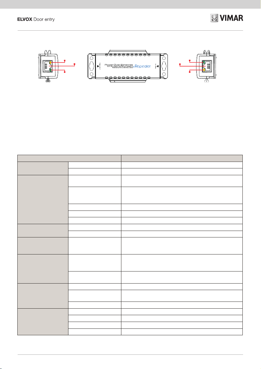
Right side
Left side Top view
PoE OUT PoE IN
PoE
Data PoE
Data
2
46264.001.01
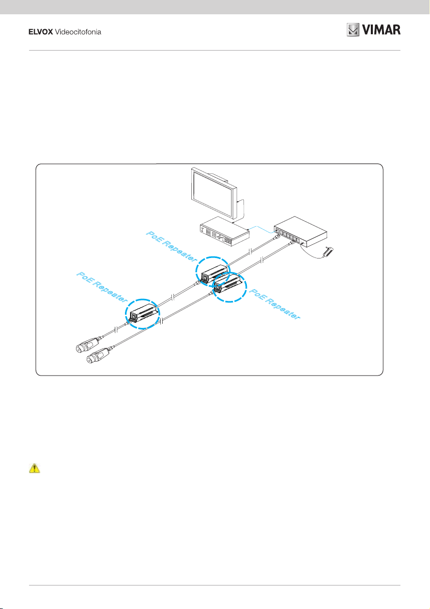
IP camera
LCD
Diaplay
NVR
IP camera
PoE Switch
PoERepeaterPoERepeater
PoERepeater
Cat5e/6
Cat5e/6
Extender Ethernet PoE
L’Extender Ethernet PoE 46264.001.01 permette la comunicazione e l’alimentazione di dispositivi PoE nei casi in cui la distanza
tra PSE (Power Sourcing Equipment) e PD (Powered Device) risulti maggiore di 100m.
Il prodotto supporta gli standard IEEE802.3u, 100Base-TX e IEEE802.3 af/at; può essere collegato in cascata ad altri extender
purché la distanza da extender ad extender non superi i 100m. Supporta la modalità di trasmissione full duplex a 100 Mbps con
un’ecace protezione contro scariche elettrostatiche (ESD) e sovratensioni transitorie (TOV). Il dispositivo, inoltre appartiene alla
classe di protezione IP40.
Caratteristiche
•
Ogni unità può ripetere ed estendere segnale ed alimentazione no a 100m e, in connessione a cascata, no a 400m.
•
Supporta gli standard IEEE 802.3u,100Base-TX e IEEE 802.3af/at.
•
Il dispositivo non introduce ritardo nella trasmissione del segnale Ethernet: funziona in tempo reale.
•
Protezione contro scariche elettromagnetiche e sovratensioni transitorie.
•
Connessione Plug and play.
Avvisi
1) Si consiglia di usare un cavo cat5e/6 per ottenere la distanza di trasmissione massima.
2) Accertarsi che la direzione di trasmissione PoE sia corretta.
Schema di connessione:
Materiale fornito:
Prima di procedere all‘installazione, vericare la presenza dei seguenti elementi e, se mancano, rivolgersi al rivenditore.
•
1 Ripetitore Ethernet PoE
•
1 Manuale utente

3
46264.001.01
Schema pannello
Nella vista superiore “PoE IN” e “PoE OUT” indicano la direzione di trasmissione PoE.
Sulle porte Ethernet il LED giallo indica lo stato dell'alimentazione PoE, il LED verde indica lo stato della connessione dati. L’aspet-
to dei LED varia a seconda dello stato:
• LED verde accesso sso: la connessione dati è attiva.
• LED verde spento: assenza di connessione dati.
• LED verde lampeggiante: connessione e trasmissione dati attive.
Right side
Left side Top view
PoE OUT PoE IN
PoE
Data PoE
Data
Lato sinistro Vista
superiore
Lato destro
Speciche
ArticoloDescrizione
Alimentazione Alimentazione PoE
Consumo < 3 Watt
Porta di rete
Porta PoE IN: 100Mbps, Porta di ingresso PoE
PoE OUT: 100Mbps, Porta di uscita PoE
Distanza trasmissione
Max: 400m
(Fare riferimento rispettivamente agli schemi I e II per valutare
distanza di trasmissione e potenza disponibile)
Cavo Cat5e/6
Standard PoE Supporta gli standard IEEE802.3af, IEEE802.3at
Alimentazione PoE Mid-span ed End-span
Scambio Ethernet Standard IEEE802.3u 100BASE-TX
Ritardo < 20us
Stato Spie LED
Porta IN PoE e porta OUT PoE:
Il LED giallo indica lo stato dell’alimentazione PoE;
il LED verde indica lo stato della trasmissione Ethernet.
Protezione
Scariche elettrostatiche
(ESD)
Livello III 1a scarica di contatto
Livello III 1a scarica in aria
Conforme a: IEC61000-4-2
Protezione contro le sovra-
tensioni transitorie
Livello III Conforme a: IEC61000-4-5
Ambiente
Temperatura di esercizio -10°C ~ 55°C
Temperatura di immagazzi-
namento
-40°C ~ 85°C
Umidità 0 ~ 95%
Caratteristiche mecca-
niche
Dimensioni (L×P×H) 113mm × 45,5mm × 29mm
Materiale ABS
Colore Nero
Peso (lordo) 58g
Le speciche del prodotto sono soggette a modiche senza preavviso.

4
46264.001.01
Relazione distanza di trasmissione e potenza disponibile
Schema I
Schema II
100m 200m
PoE Switch
260m
15W
10.9W 4.2 W 2.91W
0m 400m
100m 200m
P o E+ S w i t c h
300m
30W
20.86W 16.03W 10.26W
0m 400m
7.5W
I valori di potenza indicati presuppongono che:
-
nel caso di switch PoE+ sia rispettato il PB (Power Budget) di 30W su porta PoE+.
-
nel caso di switch PoE sia rispettato il PB (Power Budget) di 15W su porta PoE.
Installazione
a. Montaggio a parete b. Possibilità di innesto
I valori di potenza riportati indicano la minima potenza disponibile utilizzando switch PoE+ ovvero switch com-
patibili con standard IEEE802.3at.
I valori di potenza riportati indicano la minima potenza disponibile utilizzando switch PoE ovvero switch compa-
tibili con standard IEEE802.3af.

5
46264.001.01
Prima Attivazione
Eseguire la procedura di installazione descritta di seguito:
1) Prima dell’installazione, disinserire l’alimentazione elettrica di tutti i dispositivi connessi, onde evitare danni al dispositivo.
2) Controllare se il cavo Ethernet e gli altri cavi sono connessi correttamente.
3) Collegare la porta PoE IN del ripetitore Ethernet PoE, con la porta PoE dello switch, tramite un cavo Ethernet.
4) Collegare la porta PoE OUT del ripetitore Ethernet POE, con generico PD, tramite un cavo Ethernet.
5) Assicurarsi che i singoli dispositivi siano integri, vericare che l’installazione sia stata eseguita correttamente e che tutte le
connessioni siano adabili, quindi procedere con l’alimentazione del sistema.
6) Accertarsi che la rete e l’alimentazione PoE siano funzionanti.
Risoluzione dei problemi
Se si riscontrano problemi durante l'installazione, seguire questi passaggi:
•
Accertarsi di aver seguito le istruzioni di installazione del dispositivo.
•
Controllare che il cablaggio dei connettori RJ45 sia conforme alle norme industriali EIA/TIA 568A o 568B.
•
La distanza di trasmissione dipende dalla sorgente del segnale e dalla qualità del cavo. Non superare la distanza massima di
trasmissione.
•
Sostituire il dispositivo in avaria con uno che funzioni correttamente per vericare se il dispositivo è realmente guasto.
•
Se il problema persiste, contattare il rivenditore.
Regole di installazione
L’installazione deve essere eettuata da personale qualicato con l’osservanza delle disposizioni regolanti l’installazione del materiale
elettrico in vigore nel paese dove i prodotti sono installati.
Garantire delle distanze minime attorno all’apparecchio in modo che vi sia una suciente ventilazione.
L’apparecchio non deve essere sottoposto a stillicidio o a spruzzi d’acqua.
Conformità normativa
Direttiva EMC
Norme EN 60950-1, EN 55032, EN 55035
Il manuale istruzioni è scaricabile dal sito www.vimar.com
RAEE - Informazione agli utilizzatori
Il simbolo del cassonetto barrato riportato sull’apparecchiatura o sulla sua confezione indica che il prodotto alla ne della
propria vita utile deve essere raccolto separatamente dagli altri riuti. L’utente dovrà, pertanto, conferire l’apparecchiatura
giunta a ne vita agli idonei centri comunali di raccolta dierenziata dei riuti elettrotecnici ed elettronici. In alternativa alla
gestione autonoma, è possibile consegnare gratuitamente l’apparecchiatura che si desidera smaltire al distributore, al momento
dell’acquisto di una nuova apparecchiatura di tipo equivalente. Presso i distributori di prodotti elettronici con supercie di vendita
di almeno 400 m2 è inoltre possibile consegnare gratuitamente, senza obbligo di acquisto, i prodotti elettronici da smaltire con
dimensioni inferiori a 25 cm. L’adeguata raccolta dierenziata per l’avvio successivo dell’apparecchiatura dismessa al riciclaggio,
al trattamento e allo smaltimento ambientalmente compatibile contribuisce ad evitare possibili eetti negativi sull’ambiente e sulla
salute e favorisce il reimpiego e/o riciclo dei materiali di cui è composta l’apparecchiatura.
6
46264.001.01
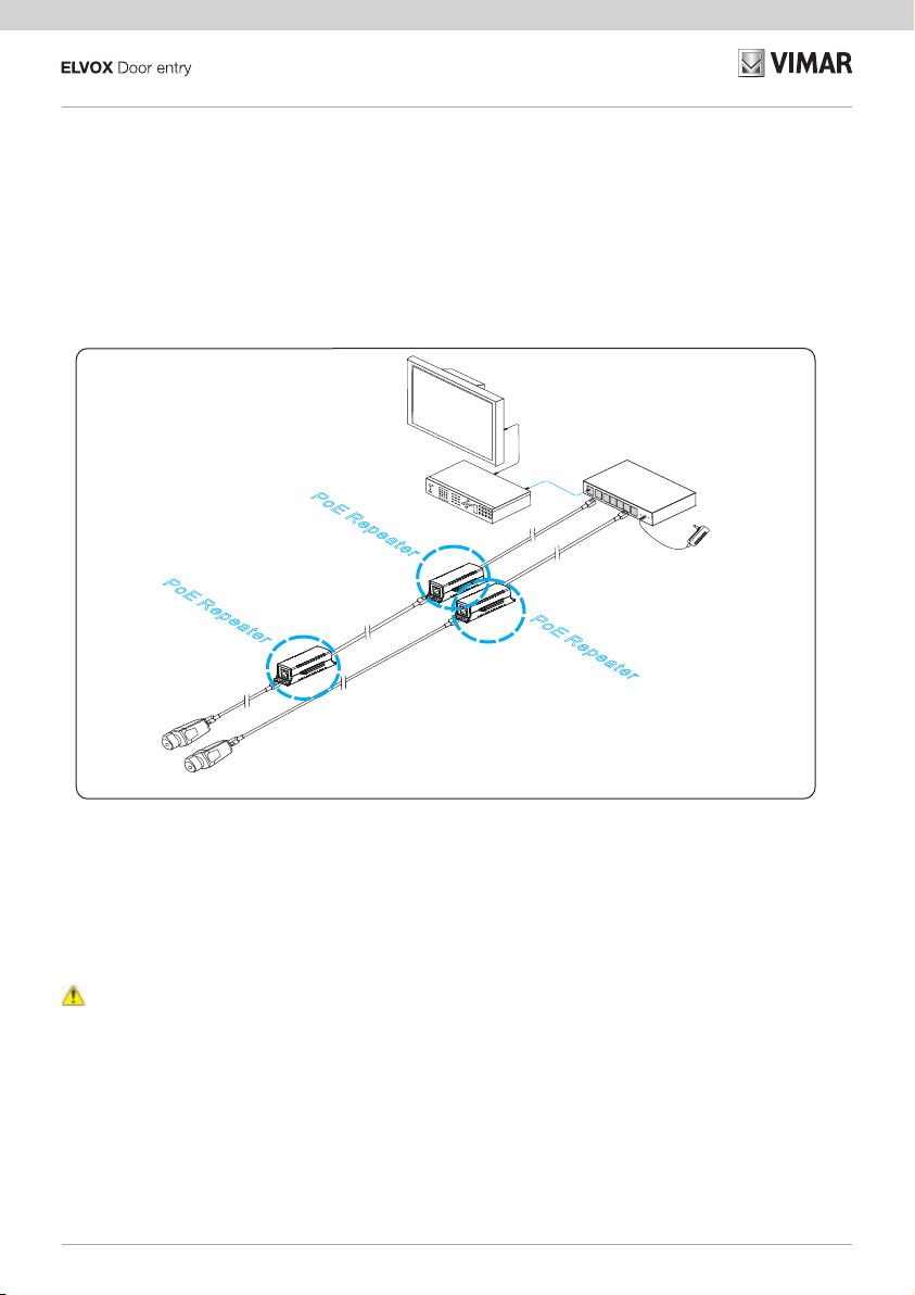
IP camera
LCD
Diaplay
NVR
IP camera
PoE Switch
PoERepeaterPoERepeater
PoERepeater
Cat5e/6
Cat5e/6
PoE Ethernet Extender
The PoE Ethernet Extender 46264.001.01 is used for the communication and power supply of PoE devices if the distance between
the PSE (Power Sourcing Equipment) and the PD (Powered Device) is greater than 100 m.
The product supports standards IEEE802.3u, 100Base-TX and IEEE802.3 af/at; it can be connected in cascade with other ex-
tenders provided the distance between one extender and another is not more than 100 m. It supports full duplex transmission at
100 Mbps with eective protection against electrostatic discharge (ESD) and temporary overvoltage (TOV). The device also has
protection rating IP40.
Characteristics
•
Each unit can repeat and extend both signal and power supply up to 100 m and, when connected in cascade, up to 400 m.
•
It supports standards IEEE 802.3u,100Base-TX and IEEE 802.3af/at.
•
The device creates no delay in the Ethernet signal transmission: it works in real time.
•
Protection against electromagnetic discharge and temporary overvoltage.
•
Plug and play connection.
Warnings
1) Use a cat 5e/6 cable to obtain the maximum transmission distance.
2) Ensure that the PoE transmission direction is correct.
Wiring diagram:
Material supplied:
Before installation, check that the following components are present; contact your retailer for any missing components.
•
1 PoE Ethernet repeater
•
1 User manual
7
46264.001.01
Panel diagram
In the upper view, “PoE IN” and “PoE OUT” indicate the PoE transmission direction.
On the Ethernet ports the yellow LED indicates the PoE power state, the green LED indicates the data connection state.
The appearance of the LEDs varies according to the state:
• Green LED on steady: data connection active.
• Green LED o: no data connection.
• Green LED ashing: data connection and transmission active.
Right side
Left side Top view
PoE OUT PoE IN
PoE
Data PoE
Data
Left-hand
side
Upper view Right-hand
side
Specications
ArticleDescription
Power supply Power supply PoE
Current consumption < 3 Watt
Network port
Door PoE IN: 100 Mbps, PoE input port
PoE OUT: 100 Mbps, PoE output port
Transmission distance
Max: 400m
(Refer respectively to diagrams I and II to assess the available
transmission distance and power)
Cable Cat 5e/6
Standard PoE Supports standards IEEE802.3af, IEEE802.3at
PoE power supply Mid-span and End-span
Ethernet exchange Standard IEEE802.3u 100BASE-TX
Delay < 20us
State LED indicators
PoE IN port and PoE OUT port:
The yellow LED indicate the PoE power supply state;
the green LED indicates the Ethernet transmission state.
Protection
Electrostatic discharge
(ESD)
Level III 1a contact discharge
Level III 1a air discharge
Conforms to: IEC61000-4-2
Protection against transient
overvoltages
Level III Conforms to: IEC61000-4-5
Environment
Operating temperature -10°C / 55°C
Storage temperature -40°C / 85°C
Humidity 0 - 95%
Mechanical character-
istics
Dimensions (L×P×H) 113mm × 45.5mm × 29mm
Material ABS
Colour Black
Weight (gross) 58g
The product specications may be modied without notice.
8
46264.001.01
Report on available transmission distance and power
Diagram I
Diagram II
100m 200m
PoE Switch
260m
15W
10.9W 4.2 W 2.91W
0m 400m
100m 200m
P o E+ S w i t c h
300m
30W
20.86W 16.03W 10.26W
0m 400m
7.5W
The indicated power values assume that:
-
the PoE+ switches comply with the PB (Power Budget) of 30W on the PoE+ port.
-
the PoE switches comply with the PB (Power Budget) of 30W on the PoE port.
Installation
a. Surface mounting b. Connection possibilities
The power supply values shown indicate the minimum power available using PoE+ switches or switches com-
patible with standard IEEE802.3at.
The power supply values shown indicate the minimum power available using PoE+ switches or switches com-
patible with standard IEEE802.3af.

9
46264.001.01
First activation
Run the installation procedure described below:
1) Before installation switch o the power supply to all connected devices to prevent damaging the device.
2) Check that the Ethernet cable and the other cables are correctly connected.
3) Connect the PoE IN port of the PoE Ethernet repeater to the PoE port on the switch, using an Ethernet cable.
4) Connect the PoE OUT port of the PoE Ethernet repeater to a generic PD, using an Ethernet cable.
5) Ensure that each device is intact, check that it has been installed correctly and that all connections are reliable, then proceed to
power up the system.
6) Make sure that the PoE power supply and the network are working correctly.
Troubleshooting
If you nd any problems during installation, follow the steps described below:
•
Make sure that you have correctly followed the device installation instructions.
•
Check that the RJ45 connectors are wired in conformity to industrial standards EIA/TIA 568A or 568B.
•
The transmission distance depends on the signal source and the cable quality. Do not exceed the maximum transmission distance.
•
Replace a faulty device with a correctly operating one to check if the device is faulty.
•
If the problem persists, contact your retailer.
Installation rules
Installation should be carried out by qualied personnel in compliance with the current regulations regarding the installation of electrical
equipment in the country where the products are installed.
Ensure clearance around the appliance so there is sucient ventilation.
There must be no dripping or splashes of water on the appliance.
Conformity
EMC directive
Standards EN 60950-1, EN 55032, EN 55035
The instruction manual is downloadable from the site www.vimar.com
WEEE - Information for users
If the crossed-out bin symbol appears on the equipment or packaging, this means the product must not be included with
other general waste at the end of its working life. The user must take the worn product to a sorted waste center, or return it to
the retailer when purchasing a new one. Products for disposal can be consigned free of charge (without any new purchase
obligation) to retailers with a sales area of at least 400m2, if they measure less than 25cm. An ecient sorted waste collection for the
environmentally friendly disposal of the used device, or its subsequent recycling, helps avoid the potential negative eects on the
environment and people’s health, and encourages the re-use and/or recycling of the construction materials.

10 FR
46264.001.01
IP camera
LCD
Diaplay
NVR
IP camera
PoE Switch
PoERepeaterPoERepeater
PoERepeater
Cat5e/6
Cat5e/6
Extender Ethernet PoE
L’Extender Ethernet PoE 46264.001.01 assure la communication et l’alimentation de dispositifs PoE au cas où la distance entre
PSE (Power Sourcing Equipment) et PD (Powered Device) dépasserait 100 m.
Ce dispositif est compatible avec les standards IEEE802.3u, 100Base-TX et IEEE802.3 af/at ; il peut être connecté en cascade à
d’autres extenders, à condition que la distance entre chaque extender ne dépasse pas 100 m. Il supporte le mode de transmission
full duplex à 100 Mbps tout en assurant une protection ecace contre les décharges électrostatiques (ESD) et les surtensions
transitoires (TOV). Le dispositif assure un indice de protection IP40.
Caractéristiques
•
Chaque unité peut répéter et étendre le signal et l’alimentation jusqu’à 100 m et jusqu’à 400 m en cas de connexion en cascade.
•
Compatible avec les standards IEEE 802.3u,100Base-TX et IEEE 802.3af/at.
•
Le dispositif n’ajoute aucun retard dans la transmission du signal Ethernet : il fonctionne en temps réel.
•
Protection contre les décharges électromagnétiques et les surtensions transitoires.
•
Connexion Plug and Play.
Avertissements
1) Il est conseillé d’utiliser un câble cat5e/6 pour obtenir la distance de transmission maximale.
2) S'assurer que la direction de transmission PoE est correcte.
Schéma de connexion :
Matériel compris :
Avant de procéder à l’installation, s'assurer de la présence des éléments suivants. Dans le cas contraire, s'adresser au revendeur.
•
1 Répéteur Ethernet PoE
•
1 Manuel utilisateur

11
FR
46264.001.01
Schéma panneau
Sur le dessus, « PoE IN » et « PoE OUT » indiquent la direction de transmission PoE.
Sur les ports Ethernet, la led jaune indique l’état de l'alimentation PoE, la led verte indique l’état de la connexion des données.
L’aspect des leds varie en fonction de l’état :
• led verte allumée : la connexion des données est activée.
• led verte éteinte : connexion des données absente.
• led verte clignotante : connexion et transmission des données activées.
Right side
Left side Top view
PoE OUT PoE IN
PoE
Data PoE
Data
Côté gauche Dessus Côté droit
Spécications
ArticleDescription
Alimentation Alimentation PoE
Consommation < 3 Watt
Port de réseau
Port PoE IN : 100Mbps, Port d’entrée PoE
PoE OUT : 100Mbps, Port de sortie PoE
Distance de transmission
Max. : 400m
(Faire référence respectivement aux schémas I et II pour calculer la
distance de transmission et la puissance disponible)
Câble Cat5e/6
Standard PoE Compatible avec les standards IEEE802.3af, IEEE802.3at
Alimentation PoE Mid-span et End-span
Échange Ethernet Standard IEEE802.3u 100BASE-TX
Retard < 20us
État Témoins à led
Port IN PoE et port OUT PoE :
La led jaune indique l’état de l’alimentation PoE ;
la led verte indique l’état de la transmission Ethernet.
Protection
Décharges électrostatiques
(ESD)
Niveau III 1a décharge par contact
Niveau III 1a décharge dans l’air
Conforme à : IEC61000-4-2
Protection contre les surten-
sions transitoires
Niveau III Conforme à : IEC61000-4-5
Environnement
Température de service -10 °C ~ 55 °C
Température de stockage -40 °C ~ 85 °C
Humidité 0 - 95%
Caractéristiques méca-
niques
Dimensions (L×P×H) 113 mm × 45,5 mm × 29 mm
Matériau ABS
Couleur Noir
Poids (brut) 58 g
Les spécications du dispositif peuvent être modiées sans préavis.

12 FR
46264.001.01
Rapport distance de transmission et puissance disponible
Schéma I
Schéma II
100m 200m
PoE Switch
260m
15W
10.9W 4.2 W 2.91W
0m 400m
100m 200m
P o E+ S w i t c h
300m
30W
20.86W 16.03W 10.26W
0m 400m
7.5W
Les valeurs de puissance indiquées impliquent que :
-
pour le switch PoE+, le PB (Power Budget) de 30W sur port PoE+ soit respecté.
-
pour le switch PoE, le PB (Power Budget) de 15W sur port PoE soit respecté.
Installation
a. Montage en saillie b. Connexion possible
Les valeurs de puissance signalées indiquent la puissance minimum disponible en utilisant les swiches PoE+, à
savoir des switches compatibles avec le standard IEEE802.3at.
Les valeurs de puissance signalées indiquent la puissance minimum disponible en utilisant les swiches PoE+, à
savoir des switches compatibles avec le standard IEEE802.3af.

13
FR
46264.001.01
Première mise en marche
Procéder à l'installation telle qu’elle est décrite ci-après :
1) Avant de procéder à l’installation, débrancher du secteur tous les dispositifs connectés pour éviter d'endommager le dispositif.
2) S’assurer que le câble Ethernet et que les autres câbles sont branchés correctement.
3) Connecter le port PoE IN du répéteur Ethernet PoE au port PoE du switch à travers un câble Ethernet.
4) Connecter le port PoE OUT du répéteur Ethernet PoE au PD générique à travers un câble Ethernet.
5) S’assurer que chaque dispositif est en bon état. Vérier si l’installation a été réalisée correctement et si toutes les connexions
sont ables, après quoi, mettre le système sous tension.
6) S’assurer que le réseau et l’alimentation PoE fonctionnent correctement.
Résolution des problèmes
En cas de problèmes durant l’installation, suivre les étapes ci-après :
•
S'assurer d'avoir respecté les consignes d’installation du dispositif.
•
Vérier si le câblage des connecteurs RJ45 est conforme aux normes industrielles EIA/TIA 568A ou 568B.
•
La distance de transmission dépend de la source du signal et de la qualité du câble. Ne pas dépasser la distance de transmission
maximale.
•
Remplacer tout dispositif en panne en s'assurant que le dispositif neuf fonctionne correctement pour conrmer la panne.
•
Si le problème persiste, contacter le revendeur.
Règles d’installation
L’installation doit etre conee a des personnel qualies et executee conformement aux dispositions qui regissent l’installation du
materiel electrique en vigueur dans le pays concerne.
Garantir des distances minimums autour de l’appareil pour obtenir une ventilation susante.
L’appareil ne doit pas être soumis à un suintement ou des éclabous sures d’eau.
Conformité aux normes
Directive EMC
Normes EN 60950-1, EN 55032, EN 55035
Télécharger le manuel d’instructions sur le site www.vimar.com
DEEE - Informations pour les utilisateurs
Le symbole du caisson barré, là où il est reporté sur l’appareil ou l’emballage, indique que le produit en n de vie doit être
collecté séparément des autres déchets. Au terme de la durée de vie du produit, l’utilisateur devra se charger de le remettre
à un centre de collecte séparée ou bien au revendeur lors de l’achat d’un nouveau produit. Il est possible de remettre gratui-
tement, sans obligation d’achat, les produits à éliminer de dimensions inférieures à 25 cm aux revendeurs dont la surface de vente
est d’au moins 400 m2. La collecte séparée appropriée pour l’envoi successif de l’appareil en n de vie au recyclage, au traitement et
à l’élimination dans le respect de l’environnement contribue à éviter les eets négatifs sur l’environnement et sur la santé et favorise
le réemploi et/ou le recyclage des matériaux dont l’appareil est composé.

14 DE
46264.001.01
IP camera
LCD
Diaplay
NVR
IP camera
PoE Switch
PoERepeaterPoERepeater
PoERepeater
Cat5e/6
Cat5e/6
Ethernet Extender PoE
Mit dem Ethernet Extender PoE 46264.001.01 ist die Kommunikation und Versorgung von PoE-Geräten auch bei Entfernungen
zwischen PSE (Power Sourcing Equipment) und PD (Powered Device) von über 100m möglich.
Das Produkt unterstützt die Standards IEEE802.3u, 100Base-TX und IEEE802.3 af/at; es kann zu anderen Extendern in Kaskade
geschaltet werden, sofern der Extender-Extender-Abstand 100m nicht überschreitet. Es unterstützt den Übertragungsmodus Full-
Duplex bei 100 Mbps und bietet wirksamen Schutz gegen elektrostatische Entladungen (ESD) sowie transiente Überspannungen
(TOV). Das Gerät ist in Schutzart IP40 ausgeführt.
Merkmale
•
Jede Einheit kann Signal und Versorgung bis zu 100m, in Kaskadenschaltung sogar bis zu 400m verstärken und verlängern.
•
Unterstützt die Standards IEEE 802.3u,100Base-TX und IEEE 802.3af/at.
•
Das Gerät leitet keine Verzögerung bei der Übertragung des Ethernet-Signals ein: es funktioniert in Echtzeit.
•
Schutz gegen elektromagnetische Störungen und transiente Überspannungen.
•
Plug and Play Anschluss.
Hinweise
1) Zur Erzielung der maximalen Übertragungsentfernung sollte ein Kabel Cat5e/6 verwendet werden.
2) Sicherstellen, dass die PoE-Übertragungsrichtung korrekt ist.
Anschlussplan:
Beigestelltes Material:
Vor der Installation das Vorhandensein folgender Elemente überprüfen. Gegebenenfalls fehlende Elemente beim Händler anfordern.
•
1 Ethernet Verstärker PoE
•
1 Bedienungsanleitung

15
DE
46264.001.01
Geräteübersicht
In der Draufsicht geben “PoE IN” und “PoE OUT” die PoE-Übertragungsrichtung an.
Die gelbe LED an den Ethernet-Anschlüssen bezeichnet den Status der PoE-Versorgung, die grüne LED den Status der Datenver-
bindung. Die Erscheinung der LEDs ist vom Status abhängig:
• Grüne LED erleuchtet: Datenverbindung aktiv.
• Grüne LED erloschen: keine Datenverbindung.
• Grüne LED blinkend: Datenverbindung und -übertragung aktiv.
Right side
Left side Top view
PoE OUT PoE IN
PoE
Data PoE
Data
Linke Seite Draufsicht Rechte Seite
Technische Daten
Artikel Beschreibung
Spannungsversorgung Spannungsversorgung PoE
Verbrauch < 3 Watt
Netzanschluss
Port PoE IN: 100Mbps, PoE-Eingangsport
PoE OUT: 100Mbps, PoE-Ausgangsport
Übertragungsentfernung
Max.: 400m
(Zur Ermittlung der Übertragungsentfernung und verfügbaren Leis-
tung wird jeweils auf die Pläne I und II verwiesen)
Kabel Cat5e/6
PoE-Standard Unterstützt die Standards IEEE802.3af, IEEE802.3at
PoE-Versorgung Mid-Span und End-Span
Ethernet-Austausch Standard IEEE802.3u 100BASE-TX
Verzögerung < 20us
Status LED-Anzeigen
Port IN PoE und Port OUT PoE:
Die gelbe LED bezeichnet den Status der PoE-Versorgung,
die grüne LED den Status der Ethernet-Übertragung.
Schutz
Elektrostatische Entladun-
gen (ESD)
Schärfegrad III 1a Kontaktentladung
Schärfegrad III 1a Luftentladung
Entspricht: IEC61000-4-2
Schutz gegen transiente
Überspannungen
Schärfegrad III Entspricht: IEC61000-4-5
Umgebung
Betriebstemperatur -10°C ~ 55°C
Lagertemperatur -40°C ~ 85°C
Feuchtigkeit 0 ~ 95%
Mechanische Merkmale
Abmessungen (L x H x T) 113mm × 45,5mm × 29mm
Material ABS
Farbe Schwarz
Gewicht (Brutto) 58g
Änderungen an den technischen Daten des Produkts jederzeit und ohne Vorankündigung vorbehalten.

16 DE
46264.001.01
Verhältnis zwischen Übertragungsentfernung und verfügbarer Leistung
Plan I
Plan II
100m 200m
PoE Switch
260m
15W
10.9W 4.2 W 2.91W
0m 400m
100m 200m
P o E+ S w i t c h
300m
30W
20.86W 16.03W 10.26W
0m 400m
7.5W
Die angegebenen Leistungswerte setzen voraus, dass
-
bei PoE+ Schalter 30W PB (Power Budget) an Port PoE+ eingehalten werden.
-
bei PoE Schalter 15W PB (Power Budget) an Port PoE eingehalten werden.
Installation
a. Wandmontage b. Einbaumöglichkeit
Die angegebenen Leistungswerte bezeichnen die verfügbare Mindestleistung bei Einsatz des Schalters PoE+
bzw. von mit dem Standard IEEE802.3at kompatiblen Schaltern.
Die angegebenen Leistungswerte bezeichnen die verfügbare Mindestleistung bei Einsatz des Schalters PoE+
bzw. von mit dem Standard IEEE802.3af kompatiblen Schaltern.

17
DE
46264.001.01
Erstmalige Aktivierung
Den nachstehenden Installationsvorgang ausführen:
1) Zur Vermeidung von Geräteschäden sollte vor der Installation die Stromversorgung aller angeschlossenen Geräte getrennt
werden.
2) Sicherstellen, dass das Ethernet-Kabel und alle anderen Kabel korrekt angeschlossen sind.
3) Den Port PoE IN des Ethernet-Verstärkers PoE an den PoE-Port des Schalters mittels Ethernet-Kabel anschließen.
4) Den Port PoE OUT des Ethernet-Verstärkers PoE an ein PD mittels Ethernet-Kabel anschließen.
5) Sich vergewissern, dass die einzelnen Geräte in einwandfreiem Zustand sind, die Installation fachgerecht ausgeführt wurde und
dass sämtliche Anschlüsse eine zuverlässige Verbindung garantieren, daraufhin die Versorgung des Systems einschalten.
6) Sicherstellen, dass das Netz und die PoE-Versorgung funktionstüchtig sind.
Problembehebung
Bei Problemen während der Installation sind folgende Schritte auszuführen:
•
Sicherstellen, die Installationsanleitungen des Geräts sorgfältig befolgt zu haben.
•
Überprüfen, ob die Kabelverbindung der RJ45-Stecker den Industrienormen EIA/TIA 568A oder 568B entsprechen.
•
Die Übertragungsentfernung hängt von der Signalquelle und der Kabelqualität ab. Niemals die maximale Übertragungsentfernung
überschreiten.
•
Ein fehlerhaftes Gerät durch ein korrekt funktionierendes austauschen, um festzustellen, ob das Gerät tatsächlich defekt ist.
•
Wenn das Problem fortdauert, den Händler kontaktieren.
Installationsvorschriften
Die Installation muss durch Fachpersonal gema. den im Anwendungsland des Gerats geltenden Vorschriften zur Installation elekt-
rischen Materials erfolgen.
Bitte beachten Sie die vorgeschriebenen Mindestabstände um das Gerät, um eine ausreichende Belüftung zu gewährleisten.
Das Gerät darf weder Tropfwasser noch Wasserspritzern ausgesetzt sein.
Normkonformität
EMC-Richtlinie
Normen EN 60950-1, EN 55032, EN 55035
Die Bedienungsanleitung ist auf der Website www.vimar.com zum Download verfügbar
Elektro- und Elektronik-Altgeräte - Informationen für die Nutzer
Das Symbol der durchgestrichenen Mülltonne auf dem Gerät oder seiner Verpackung weist darauf hin, dass das Produkt
am Ende seiner Nutzungsdauer getrennt von den anderen Abfällen zu entsorgen ist. Nach Ende der Nutzungsdauer obliegt
es dem Nutzer, das Produkt in einer geeigneten Sammelstelle für getrennte Müllentsorgung zu deponieren oder es dem
Händler bei Ankauf eines neuen Produkts zu übergeben. Bei Händlern mit einer Verkaufsäche von mindestens 400 m2können
zu entsorgende Produkte mit Abmessungen unter 25 cm kostenlos und ohne Kaufzwang abgegeben werden. Die angemessene
Mülltrennung für das dem Recycling, der Behandlung und der umweltverträglichen Entsorgung zugeführten Gerätes trägt dazu bei,
mögliche negative Auswirkungen auf die Umwelt und die Gesundheit zu vermeiden und begünstigt den Wiedereinsatz und/oder das
Recyceln der Materialien, aus denen das Gerat besteht.

18 ES
46264.001.01
IP camera
LCD
Diaplay
NVR
IP camera
PoE Switch
PoERepeaterPoERepeater
PoERepeater
Cat5e/6
Cat5e/6
Repetidor Ethernet PoE
El repetidor Ethernet PoE 46264.001.01 permite la comunicación y la alimentación de dispositivos PoE cuando la distancia entre
PSE (Power Sourcing Equipment) y PD (Powered Device) es mayor de 100 m.
El producto soporta los estándares IEEE802.3u, 100Base-TX y IEEE802.3 af/at; puede conectarse en cascada a otros repeti-
dores, siempre que la distancia de un repetidor a otro no supere los 100 m. Soporta el modo de transmisión dúplex a 100 Mbps
con una protección ecaz contra las descargas electrostáticas (ESD) y sobretensiones transitorias (TOV). Además, el dispositivo
pertenece a la clase de protección IP40.
Características
•
Cada unidad puede repetir y extender la señal y la alimentación hasta 100 m y, en conexión en cascada, hasta 400 mm.
•
Soporta los estándares IEEE 802.3u,100Base-TX y IEEE 802.3af/at.
•
El dispositivo no implica retardo en la transmisión de la señal Ethernet: funciona en tiempo real.
•
Protección contra descargas electromagnéticas y sobretensiones transitorias.
•
Conexión Plug & play.
Avisos
1) Para obtener la máxima distancia de transmisión, se recomienda utilizar un cable Cat5e/6.
2) Asegúrese de que la dirección de transmisión PoE sea correcta.
Esquema de conexión:
Material suministrado:
Antes de realizar la instalación, compruebe que estén todos los siguientes elementos y, si faltara alguno, diríjase al vendedor.
•
1 Repetidor Ethernet PoE
•
1 Manual del usuario

19
ES
46264.001.01
Esquema del panel
En la vista superior “PoE IN” y “PoE OUT” indican la dirección de transmisión PoE.
En los puertos Ethernet el LED amarillo indica el estado de la alimentación PoE y el LED verde indica el estado de la conexión de
datos. El aspecto de los LEDs cambia según el estado:
• LED verde encendido jo: la conexión de datos está activada.
• LED verde apagado: no hay conexión de datos.
• LED verde parpadeando: conexión y transmisión de datos activadas.
Right side
Left side Top view
PoE OUT PoE IN
PoE
Data PoE
Data
Lado
izquierdo
Vista
superior
Lado
derecho
Especicaciones
ArtículoDescripción
Alimentación Alimentación PoE
Consumo < 3 W
Puerto de red
Puerto PoE IN: 100 Mbps, Puerto de entrada PoE
PoE OUT: 100 Mbps, Puerto de salida PoE
Distancia de transmisión
Máx. 400 m
(Para medir la distancia de transmisión y la potencia disponible,
consulte respectivamente los esquemas I y II)
Cable Cat5e/6
Estándar PoE Soporta los estándares IEEE802.3af, IEEE802.3at
Alimentación PoE Mid-span y End-span
Intercambio Ethernet Estándar IEEE802.3u 100BASE-TX
Retardo < 20 us
Estado Pilotos de LED
Puerto IN PoE y puerto OUT PoE:
El LED amarillo indica el estado de la alimentación PoE;
el LED verde indica el estado de la transmisión Ethernet.
Protección
Descargas electrostáticas
(ESD)
Nivel III 1ª descarga por contacto
Nivel III 1ª descarga en el aire
Conforme a: IEC61000-4-2
Protección contra sobreten-
siones transitorias
Nivel III Conforme a: IEC61000-4-5
Entorno
Temperatura de funciona-
miento
-10°C ~ 55°C
Temperatura de almacena-
miento
-40°C ~ 85°C
Humedad 0 ~ 95%
Características mecá-
nicas
Medidas (L×A×H) 113 mm × 45,5 mm × 29 mm
Material ABS
Color Negro
Peso (bruto) 58 g
Las especicaciones del producto están sujetas a cambios sin previo aviso.

20 ES
46264.001.01
Relación distancia de transmisión y potencia disponible
Esquema I
Esquema II
100m 200m
PoE Switch
260m
15W
10.9W 4.2 W 2.91W
0m 400m
100m 200m
P o E+ S w i t c h
300m
30W
20.86W 16.03W 10.26W
0m 400m
7.5W
Los valores de potencia indicados suponen que:
-
en el caso de switch PoE+ se cumpla el PB (Power Budget) de 30 W en el puerto PoE+.
-
en el caso de switch PoE se cumpla el PB (Power Budget) de 15 W en el puerto PoE.
Montaje
a. Montaje de supercie b. Posibilidad de acople
Los valores de potencia aquí recogidos indican la mínima potencia disponible utilizando switches PoE+ o bien
switches compatibles con el estándar IEEE802.3at.
Los valores de potencia aquí recogidos indican la mínima potencia disponible utilizando switches PoE+ o bien
switches compatibles con el estándar IEEE802.3af.
This manual suits for next models
1
Table of contents
Languages:
Other Vimar Extender manuals

Popular Extender manuals by other brands

Nikrans
Nikrans NS350-GSM+4G installation guide

Rose electronics
Rose electronics CrystalView Installation and operation manual

Steren
Steren 208-180 instruction manual

Transformative Engineering
Transformative Engineering HXU-1 owner's manual

NETGEAR
NETGEAR EX6100 user manual

network Innovations
network Innovations SATRAD-HE-675 user manual


