Domestic DC Blue Advanced Pico User manual

ET DC BLUE ADVANCED USER 2013.012.24.11.2016
1
www.et.co.za
Domestic garage door operators
User Instructions

ET DC BLUE ADVANCED USER 2013.012.24.11.2016
2
www.et.co.za
The following instructions and information should have been demonstrated to
you by your service provider/ installer at the handover of your new DC BLUE
ADVANCED garage door automation system. For any clarity of any of these
aspects, please contact your service provider or us directly via internet or
telephone.
Please also keep in mind that by automating your garage door, you have created
the largest electrical appliance in your home. It needs to be respected as a
hazard if not used correctly.
Page
CATEGORY
INTRODUCTION
3
Safety obligations and general warnings.
4
Technical Specifications.
5
Control panel dashboard.
6
Component identification and descriptions
SAFETY PROCEDURES
7 Us i ng the emer gency ma nual r el eas e.
7 Safety obstruction sensing in action.
OPERATING
8
(BT) button tri ggers.
10
Party mode.
11
Holidaylock-out mode.
12
Auto-cl os e ex ampl e.
12
Sa fety bea m exa mpl e.
13
Courtesy light operation.
RECEIVER PROGRAMMING
14
How to l earn a new transmitter button code into the (BT) button trigger channel of the r ecei ver.
TROUBLESHOOTING
15
Buzzer, courtesy lightand display warnings.
WARRANTY AND DECLARATION OF CONFORMITY
16
Warranty terms and conditions.
TABLE OF CONTENTS

ET DC BLUE ADVANCED USER 2013.012.24.11.2016
3
www.et.co.za
Be Safe!
General safety obligations and warning to the installers and users of ET Systems automation equipment. This
document along with all user instructions must be issued to the responsible end user during the handover and
instruction meeting.
1. Only suitably qualifiedpersons, may install, repair or service the product. Unless expressly indicated inthe userinstructions, nouser serviceable components
can be found inside any ET Systems automation product.
2. It is important for personal safety to study and follow all the instructions carefully. Incorrect installation or misuse may cause serious personal harm.
3. Keep the instructions in a safe place for future reference.
4. This productwas designed and manufactured strictly for the use indicated in the accompanying documentation. Any other use not expressly indicated in the
documentation may damage the product and/or be a source of danger. ET Systems cannot accept responsibility for improper use or i n co rre ct i ns tal lat io n of this
product.
5. ET Systems cannot accept responsibility if the principles of good workmanship are disregarded by the installer.
6. ET Systems cannot accept responsibility regarding safety and correct operation of the automation,if other manufacturer’s equipment is addedto this product.
7. Do not make any modifications or alterations to this product.
8. Anything other than expressly provided for in the accompanying instructions is not permitted.
Prior To Installation:
1. All unnecessary ropes, chains and fasteners must be removed and all unnecessary latches or locks must be disabled from locking.
2. The gate or door must be balanced correctly where it, neither opens nor closes from any position under its own load. When operated by hand the gate or door
should be free of hindrance andeasily moved. In the caseof a garage door if the balancing springsneedto be adjusted the adjustment should only be carried
out by a qualified and experienced person.
3. The constructionof the gate or door must be soundand automatable. It is the responsibility of the installer to ensure that the mechanical components of the
gate or door system are sufficient to withstand the necessary forces in cases of overload.
4. It is the responsibility of the installer to ensure the gate or door is sufficiently trapped within its range of travel by means of mechanical end of travel stoppers.
5. Ensure all fixed mounting points such as the wall abovethe door, ina garage door system,aresound and strong enough to allowproper fixing of the operator.
6. It is the responsibility of theinstaller, toensure the installed position selected for this product falls withinthe limitations of the product’s ingress protection
rating. (IP rating)
7. Ensure the area of installation is not subjectto explosive hazards. There should beno volatile gasses or fumes as these can present a serious safety hazard.
8. All ET Systems garage door operators are supplied with a sealed 15A safety plug on leadfor use in an electrical code of practice approved plug point. Do not
extend, modify or replace the plug lead unless duly qualified as an electrician. Before installing the unit, ensure the mains supply is switched off.
9. ET Systems gate operators are suppliedwith a terminal connection for the electrical supply beneath the screwed down cover of the operator. In the case ofa
model requiring 220Vac supplyat the operator anall pole negatively biased switch, witha contact opening of greater than3mm, must beinstalled within 1,5m
of the operator. This switch must be clear ofallworkingsof thesystem and must bein a position secure from public access. This switch and its connections
must be inspected and passed by a certified electrician prior to using it.
10. It is the responsibility of the installer to ascertain that thedesignated persons(including children) intended to use thesystem, do not suffer reduced physical
sensoryor mentalcapabilities, or lack of experience andknowledge, unless theyhave been givensupervisionor instructionconcerning the use ofthe s ystem by
a person responsible for their safety.
11. The drive may not beinstalled on a door or gate incorporating a wicket door,unlessthe drive is disabled by the release of the wicket door. (Wicket door :- A
pedestrian door within the main gate or door)
Installation:
1. Ensure the working area is clear ofobstructions and obstacles.
2. Install the safety warning sticker within clear view of where the gate or door will be operated from. Typically this would be adjacent to any fixed trigger
switches or on the gate or door itself.
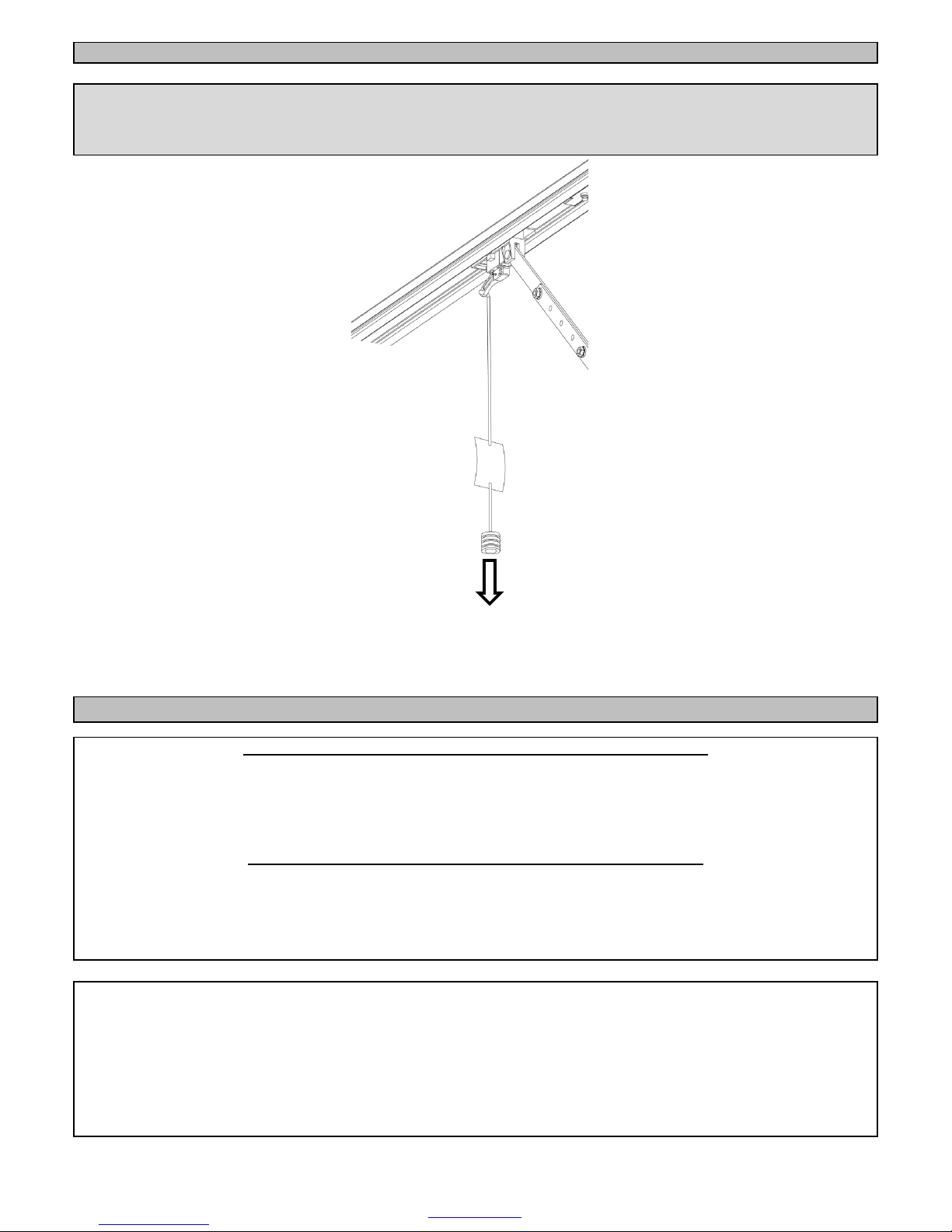
3. The emergency release cord in a garage door automation system must be installed where it is no higher than 1.8m from the floor level.
4. Any additional fixeddoorcontrol switches such as wall consoles orkeypads, if installed, mustbe at a height of at least 1,5m, within clear sight of the gate or
door and away from any moving components of the system.
5. Do not substitute anycomponent of product withanyother manufacturer’s part. ET Systems accepts no responsibility for thes afety and correct operation of
the automation system in this circumstance.

ET DC BLUE ADVANCED USER 2013.012.24.11.2016
4
www.et.co.za
6. It is highly recommended that a set of safety infra-redbeams be used in conjunctionwith this product.The safety beams must be installed in such a way that
the product is prevented from running when anything is in the path of the door or gate.
7. Over and above the recommendation to use safety infra-red beams with this product it is mandatory to install and use a safety beam set when using the
automatic closing feature. It is recommended that a warning light be fitted to any automation system.
After Installation: It IsThe Responsibility Of The Installer To Ensure The User:
1. Is proficient in the use of the manual emergency release mechanism.
2. Is issued with the documentation accompanying this product.
3. Understands that the gate or door may not be operated out of clear sight.
4. Ensures that children arekept clear of the gate or door area at all times,and thatchildren do not play with the remote transmitters or any fixed trigger switches
linked to the system.
5. Is instructed not toattempt to repair or adjust the automation system and tobe aware of the danger of continuing to use the automation system in an unsafe
condition before a service provider attends to it.
6. Is proficient in testing the unit’s safety obstruction sensing system.
7. Is aware ofwhat to check for with regards to wear and tear that may need to be attended to from time to time by the service provider.
8. Is aware thata fatigued batterymaynot be disposed of in the general refuse and mustbe handed in ata battery merchantfor safe disposal. Before removing
the battery fromthe systemthe household mains must bedisconnected. In the case of the motor unit being removed and scrapped, the battery must be
removed first.
0011014.005
* Based on the assumption that the door is balanced correctly and moving freely.
TECHNICAL SPECIFICATIONS
Model
DC BLUE ADVANCED Pico
DC BLUE ADVANCED
Primary power supply 220 – 240Vac @ 50hz 220 – 240Vac @ 50hz
Peak power consumption
100W peak @ (220 -240vac)
120W peak @ (220 -240vac)
Motor voltage
24Vdc
24Vdc
Maxi mum operations per day*
50 full cycles per 24hrs @ a rate of Max. 5
per hour
50 full cycles per 24hrs @ a rate of Max. 5 per
hour
Tra vel l er s peed*
8m/mi n
8m/mi n
Operating temperature range -10 to 50° C (14F to 122F) -10 to 50° C (14F to 122F)
Anti -crushing safety sensing
Yes - Electronicdigital profiling
Auxiliary supply output
24Vdc @ 250mA peak or 150mA continuous
Rated battery charging vol tage
27.5Vdc
27.5Vdc
Builtin receiver format
ET BLU MIX © enhanced rolling code.
Recei ver frequency 433.92Mhz 433.92Mhz
Memory
EEPROM
EEPROM
Applicable door types One pi ece trac kl es s ti p-up or multiplepanel
s ecti ona l over hea d singlewidth doors
One piece trackl ess tip-up or multiplepanel
s ecti ona l over hea d double width doors
Drawbar options(Ex-stock)
2.2m or 3.2m
2.2m or 3.2m or 3.7m
Applicable door sizes*
<10m²
<15m²

ET DC BLUE ADVANCED USER 2013.012.24.11.2016
5
www.et.co.za
CONTROL PANEL DASHBOARD
TOP
BOTTOM

ET DC BLUE ADVANCED USER 2013.012.24.11.2016
6
www.et.co.za
COMPONENT IDENTIFICATION AND DESCRIPTIONS

ET DC BLUE ADVANCED USER 2013.012.24.11.2016
7
www.et.co.za
USING THE EMERGENCY MANUAL RELEASE
WARNING!
Take care when operating the manual release. In the case of a damaged, broken or fatigued balancing spring, the door can
plummet downward when released from the drive via the emergency release cord!
SAFETY OBSTRUCTION SENSING IN ACTION
In the case of the door being resisted physically or obstructed while opening.
•The motor will stop running,
•The buzzer will beep once and operator reverts to standby mode.
•On the next BT button trigger the motor wi ll start cl osing the door.
In the case of the door being resisted physically or obstructed while closing.
•The motor will stop running,
•The buzzer will beep once as the motor immediately begins opening the door once again.
•On reaching the open position the operator reverts to standby mode.
•On the next BT button trigger the motor will begin the door closing.
NB! The safety sensing overload system needs to be tested at least once a month: -
(As prescribed by the SANS 60335-2-95 s afety code)
This is done by allowing thedoor to closeon to a 40mm x 40mm x 70mm block. The door should stop and reverse away when
encountering the block. If there areany signs of excessivestress to the mountings or mounting points on the door when doing this
test, your service provider must be contacted to repair or reinforce these points.
If uncertain about this test please make an appointment with your garagedoor service provider for a proper demonstration.
TO DISENGAGE AND MOVE
DOOR MANUALLY:
Warning!Doormay plummet
closed when released.
While pulling the emergency
release cord downward,
move the door open or
closed by hand.
TO RE-ENGAGE AND LOCK
DOOR BACK ONTO DRIVE:
Let the cord go and
move door open or
closed until the
sledge/traveller locks
back onto the chain
drive.

ET DC BLUE ADVANCED USER 2013.012.24.11.2016
8
www.et.co.za
BASIC OPERATING FEATURES
Basic open and close triggers using the (BT) button trigger.
Example 1. Simply opening the door fully and closing the door again fully.
Action
Response
Door in the closed position.
Courtesy l i ght off.
Press and release ei ther the
remote button trigger or the
hardwired trigger.
Door begins opening and
courtesy light switches on.
Wait for door to reach the full
open position.
Door stops and wai ts in the
open position. Courtesy light
remains on for a further 3
minutes.
Press and release ei ther the
remote button trigger or the
hardwired trigger.
Door begins closing and if the
courtesy light had previously
timed out and switched off, it
w
ill switch on again for three
minutes.
Wait for door to reach the
closed position.
Door stops in the closed
posi tion. Light remains on until
three mi nute ti mer ha s
expi red.

ET DC BLUE ADVANCED USER 2013.012.24.11.2016
9
www.et.co.za
BASIC OPERATING FEATURES
Basic open and close triggers using the (BT) button trigger.
Example 2. Using the (BT) button trigger input while the door is running.
Action
Response
Door in the closed position.
Courtesy l i ght off.
Press and release ei ther the
remote button trigger or the
hardwired trigger.
Door begins opening and
courtesy light switches on.
Press and release ei ther the
remote button trigger or the
ha rdwi red tri gger, before the
door reaches the full open
position
Door stops and waits for next
instruction. Courtesy light
remains on for a further 3
minutes.
Press and release ei ther the
remote button trigger or the
hardwired trigger.
Door begins closing and if the
courtesy light had previously
timed out and switched off, it
will switch on again for three
minutes.
Press and releaseei ther the
remote button trigger or the
hardwired trigger, while the
door is still closing.
Door stops and begins opening
once again. Light remains on
until three minute timer has
expi red.

ET DC BLUE ADVANCED USER 2013.012.24.11.2016
10
www.et.co.za
ADVANCED OPERATING FEATURES
Advanced triggers using the remote (BT) button trigger
(PARTY MODE)
Example 3. Using the remote (BT) button trigger to disable any closing triggers
Action
Response
TO ACTIVATE
Door in the closed position.
Courtesy l i ght off.
Press and release ei ther the
remote button trigger or the
hardwired trigger.
Door begins opening and
courtesy light switches on.
Stop door while opening or
simply wait until it reaches the
open position.
Door stops and waits at the
required open position.
Courtesy lightremains on for a
further 3 minutes.
Press and hold the remote
button trigger, +/- 10 seconds,
until buzzer beeps.
Buzzer beeps rapidly to
indicate party mode is active.
TO CONFIRM
Any attempt to operate the
door normally.
Buzzer repeats rapid beeps to
ind
icate the party mode is still
a cti ve.
The door will not move.
TO DE-ACTIVATE
Press and hold the remote
button trigger +/- 10 seconds,
until buzzer beeps.
Buzzer beeps once and door
starts closing.
Courtesy light switches on for
three mi nutes .
Rapid
Rapid

ET DC BLUE ADVANCED USER 2013.012.24.11.2016
11
www.et.co.za
ADVANCED OPERATING FEATURES
Advanced triggers via the remote (BT) button trigger and (LT) courtesy light trigger
(HOLIDAY LOCK-OUT MODE)
Example 4. Using the remote (BT) button trigger and (LT) courtesy light to lock out any opening triggers
Action
Response
TO ACTIVATE
Door must be closed Door in the closed position.
Courtesy l i ght off.
Press and hold remote
courtesy light button.
Courtesy light switches on.
Release button when buzzer
begins to sound. After +/- 5
seconds.
Buzzer tones for 5 seconds.
Courtesy light remains on.
Whilstbuzzer is still sounding,
Press and release the remote
trigger button, to activate
Holiday lock-out.
Buzzer beeps, light flashes
rapidly and display shows “H”
to indicate Holiday lock-out is
acti ve.
TO CONFIRM
Any attempt to operate the
door normally.
Buzzer beeps, light flashes
rapidly and display shows “H”
to indicate Holiday lock-out is
a cti ve.
TO DE-ACTIVATE
Press and hold remote
courtesy light button.
Courtesy l i ght swi tches on.
Release button when buzzer
begins to sound. After +/- 5
seconds.
Buzzer tones for 5 seconds.
Courtesy light remains on.
Whilstbuzzer is still sounding,
Press and release the remote
trigger button, to de-activate
Holiday lock-out.
Buzzer beep once, courtesy
light remains on and the door
begins opening as Holiday
lock-out de-acti vates.
Rapid
Rapid

ET DC BLUE ADVANCED USER 2013.012.24.11.2016
12
www.et.co.za
ADVANCED OPERATING FEATURES
Auto-close feature.
Action Response
Door in the closed position.
Courtesy l i ght off.
Press and release ei ther the
remote button trigger or the
hardwired trigger.
Door begins opening and
courtesy light switches on.
On reaching the full open
position, the auto-cl os e ti mer
times out the previously
programmed auto-cl os e ti me.
20 s ec. for exa mpl e.
Courtesy l i ght and buzzer,
flashes and sounds three
ti mes , before door begi ns
closing automatically.
ADVANCED FEATURES
Safety beam input
NB!! This input only affects the closing cycle.
Action
Response
Door closing.
Light on.
Interrupt the safety beams.
Display shows “b”, door stops
and begins opening once
again. Light remains on.
Safety beam still interrupted.
Door reaches full open
position. Display continues to
show “b” as long as the safety
beams are interrupted. Light
switches off after 3mi n.
Any further closing triggers
while beams are still
interrupted.
Door will not close. Display
continues to show “b” as long
as the safety beams a re
interrupted and buzzer beeps
once.
X 3

ET DC BLUE ADVANCED USER 2013.012.24.11.2016
13
www.et.co.za
ADVANCED FEATURES
Courtesy light
NB!! In the case of a household mains failure, the courtesy light does not function.
The buzzer will also emit a short beep every 15 seconds for 5 minutes after any BT transaction when the household mains power is
off.
Action Response
Every operation of the door
from any position.
Light will come on for 3
minutes and door operates.
If the light is off and the (L)
courtesy light button on the
remote i s pres s ed and
rel ea s ed.
Light will come on for 60
minutes.
If the light is on and the (L)
courtesy li ght button on the
remote i s pres s ed and
rel ea sed.
The courtesy light simply
switches off.
For 3 minutes
For 60 minutes

ET DC BLUE ADVANCED USER 2013.012.24.11.2016
14
www.et.co.za
A QUICK METHOD OF LEARNING A TRANSMITTER BUTTON CODE INTO THE RECEIVER MEMORY WITHOUT ENTERING THE
PROGRAMMING MENU.
Max users (BT) button trigger channel = 35 user codes
NB!! No remote codes can be learnt into the (LT) courtesy light channel this way.
Action Response
Door must be closed Door closed
Press and hold the “Up”
button until buzzer beeps and
display shows “b”.
Buzzer beeps once and display
shows “b”
Press and hold required
remote button.
LED on remote transmitter
remains lit.
Pres s a nd rel ea s e the “SET”
button.
“1” on display and 1 beep =
user code successfully
regi s tered.
“2” on display and 2 beeps =
us er code al rea dy in the
recei ver memor y.
“3” on display and 3 beeps =
Unsuccessful because no code
wa s s een wi thi n 4 s ec of the
“SET” button being pressed.
Mandatory timeout.
“F” on display and multiple
rapid beeps = Memory full
Rel ea se both the r emote
button and “SET” button
Display reverts back standby
mode “II”
Memory ful l
Code already in
memory
Successful
Unsuccessful

ET DC BLUE ADVANCED USER 2013.012.24.11.2016
15
www.et.co.za
WARNINGS WHEN USING A (BT) BUTTON TRIGGER FROM STANDBY MODE.
Display Buzzer and light Reason Resolve by.
Safety beam obstructed. Page 12
Holiday lock-out active. Pa ge 11
Party mode a cti ve. Page 10
Household mains power
failure.
Operating on battery
power only.
Re-connect household mains
supply.
To test. Check that li ght
switches on when operating
door.
Page 13
Door stops •Motor fuse blown or,
•Encoder faul ty or
disconnected.
•Repl a ce motor fuse or,
•Call your serviceprovider
to r econnect or repl a ce
encoder
Press and release “EXIT”
when done.
Rapid
Rapid
Light
1 short beep
every 15 sec.
(Beep stops 5
minutes after
each door
operation)

ET DC BLUE ADVANCED USER 2013.012.24.11.2016
16
www.et.co.za
WARRANTY:
1. All goods manufactured by ET NICE (Pty) Ltd carry a 12 month factory warranty from date of invoice.
2. All goods are warranted to be free of faulty components and manufacturing defects.
3. Faultygoods willbe repaired orreplaced at the sole discretion of ET NICE (Pty) Ltd free of charge within the warranty period.
4. This warranty is subject to the goods being returned to the premises of ET NICE (Pty) Ltd.
5. The carriage of goods is for the customer’s account.
6.
This warrantyisonlyvalidif the correct installation and application of goods, as laid out in the applicable documentation
accompanying said goods, is adhered to.
7. All warranty claims must be accompanied by the original invoice.
8. All claims made by the end user must be directed to their respective service provider/installer.
The following conditions will disqualify this product from the warranty as laid out above. These conditions are non-negotiable.
1. Any unauthorized non-manufacturer modifications to the product or components thereof.
2. Anymodification to the installation methods described in the installation instructi ons .
3. Anyapplication oruseof theproductotherthan the intended use and application described in the product documentation.
4. Any application and or usage of this product outside of the technical specifications limits prescribed for it.
5. Any use of the product where the due diligence prescribed in the “Be Safe” document is not adhered to.
In particular for this product:
•The us e of this product in heavy traffic a pplications such as office parks entrance/exits a nd re sidential complexes e ntrance/exits.
•The use of this product i n n on-weatherproof applications such as carports.
The following items are not included in the warranty or they carry a special warranty condition of their own.
1. The battery (Limited 6 month warranty)
2. The motor brushes.
3. Damage resultant of wind and other climatic influences such as lightning strikes.
4. Damage due to high voltage surges on the household mains.
5. Da ma ge due to i nfesta tion i.e. Ants nes ting…
6. Wa ter damage. It is the responsibility of the i nstaller to ensure the product isinstalled in a location that is protected from water
ingress. The ingress protection rating is specifiedin the accompanying documentation. Housings that require that cable entries are
made bythe installer donotcarryan ex-factory i ngress protection ratingasitistheresponsibilityofthe installer to seal the cable
entry points after installation of the cabling.
This manual suits for next models
1
Table of contents
Popular Garage Door Opener manuals by other brands

Power Master
Power Master H Installation and owner's manual

Entrematic
Entrematic EM PSL150 Installation and service manual

GiBiDi
GiBiDi AUTOBOX 3000 Instructions for installation

Alarmcom
Alarmcom MyQ installation guide

Keyautomation
Keyautomation Viper Instructions and warnings for installation and use

NASAB
NASAB E8 installation guide

Cardin
Cardin BLADE3 Installation and operating instructions

Genie
Genie DirectLift 2060 Operation and maintenance manual

SWS
SWS SeceuroGlide ELITE OPERATING & MAINTENANCE GUIDE

Genie
Genie Garage Door Opener Programming manual

Craftsman
Craftsman 139.53976SRT owner's manual

Cardin Elettronica
Cardin Elettronica 305/GLi824 instruction manual