1
Fig. 2
EF01.1
EF02.1
EE01
o/or/ou/
oder/ή
EE02
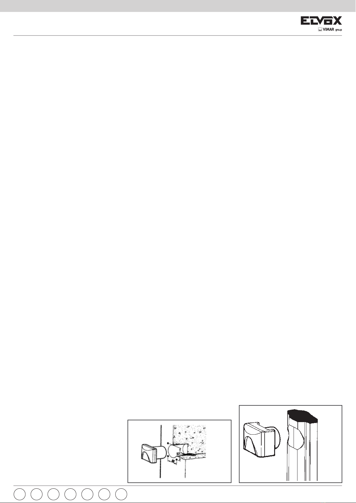
INSTALLAZIONE
- Separare il contenitore a incasso dal corpo della fotocel-
lula tramite le viti di fissaggio, dopo aver tolto il coper-
chio. Per togliere il copri fotocellula inserire un cacciavite
a taglio largo nella fessura ricavata nel lato inferiore del
coperchio e ruotarlo.
- Incassare il contenitore della fotocellula e applicare i tas-
selli al muro come indicato nella Fig. 2.
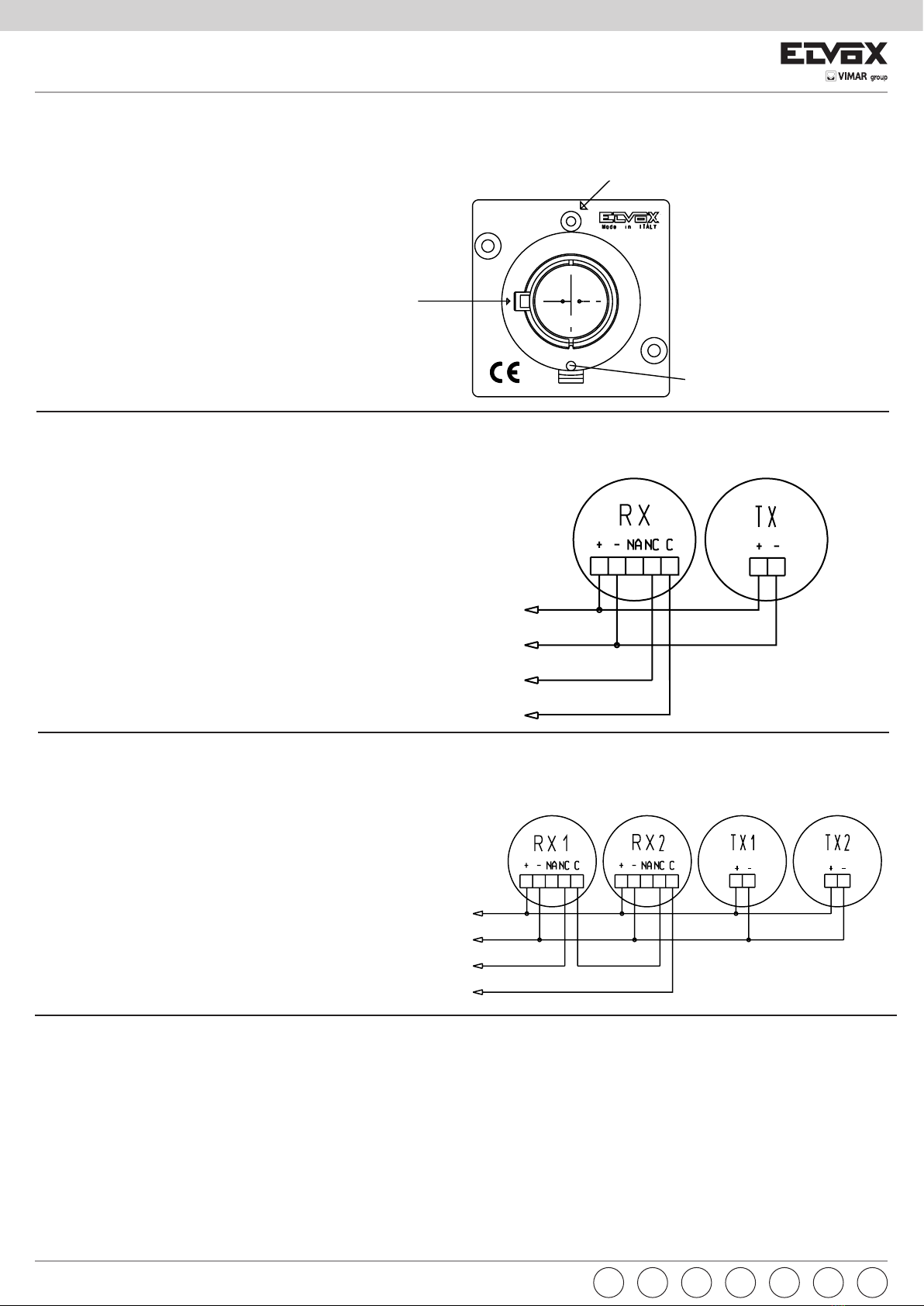
- Effettuare i collegamenti al corpo della fotocellula
tenendo i fili più corti possibile.
- Alimentare la centralina elettronica e controllare che la
tensione di alimentazione delle fotocellule sia di 12V c.c.
- Inserire e fissare con le viti in dotazione i corpi fotocellula
TX e RX ai contenitori esterni. Fig.4
1) Svitare leggermente la vite di fissaggio (vedi figura).
2) Orientare la fotocellula manualmente (vedi figura).
3) Riavvitare la vite di fissaggio.
- Eseguita la taratura della fotocellula controllare il funzio-
namento interrompendo più volte il fascio, il led rosso
sulla ricevente si accende ed avviene la commutazione
dei relè. Eseguito il collaudo posizionare il frontalino tra-
sparente RX e TX.
- Controllare il funzionamento interrompendo più volte il
raggio infrarosso.
Per l’installazione della versione per colonnina utilizzare le
fotocellule articolo EF02.1 (Fig. 3).
Per l’alloggiamento della fotocellula nei muri in calcestruzzo,
utilizzare la scatola Art. ZX26.
INSTALLATION
- Remove the cover and extract the flushmounted case
from the photocell body by undoing the securing screws.
To remove the photocell cover insert a large flathead
screwdriver in the slot in the lower part of the cover and
turn.
- Flush-mount the photocell housing and fit the expanding
plugs with screws to the wall according to Fig. 2
- Make the electrical connections to photocell bodies, keep-
ing the wires as short as possible.
- Supply power to the electronic switchboard and check that
the photocell supply voltage is 12V DC.
- Insert the TX and RX photocell bodies, fixing in position
using the screws supplied with the outside box. Fig. 4
1) Slacken off the securing screw (see figure).
2) Align the photocell by hand or by inserting a screwdriver
at A (see figure).
3) Tighten the securing screw.
- Set the photocell by inserting check the operation by in-
terrupting the beam several times, the red LED on the
passive photocell is lit and the relays effect the switching.
After testing, position the RX and TX transparent front
pieces.
- Check operation by interrupting the infrared ray several
times.
When installing the column-fitted model, use the EF02.1 pho-
tocell (fig. 3).
When housing the photocells in cement walls, use the spe-
cially prepared ZX26 box.
INSTALLATION
- Séparer le boîtier à encastrer de la photocellule au moyen
des vis de fixation, après avoir retiré le couvercle. Pour
retirer le couvercle, introduire un tournevis large dans la
fente ménagée dans le côté inférieur du couvercle et le
faire tourner.
- Murer le boîtier de la cellule photoélectrique et appliquer
les vis à goujons à la paroi comme indiqué dans la Fig. 2.
-
Connecter la cellule photoélectrique de façon à ce que les fils
soient les plus courts possibles.
- Alimenter la centrale électronique et controler que la ten-
sion d’alimentation des photocellules est 12V c.c.
- Introduire I’émetteur TX et le récepteur RX dans les
boîtiers d’extérieur et les fixer avec les vis fournies. Fig. 4
1)
Dévisser légérement la vis de fixation (voir figure)
2) Orienter la cellule photo-électrique à la main ou en intro-
duisant la pointe d’un tournevis au point A (voir figure).
3) Revisser la vis de fixation.
- Après la mise au point de la cellule photoélectrique, con-
trõler le fonctionnement en interrompant plusieurs fois le
rayon. Le LED rouje sur la photocellule passive s’allume
et les relais effectuent la commutation. Après la mise au
point, appliquer le couvercle transparent sur l’émetteur et
le récepteur.
- Contrôler le fonctionnement en interrompant piusieurs fois
le rayon infrarouge.
Si la cellule photoélectrique doit etre montée sur un pilier,
utiliser le modèle EF02.1 (fig. 3). Si la cellule photoélectrique
doit être Encastrée dans un mur en béton, utiliser le boîtier
Art. ZX26.
INSTALAÇÃO
- Separar o contentor a embeber do corpo da fotocélula
através dos parafusos de fixação, após ter retirado a
tampa. Para retirar a tampa da fotocélula inserir uma
chave de parafuso na fissura existente na parte inferior
da tampa, e rodá-la.
- Embeber o contentor da fotocélula e aplicar as calhas à
parede conforme à Fig. 2.
Procurar obter o melhor alinhamento.
- Efectuar as ligações de modo a que os condutores
fiquem o mais curtos possível.
- Alimentar a central electrónica e verificar se a tensão de
alimentação das fotocélulas é de 12 V c.c.
- Inserir os corpos das fotocélulas TX e RX e fixá-las, com
os parafusos fornecidos, nos contentores externos. Fig. 4
1) Desaparafusar levemente o parafuso de fixação (ver fig-
ura).
2) Orientar a fotocélula com as manos ou inserindo a punta
duma chave de parafuso no pormenor A (ver figura).
3) Parafusar o parafuso de fixação.
- Efectuada a calibragem da fotocélula verificar o funcio-
namento interrompendo varias vezes o feixe. O LED ver-
melho sobre a fotocélula passiva se ilumina e os relés
efectuan a comutação. Efectuado o teste, colocar a parte
de frente transparente RX e TX.
- Controlar o funcionamento interrompendo várias vezes os
raios infravermelhos.
Nas versões de coluna utilizar as fotocélulas EF02.1
(Fig. 3).
Para o alojamento da fotocélula nas paredes de betão,
utilizar a caixa Art. ZX26.
INSTALACIÓN
- Separar el contenedor de empotre del cuerpo de la fo-
tocélula por medio de los tornillos de fijación, después
de haber quitado la tapa. Para quitar el cubrefotocélula
insertar un destornillador a tajo ancho en la hendidura
obtenida en el lado inferior de la tapa y rodarlo.
- Empotrar el contenedor de la fotocélula y aplicar los
tacos a la pared como indica la Fig. 2.
- Efectuar los conexionados al cuerpo de la fotocélula
manteniendo los hilos los más cortos posible.
- Alimentar la central electrónica y controlar que la tensión
de alimentación de la fotocélulas sea de 12V c.c.
- Insertar y fijar con los tornillos en dotación los cuerpos
fotocélulas TX y RX a los contenedores externos. Fig. 4
1) Destornillar ligeramente el tornillo de fijación (ver figura).
2) Orientar la fotocélula con las manos o insertando la punta
de un destornillador en el particular A (ver figura).
3) Antornillar el tornillo de fijación.
- Efectuada la calibración de la fotocélula controlar el fun-
cionamiento interrumpiendo varias veces el haz, el LED
rojo sobre la célula pasiva se ilumina y los relés efectúan
la conmutación. Efectuado el control final posicionar la
parte frontal transparente RX y TX.
- Controlar el funcionamiento interrumpiendo varias veces
el rayo infarrojo.
Para la instalación de la versión para columna utilizar las
fotocélulas artículo EF02.1 (Fig. 3).
Para el alojamiento de la fotocélula en las paredes en
hormigón utilizar la caja Art. ZX26 predispuesta para eso.
INSTALLATION
-
Unterputzdose nach Abnehmen des Deckels mittels der
Befestigungsschrauben vom Fotozellenkörper Trennen.
Zur Entfernung der Fotozellenabdeckung einen Breit-
schlitz-Schraubenzieher in den Schlitz an der unteren Seite
des Deckels stecken und drehen.
- Das Photozellgehäuse einmauern und die Dubeln mit
Schrauben auf die Wand wie in Abb. 2 einbauen.
- Die Anschlüsse durchführen und dabei die Kabel so kurz
wie möglich halten.
- Die Steuerelektronik mit Strom versorgen und kontrol-
lieren, ob die Versorgungsspannung der Fotozellen 12V
Gleichstrom beträgt.
- die Photozellengehäuse für Senden und Empfang einset-
zen und mit den zugehörigen Schrauben befestigen, die
den Außengehäusen mitgeliefert werden. Fig. 4
1) Die Befestigungsschraube etwas lockern (s. Abb.).
2) Die Lichtschranke mit den Händen oder durch Einführen
der Spitze eines Schraubenziehers in Bauteil A ausricht-
en (s. Abb.).
3) Die Befestigungsschraube erneut arretieren.
- Nach erfolgter Einstellung der Photozellen die Funktion
durch mehrmaliges Unterbrechen des Lichtstrahls prüfen.
Die rote LED auf der Empfängerphotozelle beleuchtet
und die Relais durchführen die Umschaltung. Nach er-
folgter Überprüfung ist die transparente Frontblende von
Sender und Empfänger einzusetzen.
- Die Funktion durch mehrmaliges Unterbrechen des Infra-
rot-Strahls prüfen.
Zur Installation der Säulenausführung, die Photozellen Art.
EF02.1 (Abb. 3) verwenden. Zur Aufnahme der Photozelle in
Betonwänden, das entsprechende Einbaugehäuse Art. ZX26
verwenden.
ΕΓΚΑΤΑΣΤΑΣΗ
- Αφαιρέστε το χωνευτό κουτί από το σώμα του φωτοκυττάρου
μέσω των βιδών στερέωσης αφού βγάλετε το κάλυμμα. Για
να αφαιρέσετε το σώμα του φωτοκυττάρου, τοποθετήστε ένα
πλατύ κατσαβίδι στην εγκοπή που υπάρχει στην κάτω πλευρά
του καλύμματος και περιστρέψτε το.
- Εντοιχίστε το κουτί του φωτοκυττάρου και τοποθετήστε τα
ούπα στον τοίχο, όπως φαίνεται στην εικ. 2.
- Πραγματοποιήστε τις συνδέσεις στο σώμα του φωτοκυττάρου
με όσο το δυνατόν πιο κοντά καλώδια.
- Τροφοδοτήστε με ρεύμα την ηλεκτρονική κεντρική μονάδα και
ελέγξτε εάν η τάση τροφοδοσίας των φωτοκυττάρων είναι 12V
c.c.
- Τοποθετήστε και στερεώστε με τις παρεχόμενες βίδες τα
σώματα των φωτοκυττάρων TX και RX στα εξωτερικά κουτιά.
Εικ. 4
1) Ξεβιδώστε ελαφρώς τη βίδα στερέωσης (βλ. εικόνα).
2) Στρέψτε το φωτοκύτταρο με το χέρι (βλ. εικόνα).
3) Βιδώστε ξανά τη βίδα στερέωσης.
- Όταν εκτελεστεί η βαθμονόμηση του φωτοκυττάρου, ελέγξτε
τη λειτουργία διακόπτοντας πολλές φορές τη δέσμη. Η κόκκινη
λυχνία led στο δέκτη ανάβει και εκτελείται εναλλαγή των ρελέ.
Μετά τον έλεγχο, τοποθετήστε το διαφανές μπροστινό τμήμα
των RX και TX.
- Ελέγξτε τη λειτουργία διακόπτοντας πολλές φορές την
υπέρυθρη ακτίνα.
Για την εγκατάσταση της έκδοσης για κολόνα, χρησιμοποιήστε τα
φωτοκύτταρα κωδ. EF02.1 (εικ. 3).
Για την τοποθέτηση του φωτοκυττάρου σε τοίχους από σκυρόδεμα,
χρησιμοποιήστε το κουτί κωδ. ZX26.
PTESDEFRENI EL
Fig. 3