Automation Systems AUSTRALIA TiTAN 2410 User manual
Titan 2410
Advanced Digital Sliding Gate System
REV 0
Step by Step Simple Installation
Guide on Page 2
Automation Systems
Australia

Table of Contents
1
Specifications, Dimension and Tools Required
2
Step By Step Installation Guide
3
Installation Layout/Wiring Layout
4
Motor Installation
5
Motor Installation Continued
6
Controller Layout and Display Screen Status
7
CERO Standalone Solar System Connection
8
Battery Backup Connection, Power Transformer Connection
9
SPEED, TIME and SENS Trim pot Adjustments, System Menu Hierarchy
10
Basic Menu (operating logic)
11
Basic Menu continued ( wireless learning, automatic closing time, working time learning, fast speed
level and Motor Test)
12
Core Menu (manual time adjustments, gate direction, photocell, stop, limit switch polarity)
13
Core Menu continued (special detector, soft start, opening edge, closing edge, manned depot mode)
14
Core Menu continued (light output, auxiliary light output, receiver mode
15
Remote Learning (detailed)
16
Remote Deleting (detailed), Remote Usage
17
Enrolment, Wireless Keypad Learning (detailed), Automatic Closing Timer
18
Motor Test
19
Learn Time Calibration/Gate Calibration
20
Photocells Dukie and Dukie+
21
Special Detector Dukie and Dukie+
22
Traffic Light, Driveway Light, Alert Strobe and Warning Lights
23
Tekno Wi-Fi Switch, Loop Detector, Tekno K1 Keypad
24
Tekno GSM Intercom, Digital Weekly Timer, Push Button
25
Emergency stop button, amplify antenna
26
Fill In Enrolment List
27
Warranty Terms

Page 1
Operating Voltage
24V AC/24V DC
Standby Consumption
~40mA
Battery Backup
Yes
Speed
22-36 CM/S
Motor Limit
N/C Micro Switch
Torque
27 NM
Duty Cycle
90%
Light Output
Warning 12VDC 1A MAX / Secondary Relay Max 3A
Accesories Power
12V DC (250mA)
Safety Inputs
Photocell, Detector, Safety Edge
Operation Temprature
-10°C to +60°C
Remote Button Capacity
250
Specifications
Dimensions
Typical Tools Required
2/2.5mm Flat Head for
Terminal Connections
Socket & Spanner
Sets
Drill and Drill Bits
Masonry and Metal
Multi Meter
(not essential)
Wire Stripper
318
17
170
25mm Conduit
MAX.
80
80
1
2
.
9
4
m
m
Gate Length (mm)
Gate Weight (Kg)
3500
mm
600 Kg
1000 Kg 1000 Kg
300 Kg
400 Kg
800 Kg
4000
mm
5000
mm
6000
mm
7000
mm
8000
mm
*Tested ratings are level gate installations and does not take into account
inclined installations
Page 2
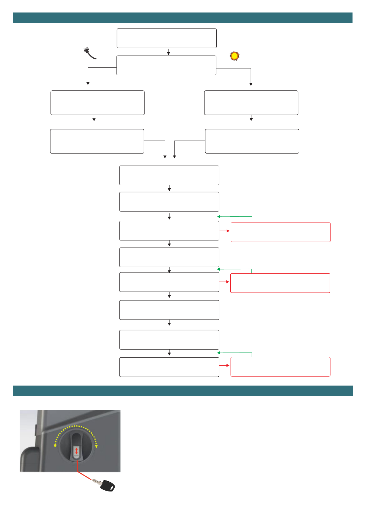
Connect in WIRED accesories
Install gate motor, rack and limit
strikers
Turn on the Power Point
Connect Battery Backup (if
applicable)
Connect Solar System
Turn ON the load output on the solar
regulator
Configure applicable safety devices,
Photocell type, special detector and STOP
Test Safety Devices
Run the motor Test
Automatic Learning Cycle
Test system using a remote
Set the automatic closing timer (if
required)
Adjust SPEED, TIME and SENS
TROUBLESHOOTING
Set the correct direction by following the
troubleshooting
Pair remotes and wireless keypads
Set the gate operating Direction
Step by Step Installation Guide
See accessories pages or there specific manuals
Remote’s are Pre-set
if purchased
with the system
Electric System Path Solar System Path
PAGE. 7
PAGE. 7
PAGE. 8
PAGE. 12
PAGE. 15
PAGE. 18
PAGE. 19
PAGE. 18
PAGE.9
PAGE. 17
PAGE. 20/PAGE. 21
PAGE. 20/PAGE. 21
To manually release (disengage clutch):
1. Slide the key cover UP
2. Insert the key (fits only one way into the cylinder) and turn the key clockwise.
3. Turn the lever one full turn clockwise (360°)
Gate can now be moved by hand.
To return to automated mode (engage clutch):
1. Turn the lever one full turn counter-clockwise (360°)
2. Insert the key (fits only one way into the cylinder) and turn the key counter-clockwise.
3. Slide the key cover DOWN
Gate cannot be moved by hand and is ready for automated use.
Manual Release

Page 3
L
C
F
D
G
M
H
N
O
I
A
Number
Accesory
Requirments
A
Gate Motor
Power by transformer or Solar
C
Entry Keypad
Dex 4 (wireless), All others wired to gate controller by 4 core cable
D
Exit Keypad
Dex 4 (wireless), All others wired to gate controller by 4 core cable
E
Gate Stop
Physically Mounted Hardware Item. Mandatory Stop to prevent accident or injury incase of
failure
F
Induction Loop
Housed inside gate controller with 1 core cable for the driveway loop
G
Photocell Transmitter
No cable required for Dukie+, Standard Dukie 2 core Cable to gate controller
H
Photocell Receiver
4 Core cable to gate controller
I
Gate Controller Power Source
Mains, Outdoor Transformer or Solar Panel to the Gate Controller
J
Meeting Point
Physically Mounted Hardware Item
K
Gate Top Guide
Physically Mounted Hardware Item
L
Ground Track
Physically Mounted Hardware Item
M
ADDITIONAL Photocell
Transmitter
Optional Additional Safety Device, No cable required for Dukie+, Standard Dukie 2 core
Cable to gate controller
N
ADDITIONAL Photocell
Receiver
Optional Additional Safety Device, 4 Core cable to gate controller
O
Automatic Light
2 core cable to gate controller
Optional Wireless Dukie+
Optional Wireless DEX 4
Optional Wireless DEX 4
Additional Safety Sensor M/N is optional
Optional Wireless Dukie+
FENCE FENCE
POST
GATE
POST
Installation Layout
E
K
J

Page 4
Step 1
Step 2
Step 3
Step 4
Identify the OPENING direction of your gate based on the illustrations below.
Gate opens to the LEFT or RIGHT is always made from the inside looking towards the street (outside).
Mark the centre of the mounting holes of the base plate, note the orientation of the large conduit entry hole.
The base plate should be positioned within 50mm from the support post/edge of the driveway.
The base plate is positioned 55mm away from the backside of the gate to achieve the correct base distance for the
limit switch spring and gear rack alignment. The motor distance can be fine tuned when installing to the base plate.
Drill the four fixing hole using a 10mm masonry drill, ensure that the holes are cleaned
thoroughly in preparation to install the dyna bolts.
Install the base plate ensuring it is stable, if unstable against the concrete (can tilt back and
forth) install with washers from the under side (with at least a 10mm ID) to achieve level.
The dyna bolt will slip through the base plate then the washer. Tighten the dyna bolts.
Install the gate motor to the metal base plate, ensure the front of the plate (side facing the
gate) is flush with the front of the gate motor.
RIGHT
HAND SIDE
OPENING
Final Travel
RIGHT HAND SIDE OPENING
LEFT
HAND SIDE
OPENING
Final Travel
LEFT HAND SIDE OPENING
Inside Property
Outside Outside
3.20 mm
50
mm
Edge of
support post/driveway
Conduit opening to the LEFT
50mm
5.92 mm
GATE
3.20 mm
50
mm
Edge of
support post/driveway
Conduit opening to the LEFT
50mm
5.92 mm
GATE
⌀10mm
Flush Faces
Motor Installation
titan 2410
Automation Systems
Australia

Page 5
Step 5
Step 6
Step 7
Step 8
Manually Release the gate motor and set the gate 250mm from the open position .
Sit a piece of gear rack on top of the motors pinion gear and level it according to the
gates current level (adjustable later), allow for a 2-3mm clearance (backlash) between
the top of the pinion tooth and the base of the gear rack.
Screw in the first piece of gear rack in place using self drilling metal screws in the
CENTRE of the elongated hole.
Slide in the next adjoining piece of gear rack and close the gate by hand til the pinion is
centred to the ne piece of gear rack that has been added, once again as per the
previous step the rack should be levelled according to the gates current level
(adjustable later), once again allow for a 2-3mm clearance (backlash) between the top of
the pinion tooth and the base of the gear rack.
Screw the piece of gear rack in place using self drilling metal screws in the CENTRE of
the elongated hole.
Repeat this step until the gate has gear rack installed across its entire length.
Install the TWO bolts to each striker plate.
OPEN the gate til 50mm before it touches the gate stop.
Install the striker plate to the gear rack THE SPRING SHOULD BE BENT to 45°, the
striker plate CLAMPS to the gear rack and does not require any holes to be drilled.
CLOSE the gate til 20mm before it touches the meeting points base.
Install the striker plate to the gear rack THE SPRING SHOULD BE BENT to 45°, the
striker plate CLAMPS to the gear rack and does not require any holes to be drilled.
Cut off any EXCESS gear rack using an angle grinder, ensure the motor cover is installed and the excess rack is in the furthest possible and safe
position away from the motor, cutting will produce sparks due to the racks steel core, ensure no stray sparks reach the gate motor to avoid damage.
Slip on the side covers on each side to cover the mounting bolts.
Move the gate to the half way point and engage the clutch and proceed to Motor Testing
Manually open and close the gate at a very slow speed, observe that the gear rack always retains the 2-3mm clearance backlash.
If the gate feels tight in certain areas most likely the backlash is less than advised, loosen the gear rack piece and adjust to correct then re-test.
If the gate feels loose in certain areas or the rack slips off the pinion most likely the backlash is greater than advised, loosen the gear rack piece and
adjust to correct then re-test.
Approx.
100mm
Base of gear
rack
to concrete
1 4 . 1 7 m m
Pinion
2-3 mm space between the
Top of Pinion Tooth
and the gear rack root
0 . 7 7 m m
Gate has travelled all the way to the right and has engaged the spring Gate has travelled all the way to the left and has engaged the spring
Page 6
Automation Systems
Australia
Premier SL24
SP
–-
99
Ec
dt
oP
Fo
PS
Pc
Eo
cL
Fc
.
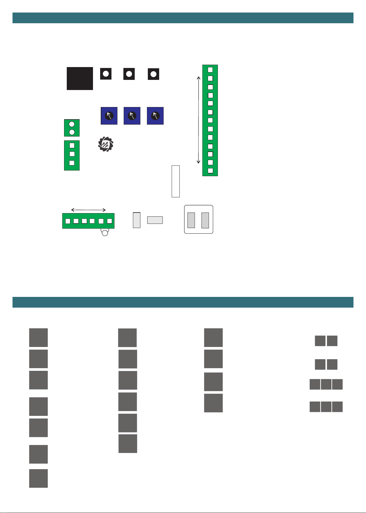
Display Screen Status
Controller Layout
Safety Status
General
Standby
Automatic Closing Timer
STOP Input Active
Photostop Input Active
(Special Detector)
Detector Input Active
(Special Detector)
Edge Input Active
(Opening Edge)
Edge Input Active
(Closing Edge)
Photocell Input Active
Opening
Fast Speed 0.5 Second Flash
Slow Speed 1 Second Flash
Full Open Position
Closing
Fast Speed 0.5 Second Flash
Slow Speed 1 Second Flash
Full Close Position
Battery Backup Mode
(Flashes)
UP
SPEED SENS TIME
MODE DOWN
8.8.
PD/CL
ST/OP
ANT
ANT
GND
COM
PS/DT
PT/EC
COM
LO
LC
SP/E0
COM
LPW
OUT 12V
LIGHT
Courtesy
Gate Open
RED GREEN C
M
PC
315
16 21
25
30 31
29
26 27 28
+
+
+
-
-
-
1
2
345678910 11 12 13 14 15
16 17 18 19
24
20
23
21
22
33
+
-
34
32
24V AC
DC - DC +
FUSE
32. 15A Fuse
33. Battery Terminal
34. 24V AC Input/ 24V DC Solar REGULATOR Input
16. +12V DC Accessories (ENERGY SAVER)
17. -12V DC Accessories (ENERGY SAVER)
18. Light Output + (Transformer voltage)
19. Lock Output -
20-21. Motor Terminal
15. Negative for Constant Accessories Output
14. Constant 12V Accessories Output (Regulated)
13. Limit Switch Common Blue
12. SP/E0 (Open Edge Device/STOP Input)
11. Limit Switch White
10. Limit Switch Black
9. COMMON to 8 & 12
8. PT/EC (Closing Edge Device)
7. Special Detector
6. Photocell Input (Configurable for N/O or N/C Circuit)
5. COMMON to 3,4,6 & 7
4. Pedestrian/Close Input (N/O Circuit)
3. Start/Open Input (N/O Circuit)- Set by operating logic
25. Digital Display
26. UP Button
27. MODE/OK Button
28. DOWN Button
2. ANT GND
1. Antenna
22. Red Light Relay (3A Max)
23. Green Light /Courtesy Relay (3A Max)
24. RELAY COMMON
29. Slow Speed Adjustment (SPEED)
30. Obstacle Detect Adjustment (SENS)
31. Slow Speed Travel Time (TIME)
St
oP
Pd
cL
Operating Input Status
Start Input Active
Open Input Active
Pedestrian Input Active
Close Input Active
Operating Logic
Operating Logic
Operating Logic
Operating Logic
St At
St At
oc oA cd
oc oA cd

Page 7
A standalone solar system is a totally off grid solution used for green energy initiatives or simply when its not possible to run power to the
gate system. To conserve power constant power draw devices such as wired keypads are not to be used, the alternative is a wireless
keypad as they use there own batteries.
+
-
Controller
CERO Standalone Solar System Connection
+
-
24V AC
BATT DC - DC +
Shelf Lower
Position
+
+
-
-
Link Wire
Link Wire
B1
B1
B2
B2
1. A solar panel CANNOT be installed under a tree, it
requires sun to charge and maintain the batteries.
2. A solar system is often maintenance free BUT the
batteries may require a external charge in the winter
months due to lack of sun (rare).
3. Constantly powered accessories such as wired keypads
will increase the standby current draw, solar panel or
battery upgrades may be required if sufficient collection is
not achieved.
Solar
Panel
Battery
System
Load
Output
+++
---
MENU SET
Multiple Panels in Parallel
Solar
Panel
+-
17aH Battery System
+
+
-
-
Battery
System
+-
Link Wire
Link Wire
Solar
Panel
Battery
System
Load
Output
+++
---
Page 8
+
-
24V AC
BATT DC - DC +
+
+
-
-
Transformer BLUE Low Voltage Common
Transformer BROWN LOWER OUTPUT
(LOW VOLTAGE)
Transformer GREEN HIGHER OUTPUT
(LOW VOLTAGE)
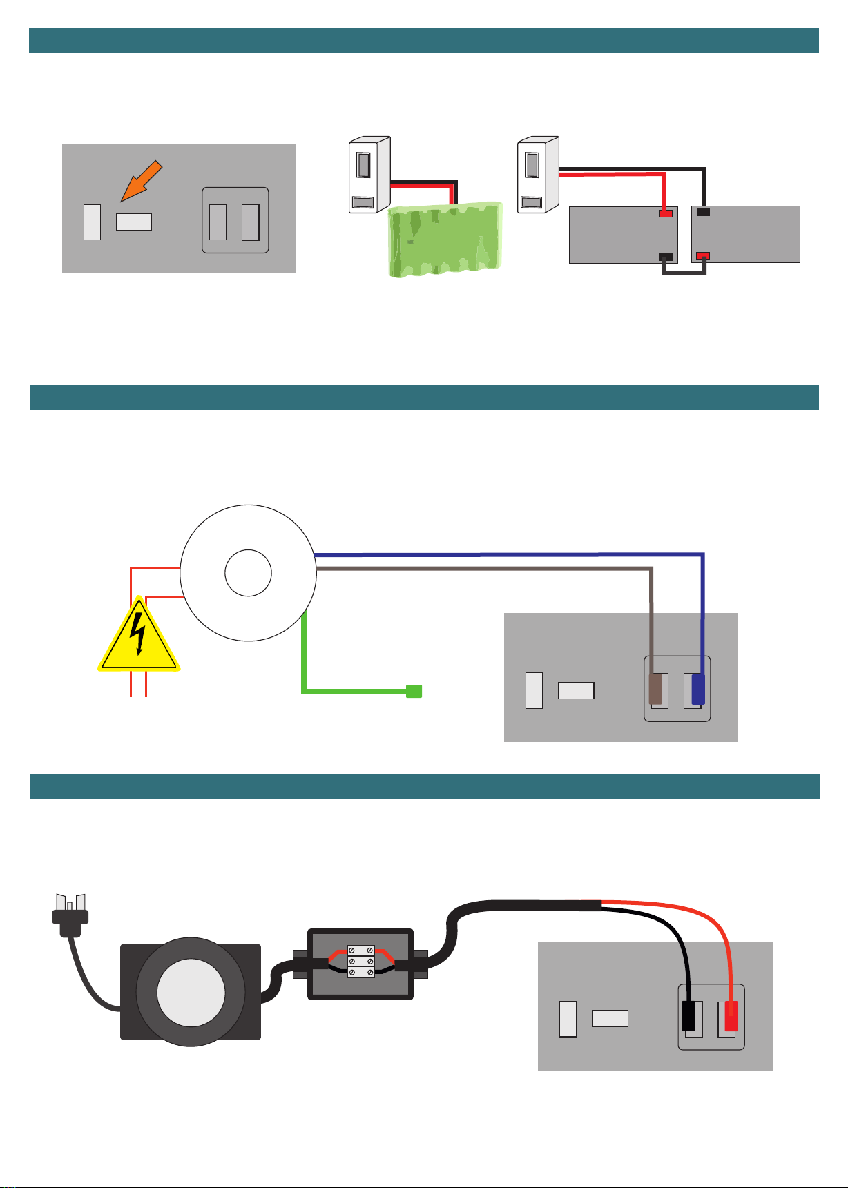
The battery backup will allow for uninterrupted usage in case of a power disruption. The battery backup system can operate the gate for
a period of 24 to 36 hours during the power disruption. Once the power is restored the system will automatically recharge the battery
system ready for the next use.
Note: When in battery backup mode the slowdown is disabled automatically to overcome any difference in speed.
The transformer on a mains powered system is the primary source of power, it takes the high voltage input and transforms to low voltage
which is connected to the controller. By default the controller uses the lower of the two outputs (brown wire) which is typically suggested
for most gate installs however incase required due to gate forces it would be suggested to swap the lower output (brown wire) for the
higher output (green wire).
HIGH VOLTAGE
LN
Battery Backup Connection
Battery Pack SLA Batteries
Multi Output Toroidal Transformer (Internal)
To connect the battery backup simply plug the
two pin connector in the correct orientation
into the battery port on the controller.
To connect the battery backup plug in the spade
connectors according to the above illustration then
plug the two pin connector in the correct
orientation into the battery port on the controller.
LINK
+
+
-
-
24V AC
24V AC
BATT
BATT
DC -
DC -
DC +
DC +
Where a power point is not available at the gate the Outdoor Transformer is used as the primary source of power, it takes the high
voltage input and transforms to low voltage which is connected to the controller through the low voltage extension cable for a maximum
distance of 120 metres.
Outdoor Low Voltage Weatherproof Transformer
Junction Box
Outdoor
Transformer
LOW VOLTAGE
Extension
Cable
Page 9
SPEED
SPEED
SENS
TIME
SENS
TIME
The “SPEED” Trim pot is the slow speed trimmer allowing a fine tuning of the SLOW Speed
portion of the operating cycle, Typically adjustment range is 20% to 50% from the
slowest speed (minimum) depending on gate size, weight and inertia.
Slowest Speed
Most Sensitive
(Least Push)
Later Slow
Down Point
Fastest Speed
Least Sensitive
(Most Push)
Earlier Slow
Down Point
The “SENS” Trim pot is the pressure sensing adjustment before the controller
recognises cut-off. Gate and Environmental factors will determine how high or low to
adjust based on gate weight and the required power to operate the motor.
Setting too high will affect how quickly the controller will shut off under load or
accident. setting too low can cause the controller to shut off too early (too sensitive)
and cause intermittent operations.
The “TIME” Trim pot is the adjustment in where the controller introduces the slow
down speed. A TOO late position may cause the gate to stop more abruptly as it
has not had enough time to decrease the speed of movement.
A TOO early position may cause difficulties in overcoming resistance points within
the sliding moment of the gate and also creates a slower operating cycle time which
may be undesirable.
“SPEED” Slow Speed/De-acceleration Adjustment
“SENS” Obstuction/Overcurrent Adjustment
“TIME” Slow Down Position Adjustment
–-
c 1
EH
tN
oL
UP
UP
MODE
MODE
DOWN
DOWN
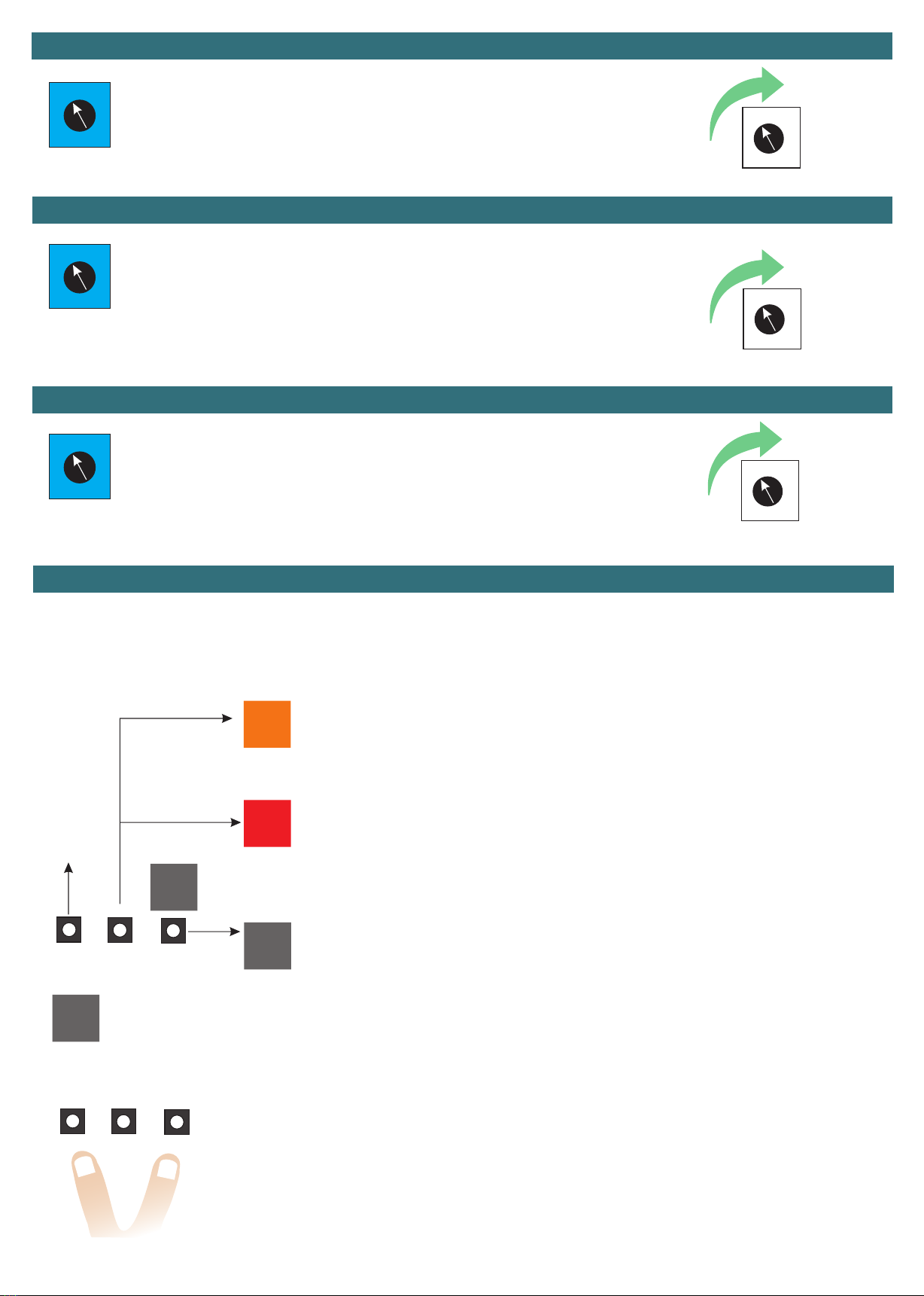
FROM STANDBY Press MODE Once to reach the Base Menu
Contains Logic Setting, Automatic Closing Time Setting , Learning Times and Remote Learning
(See Pages 10 and 11)
FROM STANDBY HOLD MODE for FOUR SECONDS to reach the CORE Menu Contains Primary
Adjustments for operation and configuration
(See Pages 12,13 and 14 )
FROM STANDBY Press Down, this is a shortcut to Remote Learning
Complete Remote Learning and Deleting can be reached through the Base Menu
EXIT will take you back one level
From preliminary menus it will return to standby
From any setting menu it will cancel the change and return you to the preliminary menu
If in a setting adjustment and you wish to cancel press UP and DOWN together momentarily to return back
one level.
If in a preliminary menu it will function the same as scrolling to exit.
Press MODE
Press
Down
HOLD
UP
Hold MODE
Preliminary Menu (BASIC)
Preliminary Menu (CORE)
STANDBY
Remote
Learning
Shortcut
Automatic
Learning
Shortcut
System Menu Hierarchy
Throughout the manual to simplify identification the two preliminary menus will be displayed with a coloured background as illustrated
below, any sub-menus and exit will be displayed with a grey background.

Page 10
oL
St
At
oc
oA
cd
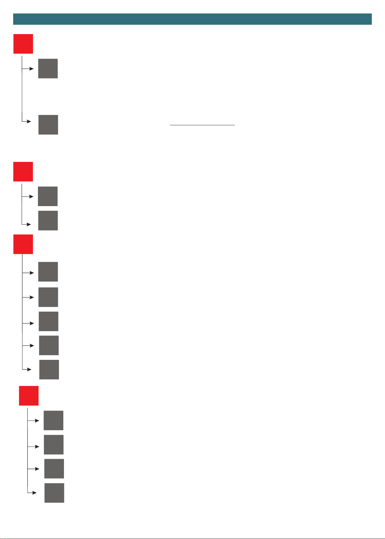
Setting the system Operating Logic (Default Standard)
Standard
Operates OPEN/CLOSE by remote and/or wired-wireless accessories
Standard WITH Automatic Closing Timer Adjust the Automatic Closing Timer in SP menu
Operates OPEN remote and/or Wireless Accessories with an automatic closing timer (can still
be closed earlier by remote and/or wired-wireless accessories)
Timer can be cancelled using the STOP feature
Typical Complex
Operates OPEN/CLOSE by remote and/or wired-wireless accessories with the WIRED input
terminals switching to loop detector mode OPEN Terminal and CLOSE Terminal
Typical Complex WITH Automatic Closing Timer Adjust the Automatic Closing Timer in SP menu
Operates OPEN/CLOSE by remote and/or wired-wireless accessories with the WIRED input
terminals switching to loop detector mode OPEN Terminal and CLOSE Terminal along with an
automatic closing timer (can still be closed earlier by remote and/or wired-wireless accessories)
Timer can be cancelled using the STOP feature
Secure Complex Mode WITH Automatic Closing Adjust the Automatic Closing Timer in SP menu
Ignores additional commands during opening, automatic closing by the adjustable timer ONLY,
no other methods to close
Basic Menu
OPEN
OPEN
/STOP/
CLOSE
OPEN
OPEN
N/A
Ped. OPEN
/STOP/
CLOSE
CLOSE
CLOSE
Driveway
Light
Driveway
Light
Driveway
Light
Driveway
Light
Cancel Automatic Closing Timer
Stop/Cancel Automatic Closing Timer
Stop
Stop/Cancel Automatic Closing Timer
Lc
c 1 c3
c2 c4
Remote Channels
oc
oA
cd
Operating Logic
St At
oL
OPEN
OPEN
OPEN
OPEN
/STOP/
CLOSE
Ped. OPEN
/STOP/
CLOSE
CLOSE
CLOSE
N/A
Terminal 4
(PD/CL)
Wired Input Terminals
Terminal 3
(ST/OP)
“OPEN” only commands always restart an automatic closing timer (if applicable).
any “STOP” command by remote control always cancels the automatic closing timer (if applicable).
any “CLOSE” command will bypass the automatic closing timer (if applicable) and close the gate.

Page 11
Lt Learn Working Times Starts the learning procedure
dN
EH
o1
c1
Motor Test (operate gates manually)
Exit the menu
Opens the gate
Hold MODE to Operate
Closes the gate
Hold MODE to Operate
Basic Menu continued
FS Fast Speed Level (Default 10 ) 1 0 Sets the fast speed Percentage of input voltage
(slow speed adjustment is by Trim Pot)
03= Minimum (30%)
10= Maximum (100%)
Lc
SP Automatic Closing Time (Default 10 seconds)
c 1
99
c2
rt
c3
rn
c4
ra
Remote and Wireless Keypad Learning/Deleting
Detailed Page 15 & 17,
C1 Command
C2 Command
Delete WITH the wireless component present
Driveway Light Command Learning
Delete by memory position
STOP Command Learning
Delete the entire memory (format)
Only valid when using an OPERATION LOGIC oL that uses automatic closing
01= Immediate Close
2-299= Delayed automatic Closing Time by the set value in Seconds

Page 12
tN
Gd
t1
rh
Lf
tc
tp
Manual Adjustment of Working Time Menu (fine tuning of times)
Gate Direction (Default Right Hand Opening)
Full Operation Working Time of Motor
Right Hand Opening
Left Hand Opening
Courtesy Light Time
(In multipliers of 10, eg. 01=10 Seconds, 60=600 Seconds)
Pedestrian Working Time
Core Menu
Pc
nc
no
Sets the controller to accept NORMALLY CLOSED photocell
Sets the controller to accept NORMALLY OPEN photocell OR NO PHOTOCELL CONNECTED
Photocell Input
SP
nc
no
Sets the controller to accept NORMALLY CLOSED Stop Button
Sets the controller to accept NORMALLY OPEN Stop Button OR NO STOP Button CONNECTED
STOP Button Input
LS
nc
no
Sets the controller to accept NORMALLY CLOSED limit switches
Sets the controller to accept NORMALLY OPEN limit switches
Limit Switch Polarity
Page 13
Eo
Ec
dS
SP
dS
no
no
nc
nc
An
An
Disabled
Stop Button Input mode (set stop button N/O or N/C by the SP menu.
Disabled
Normally Open Circuit
Normally Open Circuit
Normally Closed Circuit
Normally Closed Circuit
Analogue Edge with 8K2 Resistance
Analogue Edge with 8K2 Resistance
Opening Safety Edge Input (Default ds)
Closing Safety Edge Input (Default ds)
Core Menu continued
SF
PS
dt
Photostop Mode (Normally Closed Circuit)
Similar to a typical photocell input but also incorporates the opening cycle.
1. During opening it will pause gate till clear
2. During auto close it will restart the timer
3. During close it will stop the gates and re-open
4. Whilst closed it will inhibit the operation of opening until clear again
Detector Mode (Normally Open Circuit) OR NO SENSOR CONNECTED
Used to signal the system that the gate has been used and is ready to close.
1. If detected whilst opening it will finish the opening then IMMEDIATELY close
2. Whilst closing it will re-open gate then IMMEDIATELY close the gate
3. Whilst open it will tell the gate to close
Special Detector Input (Default dt)
SS
YS
nt
Instead of starting motor(s) at full speed the operation begins at a reduced speed then ramps to full speed
Feature is disabled
Soft Start

Page 14
rN
NN
1 b
YS
4b
nt
One Button Mode for Open-Stop Close and Another Button for Pedestrian Open-Stop-Close
STRONGLY RECOMENDED
Enables the manned deport mode, the operator presses the button according to the allowed quantity of vehicles
to pass through, the system uses a photocell to count the vehicles then will automatically close the gate.
Four Button Layout
Normal Operation
Receiver Mode (1 Button/4 Button Receiver Mode) (Default 1b)
Manned Depot Mode (only suitable for NON automatic closing Logics)
Core Menu continued
bL
LH
YS
cr
nt
oG
Gr
Flashing illumination ON/OFF during the cycle
Driveway light output, set in working time (operates by individual remote button and also gate operation button),
(Green and Common terminals)
Static illumination during the cycle
Strobe light output, is on in all statuses except closed (Green and Common terminals)
Traffic Light Mode
Green and Common terminals when gate is in the open position
Red and Common terminals all other times
Light Output Mode
Auxiliary Light System Mode
d2
So
YS
YS
nt
nt
Factory Default the Settings
Full-time Photocell and Photostop Check / Only Vitals (Solar Mode)
Restore to Factory Default (Wireless memory is not affected)
Check photocell/photostop Inputs before beginning and during the
cycles. N/C Logics Only
Cancel without change
Check photocell/Photostop Inputs at all times including standby. N/C
and N/O Logics
Page 15
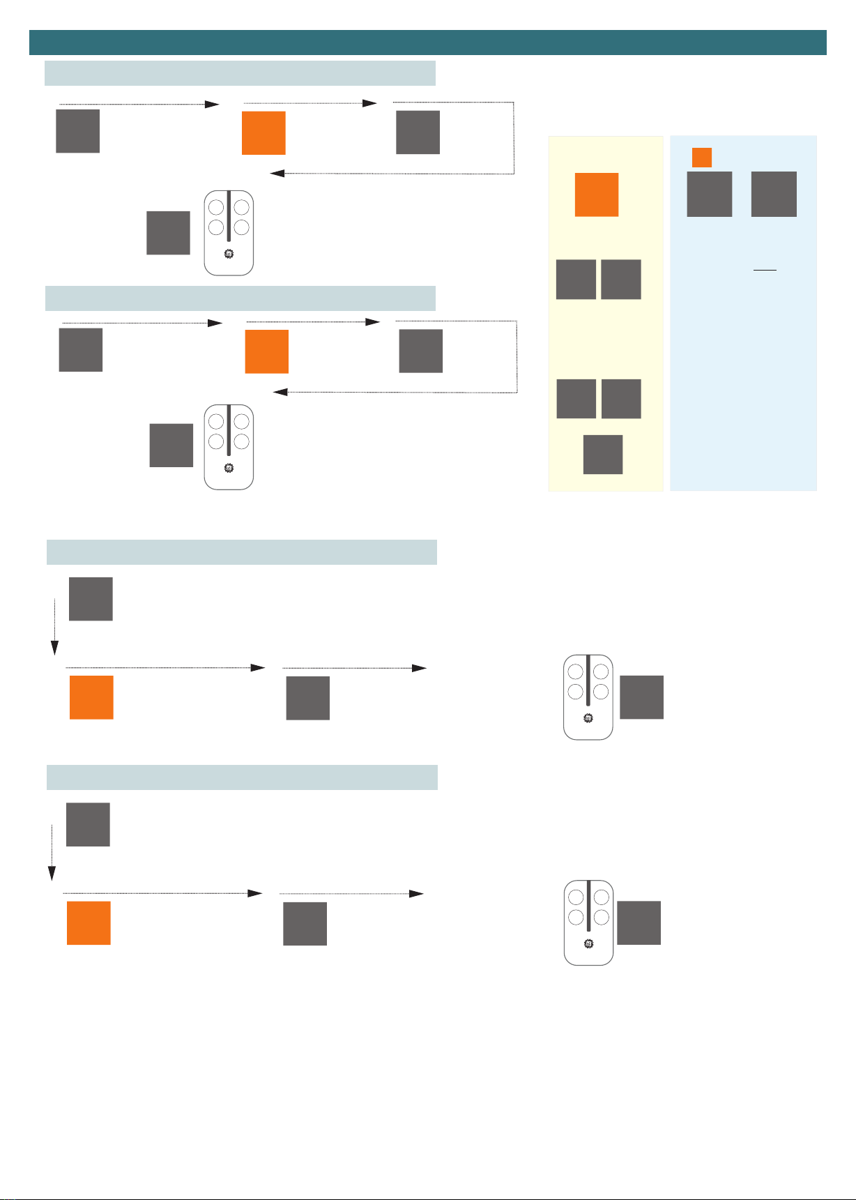
Remote Learning
From the standby screen
press the MODE button
once
From the standby screen
press the MODE button
once
Cycle to Lc and press
MODE
Cycle to Lc and press
MODE
Cycle to c3
Cycle to c4
The display will also show
you the enrolled position it
has been stored in the
memory, this can be noted
incase you wish to delete a
specific remote later.
The display will also show
you the enrolled position it
has been stored in the
memory, this can be noted
incase you wish to delete a
specific remote later.
Press the button you
wish to use on the
remote
Press the button you
wish to use on the
remote
–-
–-
Lc
Lc
c3
c4
9
12
1
1
2
2
3
3
4
4
C3 Driveway Light Learning
C4 Remote STOP command Learning
From the standby
screen press the SET
button once
From the standby
screen press the SET
button once
Cycle to Lc and
press SET
Cycle to Lc and
press SET
Cycle to c 1
Cycle to c 2
The display will also show you the enrolled position
it has been stored in the memory, this can be
noted incase you wish to delete a specific remote
later.
The display will also show you the enrolled position
it has been stored in the memory, this can be
noted incase you wish to delete a specific remote
later.
Press the button you wish to use on the remote
Press the button you wish to use on the remote
–-
–-
Lc
Lc
c1
c2
3
6
1
1
2
2
3
3
4
4
C1 Command Learning
C2 Command Learning
OPEN
OPEN
/STOP/
CLOSE
OPEN
N/A
Ped. OPEN
/STOP/
CLOSE
CLOSE
Lc
c 1 c2
Remote
Channels
oc oA
cd
Operating Logic
St At
oL
Residential
Commercial &
Industrial
Automation Systems
Australia
B
D
A
C
Automation Systems
Australia
B
D
A
C
Automation Systems
Australia
B
D
A
C
Automation Systems
Australia
B
D
A
C
Page 16
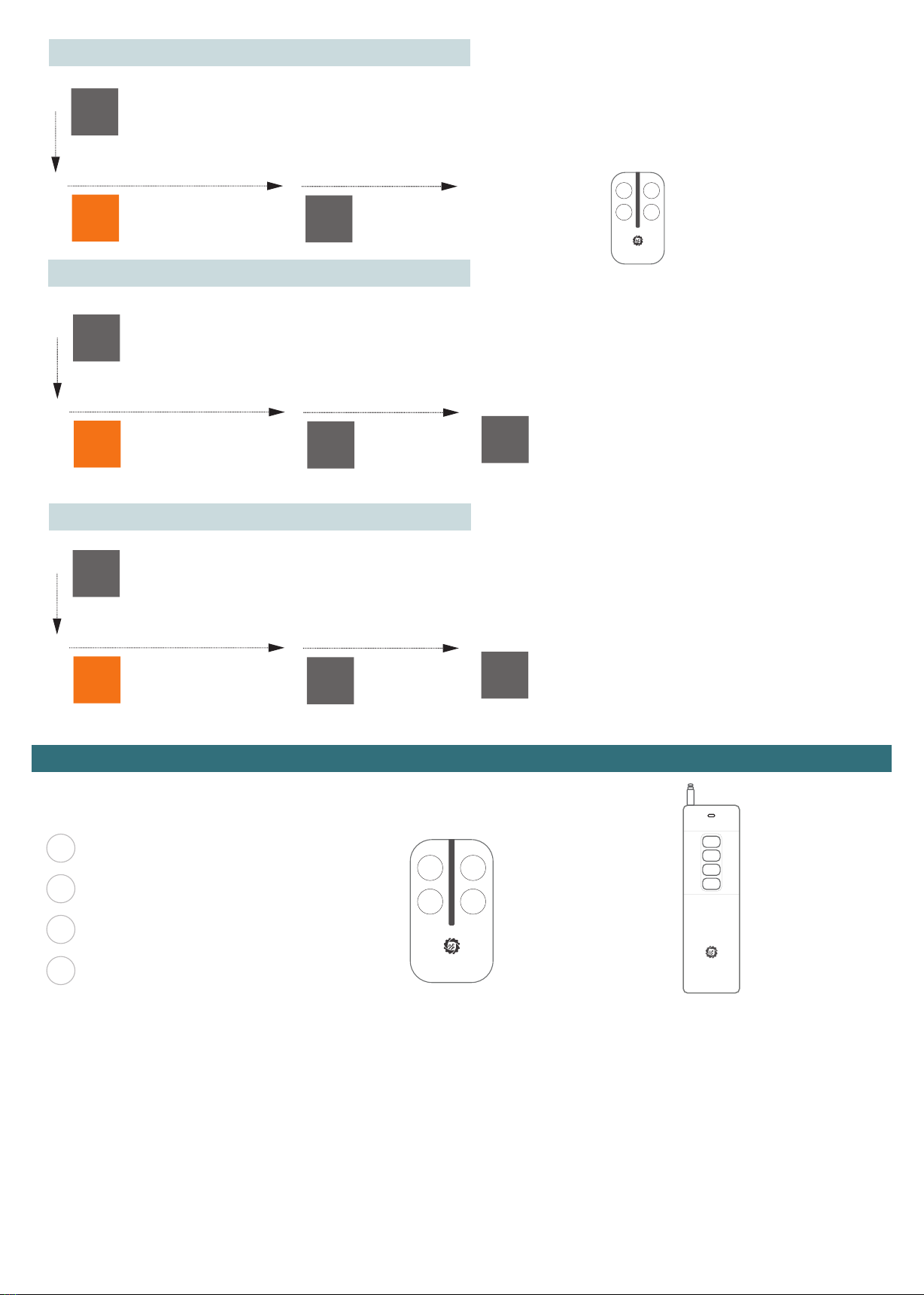
From the standby screen
press the MODE button
once
From the standby screen
press the MODE button
once
From the standby screen
press the MODE button
once
Cycle to Lc and press
MODE
Cycle to Lc and press
MODE
Cycle to Lc and press
MODE
Cycle to rn and
press MODE
Cycle to rA and
press MODE
Cycle to rt
Cycle to the enrolment
number you wish to delete
and press MODE
Cycle to YS and press MODE
to confirm deleting all
remotes
OR
Cycle to nt to cancel
Press the button on the
remote you wish to
delete
–-
–-
–-
Lc
Lc
Lc
rn
rA
rt
04
YS
1
1
1
2
2
2
3
3
3
4
4
4
Delete by remote button
Delete by enrollment number
Delete entire memory
COperate a garage door, driveway light etc.
BOperate Pedestrian Open - Stop - Close
(also stops the automatic closing timer if pressed during the countdown)
AOperate this Gate Open - Stop - Close
(also stops the automatic closing timer if pressed during the countdown)
DOperate another Gate Open - Stop - Close
(also stops the automatic closing timer if pressed during the countdown)
Remote Usage
Automation Systems
Australia
A
B
C
D
Maximum Clear Line
of Sight 800 Metres
Operating Distance
STX4L
Automation Systems
Australia
B
D
A
C
Maximum Clear Line
of Sight 100 Metres
Operating Distance
STX4K
Automation Systems
Australia
B
D
A
C

Page 17
Automation Systems
Australia
B
D
A
C
Identify the enrollment Number
Wireless Keypad Learning
From the standby Screen press each button on the remote INDIVIDUALLY, the number displayed on the screen upon each button press is
the enrollment number, one remote MAY have multiple enrollment numbers based on the paired features
–- –-
05 06
Button is enrolled as
05
Button is enrolled as
06
No Response, Not
Enrolled
No Response, Not
Enrolled
From the standby screen
press the MODE button
once
From the standby screen
press the MODE button
once
Cycle to Lc and press
MODE
Cycle to Lc and press
MODE
Cycle to c 1
Cycle to c2
The display will also show
you the enrolled position it
has been stored in the
memory, this can be noted
incase you wish to delete a
specific remote later.
The easist way to pair a keypad is to take it to the gate controller BEFORE installing onto the post or fence. The installation steps below
detail the procedure using the default codes. It is suggested to change the codes AFTER completing the procedure and testing using
the default code.
Default code 1111= Channel 1 of Keypad, Default code 2222= Channel 2 of Keypad
The display will also show
you the enrolled position it
has been stored in the
memory, this can be noted
incase you wish to delete a
specific remote later.
Type 1111
Type 2222
–-
–-
Lc
Lc
c1
c2
1 1
12
1
1
2
2
3
3
4
4
Operation Command Learning
Pedestrian Gate
From the standby screen
press the MODE button
once
Cycle to oL and
press MODE
For residential homes
select At
For apartments,
complexes, industrial
see Operating Logic
Options Page 10
To set the time cycle to SP
01= Immediate Close
2-299= Delayed automatic
Closing Time by the set value in
Seconds
DEFAULT IS 10 Seconds
once complete
cycle to EH to
return to standby
–-
oL At
1
2345
SP EH
Setting the Automatic Close Timer
Display example up to 99 Seconds Display example GREATER than 99
Seconds and up to 199 Seconds
Display example GREATER than 199
Seconds and up to 299 Seconds
9.9.
99.
99

Page 18
From the standby screen
press the MODE button
once
Cycle to dn and press MODE
Cycle to o1 and HOLD MODE, whilst holding set it will OPEN and It will
stop on the limit switch, release the MODE Button.
* IF the gate does NOT stop on the limit switch, or too early see “Troubleshooting LS” below.
*If the gate Closes instead of Opening see “Troubleshooting MP” below.
Cycle to c2 and
HOLD set, whilst holding set it will CLOSE and It will
stop on the limit switch, release the MODE Button.
IF the gate does NOT stop on the limit switch see
“Troubleshooting LS” below.
Cycle to EH to return to
previous menu
–- dn
o2 c2
EH
1
34
2
The purpose of motor testing is to identify the correct operating procedure before the time travel calibration. The information that can be gained from
the motor test is if the motors are wired:
a) Correct polarity meaning they operate in the correct direction according to the control board.
b)The limit switches have been correctly set for the OPEN and CLOSED position. This test can be repeated an unlimited amount til all is set correctly.
Troubleshooting MP
If the gate(s) close whilst using the open feature this is easily resolved and must be rectified prior to moving forward.
1. Return to Standby
2. Go to the Advanced Menu
3. go to Gd Gate Direction Menu
4. Select the appropriate Direction being rh for Right Hand Opening and LH for Left hand opening
5. Restart the Motor testing procedure
Troubleshooting LS
If the gate(s) travel past the desired stop point OR stops too early the limit switch stiker is mis-configured and will need to be adjusted/set.
1. Confirm which of the limit switch metal striker plates is not set correctly (open limit/close limit)
2. Adjust /install the relevant limit switch striker.
NOTE: Safety Inputs are disabled during this stage
Motor Test Mode
Table of contents


