Vinotemp WINE-MATE WM-2500SSOWC Installation guide

-1-
Important Safety Information
WARNING
To avoid the risk of electrical shock, property damage, personal injury, or death:
•The power cord must be plugged into a 3-prong grounding type wall
receptacle, grounded in accordance with the National Electrical Code,
ANSI/NFPA 70 –latest edition and local codes and ordinances.
•It is the personal responsibility of the consumer to have a proper 3-prong wall
receptacle installed by a qualified electrician.
•DO NOT, UNDER ANY CIRCUMSTANCES, REMOVE THE POWER CORD
GROUNDING PRONG.
•A separate adequately fused and grounded circuit should be available for this
appliance.
•Do not remove any grounding wires from individual components while servicing
unless the component is to be removed and replaced. It is extremely important
to replace all grounding wires when components are replaced.
WARNING
ELECTRICAL SHOCK HAZARD
•Disconnect electrical supply from appliance before servicing.
•Replace all panels before operating.
•Failure to do so could result in death or electrical shock.

-2-
Table of Contents
Cellar Construction Guide 3
Features & Specifications 4
Temperature & Humidity 6
Care Guide 10
User’ Troubleshooting 11
Installer’s Instructions 14
Electrical Wirings 25
Warranty------------------------------------------------------------------26

-3-
Cellar Construction Guide
This is only a guide and shall be considered as the minimum requirements.
All interior walls, ceilings and floors shall have a vapor barrier and a minimum of
R13 insulation. All exterior walls and ceiling shall have a vapor barrier and a
minimum of R19 insulation. The vapor barrier shall be installed on the warm side
of insulation. All joints, door frames, electrical outlets or switches and any pipes
or vents that go through the cellar shall be sealed to prevent air and moisture
leaking into the cellar. Concrete, rock, and brick are not insulations or vapor
barriers. Doors shall be of a minimum size, insulated to at least R13 and tightly
sealed with high quality weather stripping. Be sure to seal the bottom of the door
and fill gap between the door’s frame and wall before installing the cap molding.
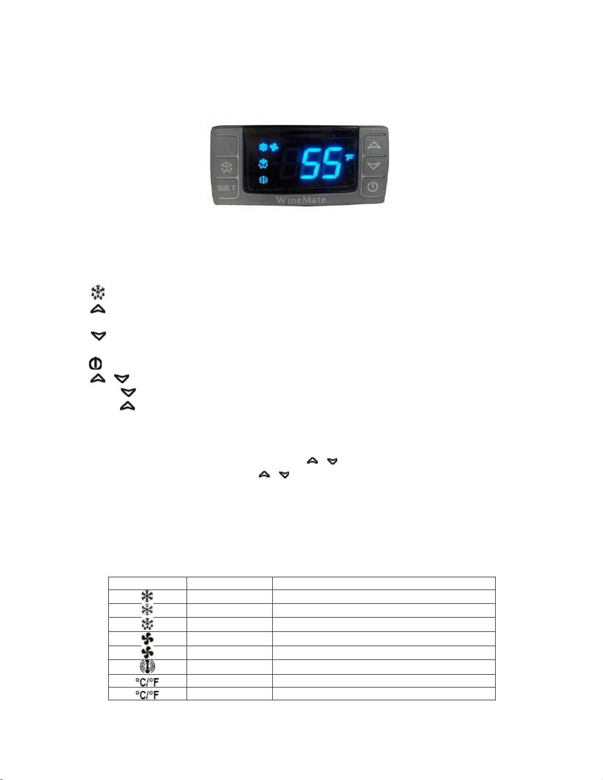
In order to maintain 55 °F in the wine cellar, the ambient temperature surrounding
the cellar shall not exceed the temperature of the cellar by morethan 25 °F.
No cellar walls shall receive direct sun or strong wind.
Lighting shall be of low wattage, with a timer to insure lights are not left on when
the cellar is not occupied.
The cooling system will not be able to maintain the proper temperature if fresh
moisture-laden air is constantly being introduced to the cellar. Symptoms of this
condition are; cooling unit runs all the time with only a slight reduction in
temperature and/or water overflows from the cooling unit. Because of the
temperature difference between the inside and outside, very small cracks can
allow large amounts of outside air to enter into the cellar. Please be aware that
moisture can pass through solid concrete, paint and wood. Often a newly
constructed cellar contains fresh wood, paint, concrete and other building
materials. These materials contain large amounts of moisture. When placed into
operation in this type of environment, the system will work harder to remove this
extra moisture resulting in increased “run” time.

-4-
Features and Specifications
•
WM-2500~4500SSOWC split water-cooled through-ceiling cooling systems are
designed to provide a cold environment between 50~65 °F with a humidityrange within
50~70% RH for a properly insulated wine cellar.
•
These temperature and humidity ranges are optimized for long term storageof wine
like that in natural caves.
•
SSO evaporator units can be installed through the ceiling outside a wine cabinet or room.
The evaporator units are designed to maximize storage space.
•
SSOWC cooling systems consist of a remote condensing unit and an evaporator unit
and they are connected by a liquid line and an insulated suction line.
•
SSOWC condensing units are water cooled so that exhaust ventilation is not needed.
•
SSOWC condensing units can be located away from the wine cellars up to 75ft so that
noise and compressor vibration are isolated.
Fig. 1 SSOWC Split Water-Cooled Through-Ceiling Cooling System

-5-
CAUTION
The condensing unit must operate above 32 °F ambient
temperature
NOTE
The cooling capacity is determined under 55°F cellar
temperature, 75°F cellar ambient temperature and 90°F
condensing unit ambient temperature, with R13 interior and R19
exterior insulations. Higher ambient temperatures or lower
insulations will cause reducing capacity and the cellar
temperature may not be maintained at 55°F.
The specifications are listed as follows:
Model No.
Capacity (Btu/h) / Airflow (CFM)
Max Cellar Size (cu ft)
WM-2500SSOWC
2500 / 220
250
WM-4500SSOWC
4500 / 335
1000
For further info, see Fig. 3~7.

-6-
Temperature and Humidity
1. The controller
Fig. 2 TEMPERATURE CONTROLLER
1) Keys
SET: To display set-point; in programming mode it selects a parameter or confirms
an operation.
: To start a manual defrost.
: To see the maximum stored temperature; in programming mode it browses
the parameter codes or increases the displayed value.
: To see the minimum stored temperature; in programming mode it browses
the parameter codes or decreases the displayed value.
: To turn on/off the power to the unit.
+ : To lock/unlock the keypad.
SET+ : To enter in the programming mode.
SET+ : To return to the temperature display.
2) Lock and unlock the keys
To lock the keys, press up + down keys + until POF is displayed; to unlock
the keys, press up + down keys + until PON is displayed.
3) Display
During normal operating conditions, the display shows the value measured by
the air temperature probe. In case of active alarm, the temperature flashes
alternately to the code alarm. The LED functions are listed as follows.
LED
MODE
FUNCTION
ON
Compressor enabled
Flashing
Anti-short cycle enabled
ON
Defrost enabled
ON
Fan enabled
Flashing
Fan delay after defrost enabled
ON
Alarm occurring
ON
Temperature measuring unit
Flashing
Programming mode

-7-
4) Alarm Signals
The alarm codes are described as follows.
MESSAGE
CAUSE
FUNCTION
P1
Temperature probe
faulty
Compressor switching to Con and
CoF
HA
High temperature
alarm
Probe temperature ALU higher than
the
setting temperature; Outputs
unchanged
LA
Low temperature
alarm
Probe temperature ALL lower than
thesetting temperature; Outputs
unchanged
CA
External alarm
All outputs off
Probe alarms P1”, start a few seconds after the fault in the related probe; they
automatically stop a few seconds after the probe restarts normal operation.Check
connections before replacing the probe. Temperature alarms “HA”, “LA”
automatically stops as soon as the temperature returns to normal value. Alarm
“CA” (with i1F=PAL) recovers only by switching off and on the instrument.
2. Temperature Setting
•
Set the temperature at 55 °F for the optimum aging of wine
•
On initial start-up, the time required to reach the desired temperature will
vary, depending on the quantity of bottles, temperature setting andsurrounding
temperature.
•
Allow 24 hours to stabilize the temperature for each new temperature setting
operation
3. How to see temperature set-point
1) Press and immediately release the SET key, the display will show the set-point
value.
2) Press again and immediately release the SET key to display the probe value.
4. How to change the set-point
1) Press and hold the SET key until the “°C” or “°F” LED starts flashing and the
set-point is displayed.
2) Press the up/down keys / to change the set-point value within 10 sec.
3) Press the SET key again to store the new set-point value.
NOTE
The unit turns on at set-point Set plus regulation differential Hy after
anti-short cycle AC has elapsed; the unit turns off at set-point Set.

-8-
5. Manual Defrost
Press and hold the defrost key until defrost starts. The defrost indicator will be
on.
6. Parameter Programming
1) Press and hold the SET + keys until the “°C” or “°F” LED starts flashing,
then release the keys.
2) Press and hold again the SET + keys until the Pr2 label is displayed, then
release the keys. The first parameter Hy will be displayed.
3) Press up/down keys / to scroll to the required parameter within 10 sec.
4) Press the “SET”key to display its value.
5) Use up/down keys to change its value within 10 sec.
6) Press “SET”to store the new value and the display will flash 3 times.
7) To exit: Press SET + or wait 15sec without pressing a key.
PARAMETER
DESCRIPTION
DEFAULT VALUE
Set
set-point (°)
55
Hy
temperature regulation differential
(°)
4
AC
anti-short cycle delay (min)
10 (hidden)
Con
compress on with probe faulty (min)
15
CoF
compress off with probe faulty
(min)
30
CF
temperature unit (°F/ °C)
F: Fahrenheit
rES
display resolution
in: integer
dLy
temperature display delay (min)
1
ot
probe calibration (°)
0
LS
minimum set-point (°)
50
US
maximum set-point (°)
65
idF
defrost interval time (hour)
12
MdF
defrost endurance time (min)
30
ALC
temperature alarm type
rE: relative to set-point
ALU
high temperature alarm (°)
10
ALL
low temperature alarm (°)
10
AFH
alarm recovery differential (°)
5
ALd
temperature alarm delay (min)
60
dAO
temperature alarm delay on startup
(hr)
23
SAA
heater set-point (°)
40
SHy
heater regulation differential (°)
4
FSU
fan action
Std
FnC
fan operating mode
C-n: on with compressor & off during
defrost
Fon
fan on with compressor off (min)
0
FoF
fan off with compressor off (min)
15
NOTE
Depending on the controller, not all parameters are available.

-9-
7. How to calibrate the air probe
If the actual cellar temperature differs from the setting temperature, set parameter
ot = actual cellar temperature minus set-point.
8. How to adjust defrost settings
In case there is excessive frost, the parameters FnC = C-y, idF = 4 and MdF =
20 can be used to avoid frost.
9. How to adjust the humidity
The parameter Fon is used to adjust the humidity in the wine cellar. Higher Fon
results in higher relative humidity. Use a separate hygrometer to monitor the
humidity.
10. How to set alarm call
1) Speech notice will be sent to your phones when the cellar temperature is ALU
higher or ALL lower than the set-point Set.
2) In order to test the call function, set parameters Ald = 0 and dAO = 0. After
testing, set Ald = 60 and dAO = 23.
11. How to set cellar heater
The heater turns on at SAA minus Shy; the heater turns off at SAA.
NOTE
Use a forced air heater to warm up the wine cellar.
If there is a thermostat on the heater, bypass it or set the
thermostat at the highest level.
If the heater runs more than 10 A current, use a 120VAC coil
contactor.

-10-
Care Guide
In general, always unplug system or disconnect power while doing care.
1. Condenser Water Line Cleaning
•
To clear any sediment that may accumulate, the water regulating valve may
be manually flushed.
•
Insert screwdrivers under both sides of the valve spring guide and lift upwards
to flush.
2. Condensate Removing
•
Remove the excessive condensate if it is accumulated in the wine cellar at
high humidity conditions.

-11-
User’s Troubleshooting
This Troubleshooting Chart is not prepared to replace the training required for a
professional refrigeration service person, not is it comprehensive.
Complaint
Possible Causes
Response
1. Unit not running
a. Power cord not plugged
b. No power from supply
c. Incorrect or loose wirings
d. Low voltage
e. Setting higher than
ambienttemperature
f. Waiting for cut-in
g. Defrost light blinking
h. Compressor light blinking
i. Defective controller
a. Check power cord
b. Check receptacle and fuses
c. Check all wirings and connections
d. Contact an authorized electrician
e. Lower temperature setting
f. Wait
g. Unit is under defrost mode
h. Unit is under anti-short cycle delay
i. Call service for diagnosis
2. Unit not
startingand
temperature
rising high
a. Anti-short cycle
a. Reset AC
3. Temperatur
efluctuating
a. Air probe
a. When using an air probe, the wine bottle
temperature is mainly controlled by the
average air temperature. If the set-
point is 55°F with the differential 4F, the
cooling unit turns on at 59°F of air
temperature (It may be higher than
59°F if it is in anti-short cycle or defrost)
and turns off at 55°F of air temperature.
The average airtemperature is 57°F,
and then the wine temperature is
around 57+/- 0.5°F. The air is light
enough to change so quickly that it
maintains relatively constant average
temperature that would prevent wine
bottle temperature from fluctuating.
4. Temperature
high, unit
stopping
andstarting
normally
a. Temperature setting high
a. Lower the setting
5. Temperature
high, unit
stopping and
starting with
short
running
time
a. Air probe touching the
evaporator coil, displaying
temperature ok
b. Air probe in cold-air supply,
displaying temperature ok
c. Failed controller and probe
a. Move the air probe away from the
evaporator
b. Move the air probe away from the
cold-air supply
c. Call service for diagnosis
6. Temperatur
ehigh or
not cooling
andrunning
continually
a. Improper cellar insulation &
seal
b. Cellar too large
c. Malfunctioning fans
d. Evaporator airflow
a. Check insulation, gasket and door
opening
b. Check for excessive size
c. Check for evaporator fans
d. Check for air restrictions, air short-
circulation, grille directions

-12-
e. Dirty Condenser
f. Improper condenser cooling
g. Iced evaporator
h. Refrigeration system restriction
i. Refrigerant leak
j. Undercharge or overcharge
k. Failed components
e. Clean condenser
f. Check for water flow
g. Defrost and reset temperature
h. Call service
i. Call service
j. Call service
k. Call service
7. Unit running too
long
a. Improper cellar insulation & seal
b. Cellar too large
c. Dirty Condenser
d. Improper condenser cooling
a. Check insulation, gasket and door
opening
b. Check for excessive size
c. Clean condenser
d. Check for water flow
8. Temperature
high,
compressor
stopping and
starting but
very short
running time
a. Failed components
b. Improper condenser cooling
c. Overcharge of refrigerant
d. Discharge or suction
pressuretoo high
a. Check compressor windings, start
relay and overload protector.
b. Check for condenser water flow
c. Call service for removing refrigerant
d. Call service for information
9. Evaporator fan
running too
long
a. Post-compressor fan
running
mode for humidity modulation
a. Reset FON
10. Evaporator fan
running but
condensing unit
not
running
a. Incorrect or loose wirings
b. Failed components
c. Low refrigerant
a. Check all wirings and connections
b. Check start relay, start capacitor,
overload protector, compressor.
c. Call service
11. Temperature
low
a. Low temperature setting
b. Low ambient temperature
c. Air probe fault
d. Temperature controller fault
a. Raise the setting
b. Move to another location
c. Check probe connections or changea
new one
d. Change a new one
12. Evaporator
freezing up
a. Evaporator air flow restriction
b. Improper condenser cooling
c. Not stopping due to air leak,
high ambient temperature or
low temperature setting
d. Defective controller or probe
e. Low ambient temperature
f. Initially working then stopping,
moisture in the system
g. Refrigerant low or leaking
h. Expansion valve blockage
a. Check for fans and CFM
b. Check for water flow
c. Check for seal, door opening, ambient
temperature andtemperature setting
d. Check for controller and probe
e. Change defrost settings
f. Call service
g. Call service
h. Call service
13. Water leak in
wine cellar
a. Air leak in the wine cellar
causingexcessive condensate
b. High humidity causing
excessivecondensate
c. Evaporator air flow restriction
d. Drain restricted or unit not
level,and water overflowing
e. Drip tray leak (No overflow but
leak)
a. Check for air leak
b. Use drain line
c. Check supply air flow or air TD
d. Clean the drip tray and drain line
e. Seal the leak using silicone sealant
14. Excessive
condensate in
wine cellar
a. Air leak in the wine cellar
causingexcessive condensate
b. High humidity causing
excessive
a. Check for any air leak
b. Use drain line

-13-
condensate
c. Drain restricted
c. Clean the drip tray and drain line
15. Condensate
inside ducts
a. Drain line restricted
b. Continually running not
stopping
c. Too cold supply air
a. Check for drain
b. raise temperature setting or
increase defrost
c. Increase air flow or raise
temperature setting
16. Condensate
outside
ducts
a. Duct not insulated
b. High humidity
c. Too cold supply air
a. Check for insulation
b. Use dehumidifier
c. Increase air flow or raise
temperature setting
17. Circuit tripping
a. Incorrect fuse or breaker
b. Incorrect wirings
c. Failed components
a. Check for proper fuse or breaker
b. Check for wirings and connections
c. Call service
18. Noisy
operation
a. Mounting area not firm
b. Loose parts
c. Compressor overloaded due
toimproper condenser cooling
d. Defective components
a. Add support to improve installation
b. Check fan blades, bearings,
washers, tubing contact and loose
screws.
c. Check for water flow
d. Call service for checking internal
loose, inadequate lubrication and
incorrect wirings

-14-
Installer’s Instructions
WARNING
Do not use a ground fault interrupter (GFI).A
dedicated circuit is required.
WARNING
•Always check wiring harness connections before initiating any test procedures.
•Disconnect electric power from the appliance before performing any
maintenance or repairs.
•Voltage checks should be made by inserting meter proves beside the wires in
the connector blocks with the electric power source on and the connector block
plugged in.
•Resistance checks should be made on components with the electric power off
and the connector block disconnected.
Federal law requires that WINE~MATE split cooling systems be
installed by an EPA certified refrigeration technician.
1. General Instructions
WINE~MATEsplit system is shipped as components and is ready for use only after
a certified refrigeration technician has properly installed the system. Proper
installation is critical. Vinotemp can only warrant the quality of the components.
The installation and proper operation of the system must be warranted by the
installer. Installation of the system must be done in accordance with all state and
local building and electrical codes.
The condensing unit and evaporator unit are connected by a liquid line and an
insulated suction line that are supplied by the installer. These lines must be
properly sized for the distance between the two units. After the units and lines
are connected, the system must be checked for restriction, pressurization and leak.
Then the system must be evacuate and charged with refrigerant. Refrigerant
amount will vary depending on the length of line set.
Parts included:
Temperature Controller
Evaporator Unit (liquid line solenoid valve and expansion valve are installed)
Condensing Unit (pressure control, water regulation valve, discharge and suction
valves and installed)
Liquid Filter
LiquidIndicator

-15-
Parts not included:
Liquid line copper tubing
Suction line copper tubing
Water lines
CAUTION
Liquid and suction line locations may differ from that they areshown
below, please check on the units for proper installations.
NOTE
To prepare rough-in, leave minimum 4” clearances for electrical
wiring and refrigeration piping.
Model No.
Evap Unit (“)
L x W x H –L1
x W1
Cond Unit
(“)L x W x
H
Electrical Rating
Evap Unit /
Cond Unit
Min Circuit
Ampacity(A)
Weight (lb)
Evap Unit / Cond
Unit
WM-
2500SSOWC
WM-25SFCO
48 x 12 x 8-1/8
–
45 x 9-1/8
WM-
250SCUR-
WC
24 x 18 x
18
115V-60HZ-1A
115V-60HZ-5A
20A
34 / 40
WM-
4500SSOWC
WM-45SFCO
48 x 24 x 8-1/8
–
45 x 21-1/8
WM-
450SCUR-
WC
24 x 18 x
18
115V-60HZ-1A
115V-60HZ-6A
20A
63 / 60
Fig. 3 Temperature Controller (4.5”L X 4.5”W X 3.75H)

-16-
Fig. 4 WM-25~45SFCO Evaporator Unit
Fig. 5 WM-250~450SCUR-WC Condensing Unit

-17-
Fig. 6 WM-Liquid Filter Fig. 7 WM-Liquid Indicator
2. Temperature Controller and Air Probe Location
1) The temperature controller can be mounted either inside or outside the wine
cellar, but the air probe must be located inside.
2) The air probe shall be located in the wine cellar 5 ft above the floor or the air
return area, but it shall not be located in the air supply area or other areas
where air is not circulated.
3) Air probe can be pulled out of the temperature controller up to 5 ft. If additional
wires are necessary, 18 gauge wires may be used to extend the airprobe.
3. Evaporator Unit Location
1) The WM-25~45SFCO evaporator units shall be installed above the ceiling
with the supply air at one side and return air at the other side. It shall not be
exposed to temperatures higher than 85 °F. Make a cutout L1 x W1.
2) Air supply shall be unobstructed minimum 12”; air return shall be unobstructed
minimum 6”.
3) There is a gravity drain system, so the unit shall be installed level or with a
slight slope downward the drain connection and the drain line shall be installed
slope down toward the drain.
If rise-up is necessary, a condensation pump must be used.
4. Condensing Unit Installation
1) Condensing unit shall be elevated to avoid possible flooding and shaded from
direct sun. The location shall not be subject to freezing temperatures.
2) Water must be supplied to WM-250~450SCUR-WC at all times during
operation, with the maximum outlet temperature of 120 °F. A sufficient amount
of water must be provided for constant head pressure and proper cooling, but
excessive water flow will cause the unit working inefficiently.
3) The maximum permissible water pressure is 150 PSIG. If water pressure is
excessive, a pressure reducing valve must be used to reduce water pressure.
4) Service valve operation
5. Refrigeration Piping and Leak Testing

-18-
NOTE
The line connector sizes of liquid filter and indicator, the valve
connector sizes of condensing unit or the line connector sizes of
evaporator unit may not be the same as the listed refrigeration line
sizes.
If the condensing unit is installed above the evaporator unit, usethe
suction line one size smaller.
Expansion and solenoid valves have been installed on the liquid line
in the evaporator unit.
The line sizes and refrigerant charges are listed as follows.
Model No.
Equivalent
Line Set
Liquid
Line
Suction
Line
Drain Line
Recommended
Initial Charge
WM-
2500SSOWC
<= 75 FT
1/4" OD
3/8” OD
1/2” MPT
R134a / 19 OZ
WM-
4500SSOWC
<= 75 FT
1/4" OD
1/2” OD
1/2” MPT
R134a / 26 OZ
1) The piping starts from condensing unit’s receiver discharge valve liquid
filter liquid indicator liquid line to evaporator unit’s liquid line connection
(assembled with solenoid valve and expansion valve) suction line connection
insulated suction line to condensing unit’s suction valve.
2) If the line set exceeds 75 ft long, use both inverted U trap and suction
accumulator to prevent liquid from flooding back to the compressor.
3) If the condensing unit is located below the evaporator unit, use inverted U
trap to prevent liquid from flooding back to the compressor. If the elevation
difference is more than 10 ft, use both inverted U trap and suction accumulator.
4) If the condensing unit is located more than 10 ft above the evaporator unit, use
U trap to aid oil returning to the compressor.
5) Complete pipe brazing, check solenoid valve and expansion valve restrictions
and perform leak testing.
6) Hook up the drain line and check if water drains.
6. Water Piping
If a water pump is used, install it before the water inlet so that the condenser
cooling water is fed from the discharge side of the pump.
Model No
Condensing Unit
Water Flow (75°F
inlet, gal/min)
Water-in
Connection
Water-out
Connection
Water
Pressure Drop
(PSI)
WM-2500SSOWC
WM-250SCUR-WC
0.2
3/8” FPT
1/2" ODF SOLDER
0.2
WM-4500SSOWC
WM-450SCUR-WC
0.4
3/8” FPT
1/2" ODF SOLDER
0.2
7. Connecting Electrical Wires
Connect all electrical components using the wiring diagrams in accordance with
all state and local codes.

-19-
8. Evacuating, Charging and Starting the System
1-Manifold High or Low Pressure Hose; 2-Receiver Discharge or
Compressor Suction Port; 3-Liquid or Suction Line; 4-Pressure Control;
BACK POSITION FRONT POSITION MIDDLE POSITION
Fig. 8 ROTALOCK Valve Operation
BACK POSITION FRONT POSITION MIDDLE POSITION
Fig. 9 Base Valve Operation
Back Position: Normal operation, manifold port is closed.
Front Position: Storage operation, liquid or suction line connection is closed.
Middle Position: Installation operation, all ports are open.
NOTE
The recommended initial charges are used for reference only,always
use the superheat, subcooling and pressure readings to charge
refrigerant properly.
1) Turn both discharge and suction valves in the middle positions.
2) Connect the manifold high or low pressure hose to the discharge or suction
valve and connect it to a vacuum pump.
3) Open the manifold high and low pressure valves to evacuate the system.
4) Close the manifold high and low pressure valves and switch it to a charging
scale.
This manual suits for next models
1
Table of contents
Other Vinotemp Air Conditioner manuals