Viola Systems ESERV-10 User manual

ESERV-10 User’s Manual
Version 2.2, June 2003

User’s Manual
Contents
Contents.............................................................................................................................................. 2
Copyright and Trademark ................................................................................................................... 3
Disclaimer and Revisions.................................................................................................................... 4
Declaration of Conformity ................................................................................................................... 5
Warranty and Safety Instructions........................................................................................................ 6
Specifically Dangerous Places and Places with Particular Risk of Damages .................................... 6
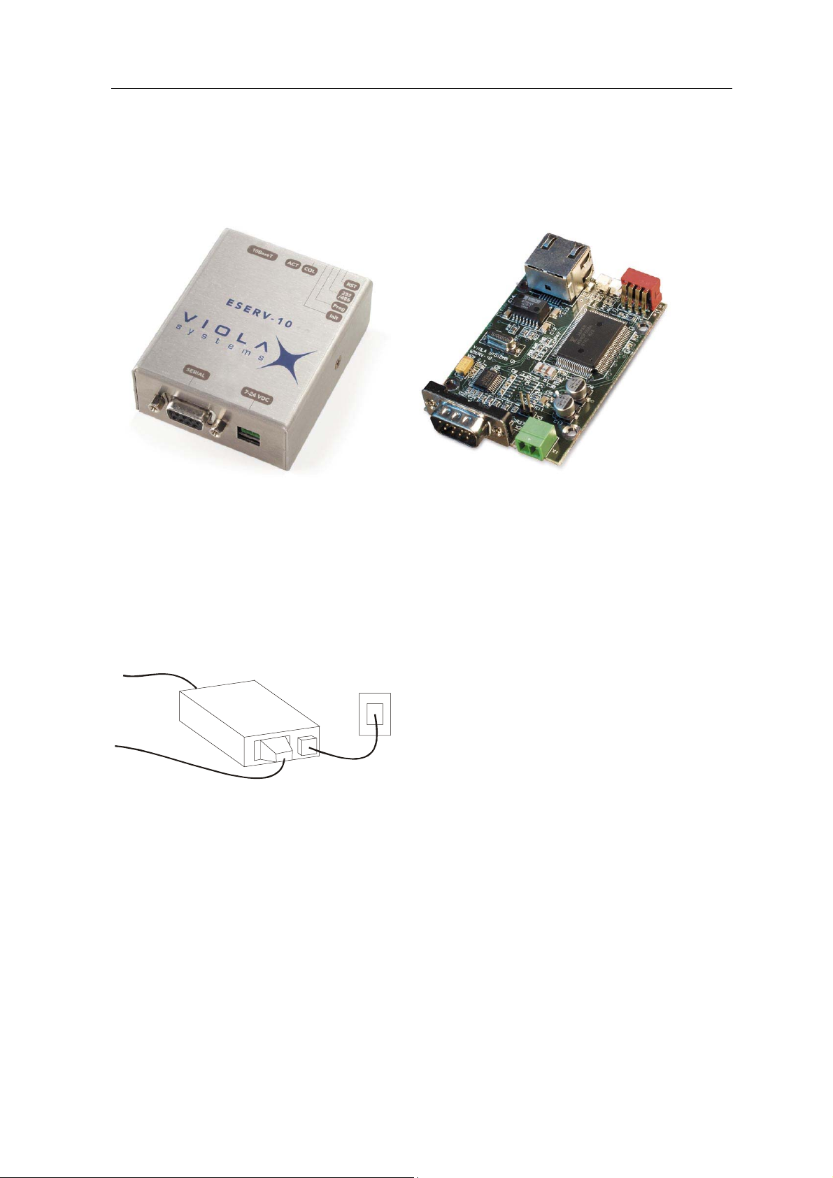
1. Introduction ..................................................................................................................................... 7
Internal Software.................................................................................................................... 8
2. Operation of ESERV-10.................................................................................................................. 9
Connection via Internet to Serial Port.................................................................................... 9
Web Server .......................................................................................................................... 10
3. Connectors and Switches ............................................................................................................. 11
Serial Port (RS-232, RS-422/485 -connector) ..................................................................... 11
Ethernet Connector..............................................................................................................12
DIP Switches........................................................................................................................ 12
LEDs .................................................................................................................................... 13
Power Supply Connector ..................................................................................................... 13
Product Information Label.................................................................................................... 13
4. Getting Started.............................................................................................................................. 14
Installation of the Device......................................................................................................14
Addresses Related to Internetworking................................................................................. 14
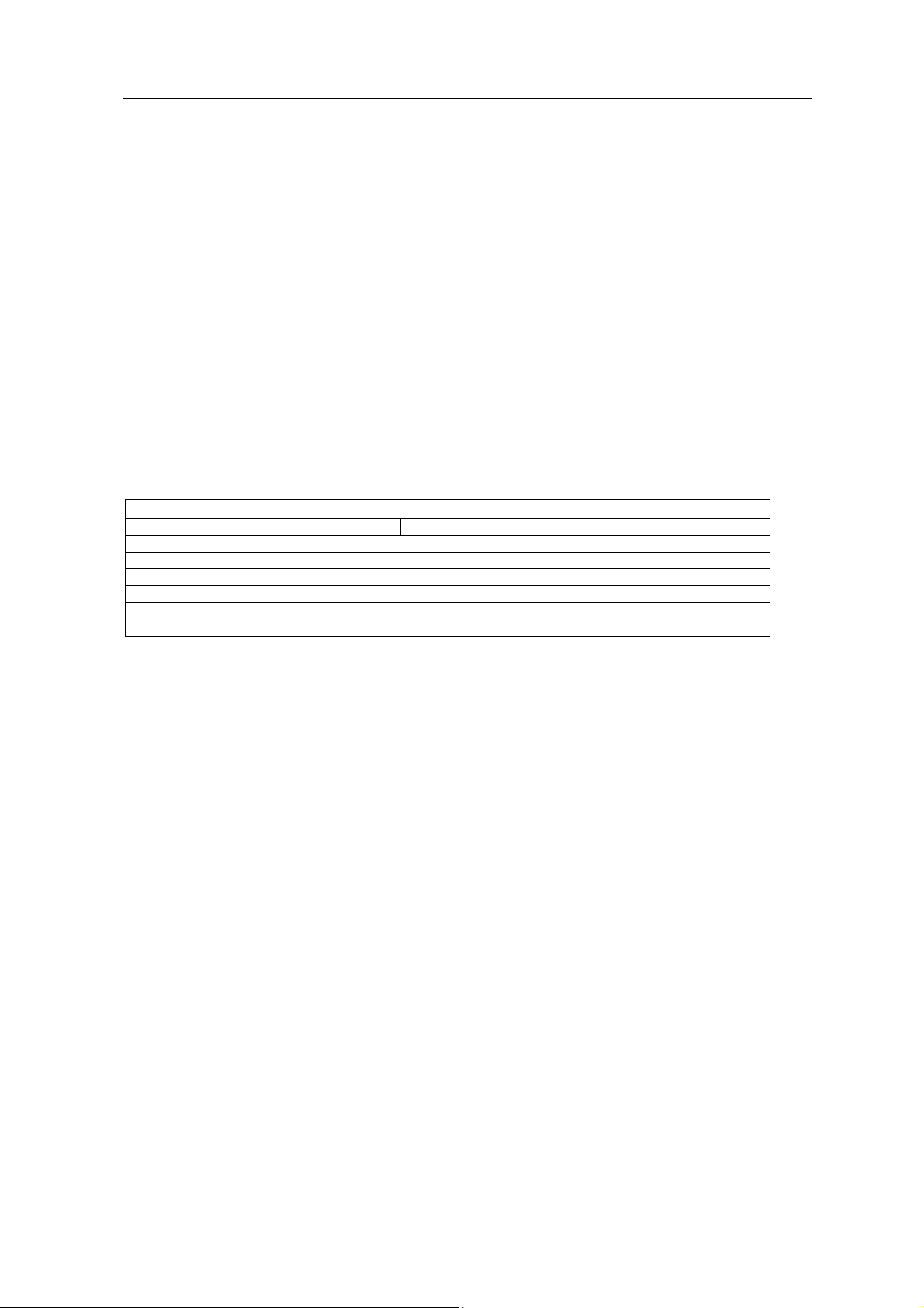
Connect the Device..............................................................................................................15
Install the Viola Configurator................................................................................................ 16
Add a New Device ............................................................................................................... 17
Assign the IP Address and Network Mask .......................................................................... 18
Creating duplicate configuration .......................................................................................... 19
5. ESERV-10 Configuration .............................................................................................................. 20
Configuring Using Viola Configurator .................................................................................. 20
Configuring Using ICMP PING ............................................................................................ 21
Configuring Using Telnet Connection.................................................................................. 22
Configuring Using Serial Port .............................................................................................. 23
6. Constructing and Saving Web Pages........................................................................................... 24
Construction of Web Pages ................................................................................................. 24
7. Features........................................................................................................................................ 25
Transmission Trigger Algorithms ......................................................................................... 25
Security of ESERV-10 ......................................................................................................... 25
E-mail Features.................................................................................................................... 26
COM Port Redirector SW .................................................................................................... 27
Appendix 1 Technical Specifications..................................................................................... 28
Appendix 2 Server Modes of ESERV-10............................................................................... 29
Appendix 3 Key Parameters of ESERV-10 ........................................................................... 30
Appendix 4 Supported AT Commands.................................................................................. 31
Appendix 5 Basics of Internetworking ................................................................................... 34
Appendix 6 ESERV-10 configuration parameters ................................................................. 36
Return Policy..................................................................................................................................... 40
Limited Warranty............................................................................................................................... 41
ESERV-10 2 Viola Systems Ltd.

User’s Manual
Copyright and Trademark
2003 Viola Systems Ltd. All rights to this manual are owned solely by Viola Systems Ltd (referred
to in this user’s guide as Viola Systems). All rights reserved. No part of the contents of this book
may be transmitted or reproduced in any form or by any means without the written permission of
Viola Systems.
Ethernet is a trademark of XEROX Corporation. Windows and Internet Explorer are trademarks of
Microsoft Corporation. Netscape is a trademark of Netscape Communications Corporation. All other
product names used in this manual are the properties of their respective owners and are
acknowledged.
Viola Systems Ltd.
Lemminkäisenkatu 32
FIN-20520 Turku
Finland
E-mail: info@violasystems.com
Technical Support
Phone: +358 2 01 226 226
Fax: +358 2 01 226 220
E-mail: support@violasystems.com
On-line http://www.violasystems.com
ESERV-10 3 Viola Systems Ltd.

User’s Manual
Disclaimer and Revisions
Viola Systems reserves the right to change the technical specifications or functions of its products,
or to discontinue the manufacture of any of its products or to discontinue the support of any of its
products, without any written announcement and urges its customers to ensure, that the information
at their disposal is valid.
Viola software and programs are delivered “as is”. The manufacturer does not grant any kind of
warranty including guarantees on suitability and applicability to a certain application. Under no
circumstances is the manufacturer or the developer of a program responsible for any possible
damages caused by the use of a program. The names of the programs as well as all copyrights
relating to the programs are sole property of Viola Systems. Any transfer, licensing to a third party,
leasing, renting, transportation, copying, editing, translating, modifying into another programming
language or reverse engineering for any intent is forbidden without the written consent of Viola
Systems.
Viola Systems has attempted to verify all information in this manual as of the publication date. We
assume no responsibility for any errors that may appear in this guide. Information in this manual
may change without prior notice from Viola Systems.
Revision History:
10/2002 HW Release 2.1, Preliminary version, released
11/2002 Document Release 2.1a, Preliminary version, released
03/2003 Document Release 2.1b, Preliminary version, released
05/2003 Document Release 2.1c, Preliminary version
06/2003 Document Release 2.2, Preliminary version
ESERV-10 4 Viola Systems Ltd.

User’s Manual
Declaration of Conformity
(according to ISO/IEC Guide 22 and EN 45014)
Manufacturer’s Name:
Viola Systems Ltd.
Manufacturer’s Address:
Lemminkäisenkatu 32, FIN-20520 Turku, Finland
declares that this product:
Product Name:
Device Server
Model Name(s):
ESERV-10 and ESERV-10 OEM
conforms to the following standards:
EMC:
EN 55022 Emission Test (Class A)
1. Radiated Emissions (30-1000MHz)
2. Conducted Emissions (0.15-30MHz)
EN 50082-1 Immunity Test
1. IEC 801-3: Radio Frequency Electromagnetic Field
2. IEC 801-2: Electrostatic Discharge
3. IEC 801-4: Fast Transients, AC Power Ports and Signal cables
Supplementary Information:
“The product complies with the requirements of the Low Voltage Directive 73/23/EEC and
EMC directive 89/336/EEC.”
Warning: This is a Class A product. In a domestic environment this product may cause radio
interference in which case the user may be required to take adequate measures.
Manufacturer’s Contact:
Director of Quality Assurance
Viola Systems Ltd.
Lemminkäisenkatu 32, FIN-20520 Turku, Finland
Phone: +358 (0)2 01 226 226
Fax: +358 (0)2 01 226 220
ESERV-10 5 Viola Systems Ltd.

User’s Manual
Warranty and Safety Instructions
Read these safety instructions carefully before using the product:
Warranty will be void, if the product is used in any way, which is in contradiction with the
instructions given this manual, or if the device server has been tampered with.
The devices mentioned in this manual are to be used only according to the instructions described in
this manual. Faultless and safe operation of the devices can be guaranteed only if the transport,
storage, operation and handling of the devices is appropriate. This also applies to the maintenance
of the products.
To prevent damage both the device server and any terminal devices must always be switched OFF
before connecting or disconnecting any cables. It should be ascertained that different devices used
have the same ground potential. Before connecting any power cables the output voltage of the
power supply should be checked.
Specifically Dangerous Places and Places with Particular
Risk of Damages
The product is not designed to be used in dangerous places including, but not limited to, equipment
monitoring patients, nuclear plants, aircrafts, weapon systems, traffic control devices or for any
other similar purposes with the possibility of risk for life or serious risk for health. Should the product
be used for the above purposes or in connection with any such purpose, Viola Systems shall under
no circumstances have any liability for such use.
Places with particular risk of damages shall include, but not be limited to, factories and similar
production plants, water transport vessels, railways or other similar places in connection with which
the malfunctioning of the product may cause major financial damages. Should the product be used
for purposes mentioned in this section without a prior written permission of Viola Systems, Viola
Systems shall under no circumstances have any liability for such use.
ESERV-10 6 Viola Systems Ltd.

User’s Manual
1. Introduction
This User’s Manual describes the operation of the ESERV-10, ESERV-10S, ESERV-10S Bridge
and ESERV-10 OEM device servers. All devices are referred to in this User’s Manual as ESERV-
10, unless otherwise mentioned.
ESERV-10 is designed to offer transparent connection between a serial device and Ethernet
without the need to modify the existing design of the device. With ESERV-10 manufacturers and
system suppliers can connect their products such as home and industrial automation devices,
measuring devices and sensors through Ethernet to Internet. Devices can be controlled and
monitored using a standard Web browser (Internet Explorer, Netscape Navigator), a Telnet
connection or some other programs with a TCP/IP connection.
ESERV-10
SERIAL
DEVICE
10BASE-T
ETHERNET POWER
SUPPLY
ESERV-10 device servers can be used, for example, in cases of:
•Remote reading of access control and work time monitoring systems
•Software updates and configuration over the Internet
•Motion sensors
•Remote control of display boards
•Global follow-up of systems
•Replacement of serial cable network with ready-made Ethernet network
ESERV-10 7 Viola Systems Ltd.

User’s Manual
ESERV-10 device server works in three different operating modes, each of which put emphasis on
a particular functionality. First, ESERV-10 is able to operate as a serial device server in both server
and client modes. Second, ESERV-10 functions through sending and receiving e-mail by using
SMTP (Simple Mail Transfer Protocol) and POP3 (Post Office Protocol) protocols, either
automatically or manually. Third, the remote control of ESERV-10 can be easily performed over the
network or locally with AT commands like in modems.
ESERV-10 device server includes the core protocols of TCP/IP and a built-in Web server. The
Internet Protocol (IP) is used for network communications and the Transmission Control Protocol
(TCP) to assure that no data is lost or duplicated, and that everything sent to the connection arrives
correctly at the target. The built-in Web server uses a graphic Java applet, which downloads from
the device server to the browser. This applet works as a virtual user interface for the device.
ESERV-10 device server can handle all Internet related functions by acting as a modem towards
the device connected to a serial port.
Internal Software
ESERV-10’s internal software consists of a TCP/IP stack, an embedded HTTP/Web server and
application software for a serial device connectivity.
OSI Layer ESERV-10 Implementation
7 – Application HTTP 1.1 Serial port POP3 SMTP BOOTP TFTP Serial port Control
6 – Presentation
5 – Session
4 – Transport TCP UDP
3 – Network IP version 4, ICMP, ARP
2 – Link IEEE 802.3
1 – Physical 10Base-T Ethernet (Twisted pair)
Viola Systems’ Ethernet driver, TCP/IP stack, HTTP/Web server and operating system are
optimized for embedded devices and are implemented with ANSI-C to ensure portability.
ESERV-10 8 Viola Systems Ltd.

User’s Manual
2. Operation of ESERV-10
The ESERV-10 device server consists of a 16-bit RISC processor, a 130-kByte Flash-memory for
Web-pages, an Ethernet controller with 10 Mbps RJ45 network interface and a serial port driver
with RS-232 or RS-422/485 interface. The following figure shows the block diagram of ESERV-10.
A more detailed technical specification of the device is given in the Appendix 1.
DIP
Switch
COL Led
ACT Led
RJ45
10BaseT port
Processor, OS
TCP/IP, Applications
Ethernet
Controller
Memory
Serial port
(RS-232,
422,485)
DC
Power
The operation of ESERV-10 can be divided into following categories:
•Connection via the Internet to a serial port
•Web server
A detailed look to the available server modes of the ESERV-10 is given in the Appendix 2.
Connection via Internet to Serial Port
ESERV-10 device server operates as an invisible modem from the serial device’s point of view.
ESERV-10 processes the data received from the Internet so that only the “payload” is directed into
the serial port without the Ethernet or TCP/IP parts. The data from the serial port is encapsulated by
ESERV-10 into the TCP/IP protocol and transmitted forward through Ethernet. Connection to the
serial port can be achieved via the Internet with TCP and UDP through a configurable port.
IP TCP/UDP DATA
Local Network / Internet
ESERV-10
DATA
Serial Device
Transmission Control Protocol (TCP) is a so-called virtual circuit / connection-oriented protocol that
establishes a fixed virtual connection between two devices. TCP takes care of the entireness of the
data by using checksum and data transmission which use automatic handshakes. Since TCP
establishes a fixed connection between devices, the serial port can only be used from one TCP
connection at a time. The TCP protocol is used, for example, in the Telnet program.
ESERV-10 9 Viola Systems Ltd.

User’s Manual
User Datagram Protocol (UDP) is a connectionless protocol that doesn’t require specific opening or
closing of the connection. UDP also uses checksum to ensure the entireness of the data, but it
doesn’t automatically take care of retransmission and it doesn’t ensure the receiving of the data.
UDP is less secure than TCP, but it is lighter and, therefore, more useful for general-purpose
applications. Since UDP doesn’t require a fixed connection, several Internet devices can use the
serial port simultaneously. ESERV-10 operates so that it transmits all the data coming to UDP port
(which is configurable) to that IP address from which a connection has lastly been established. Due
to that, ESERV-10’s UDP implementation is well suited for question-answer -type data
transmission, in case the retransmission feature is already built-in (which is the case in most serial
protocols).
As a conclusion one could say that the use of UDP protocol is simpler and even recommended if
possible. Some firewalls prevent UDP connections due to security reasons since Windows
networks use it to share files. When using such programs as Telnet, or if the data transmission
should be ensured, TCP may be a better alternative. It should be noted that in both cases the
firewalls might prevent outgoing traffic. In such occasions the firewall must be configured to support
the ports and the IP addresses used by ESERV-10 if one prefers to establish a connection
outwards (from the Internet).
Web Server
ESERV-10 includes a Web server in the TCP port 80. HTML pages, figures, documents and Java
applets smaller that 130 kB can be downloaded into that port. After downloading, these files are
accessible with a standard Web browser (Internet Explorer or Netscape Navigator) by writing the
ESERV-10’s IP address and the filename, for example http://172.16.1.1/mypage.html. If the file is
not available, the unit will return an error page.
An access to the ESERV-10 without the filename (http:// 172.16.1.1) results in that the unit tries to
find the default page (index.html) from its memory. If this page is available, ESERV-10 returns it,
otherwise an error page is displayed.
The contents of Web pages can be created by using standard development tools. However, before
they are downloaded into the unit’s memory, separate files must be copied into one single file that
ESERV-10 recognizes. This can be done with a Viola Configurator program.
All kind of files can be downloaded into ESERV-10’s memory. The text database “mimetypes.txt” in
the Viola Configurator’s set up directory (for example C:\Program Files\Viola Configurator\) lists all
the file types that ESERV-10 recognizes. The database consists of the file type extension (like .txt)
and the corresponding MIME type (like text/plain). It is possible to add more file types into the
database.
Web server can be used to save a HTML page, which includes a Java applet. That can be
downloaded into the user’s Web browser and it can be used as a virtual user interface in the
following manner:
1. User types ESERV-10’s address in the browser’s address field.
2. ESERV-10 returns the HTML page including the Java applet.
3. The applet runs in the user’s browser without reducing the processing capacity of
ESERV-10.
4. The applet makes a TCP or a UDP connection to ESERV-10’s configurable port, enabling
information transmission over the Internet between the applet and the serial port.
ESERV-10’s Web server supports 10 simultaneous connections. To ensure maximum capacity, the
number of objects (pictures, HTML pages, applets) should be limited to 10.
ESERV-10 10 Viola Systems Ltd.

User’s Manual
3. Connectors and Switches
The following describes the connectors and pins of the ESERV-10.
Serial Port (RS-232, RS-422/485 -connector)
Serial connector is a 9-pin male connector (DB9). A null modem cable can be used to connect the
ESERV-10 to a device or a PC. The ESERV-10 supports CTS/RTS flow control. The figure of
ESERV-10’s DB9 (DTE) Male connector is shown below:
15
69
The pin description in case of RS-232 -connector is following:
Pin
Number
Name Direction Explanation
1 NC/PSU (IN/OUT) Pin can be used as an optional power supply (+) for ESERV-10
or the target device.
2 RXD IN Receive data
3 TXD OUT Transmit data
4 NC Not connected
5 GND - Signal ground
6 NC Not connected
7 RTS OUT Ready To Send. Handshake output
8 CTS IN Clear To Send. Handshake input
9 NC/PSU (IN/OUT) Pin can be used as an optional power supply (-) for ESERV-10 or
the target device.
In case of RS-422/485 the pin description is as follows
Pin
Number
RS-422
RS-485
Direction Explanation
1 NC/PSU (IN/OUT) Pin can be used as an optional power supply (+) for ESERV-10
or the target device.
2 RXD+IN Non-inverted data input
3 TXD–OUT Inverted data output
4 NC NC Not connected
5 NC NC Not connected
6 NC NC Not connected
7 TXD+ OUT Non-inverted data output
8 RXD- IN Inverted data input
9 NC/PSU (IN/OUT) Pin can be used as an optional power supply (-) for ESERV-10 or
the target device.
Note: Make sure that you do not connect RS-422 or RS-485 devices to port that is configured as
RS-232.
ESERV-10 11 Viola Systems Ltd.

User’s Manual
Ethernet Connector
The ESERV-10 contains an RJ45 connector for 10 Mbps Ethernet connection. ESERV-10 can be
connected with a direct Ethernet cable to a local network’s hub or switch. Maximum distance
between the board and the hub/switch is 100m. ESERV-10 can be connected directly to a PC
network interface card with a cross-connected Ethernet cable for testing.
Note: The cross-connected cable is only for connecting the ESERV-10 to the PC’s network
interface card. When connecting to a local network a direct Ethernet cable must be used.
The figure and pin description of ESERV-10’s RJ45 Ethernet connector is following
18
Pin
Number
Name Direction Explanation
1 Rx+ IN Receive data
2 Rx– IN Receive data
3 Tx+ OUT Transmit data
4 NC
5 NC
6 Tx– OUT Transmit data
7 NC
8 NC
DIP Switches
The ESERV-10 contains DIP switches for initialization and mode selection. The description of the
switch functions is as follows:
1234
ON
Switch
Number
Name Function Position Description
ON Processor reset*1 RST Processor reset
OFF Normal position
ON RS-485/422 mode2 Mode RS mode selection
OFF RS-232 mode
ON Programming state**3 Prog Programming
mode OFF Normal position
ON Initializes programmable parameters and
clears IP address
4 Init Initialization
OFF Normal position
*NOTE: When resetting the processor switch momentarily ON and back OFF.
**NOTE: To enter programming mode set Switch 3 to ON position and reset the processor. This
forces the serial mode to RS-232.
ESERV-10 12 Viola Systems Ltd.

User’s Manual
LEDs
The ESERV-10 contains two green LEDs, which indicate network activity (ACT) and network
collisions (COL). The table below explains the LED functions:
COL ACT
LEDS
LED LED’s
state
Meaning
Off Normal operationCOL
Blinking Network collision*
Steady On Operation voltage connectedACT
Blinking Packets received from the network
*NOTE: In case of a collision ESERV-10 retransmits the packet maximum of 16 times. In a properly
designed network these collisions occur seldom. Frequent collisions indicate that the network
segment is highly loaded.
Power Supply Connector
The ESERV-10 has a 7 – 24 VDC power supply connector shown below:
12
Pin 1 is positive (+)
Pin 2 is negative (–)
Product Information Label
The product information label on the underside of the ESERV-10 contains following info:
1. Product ID
2. Serial Number (SN)
3. Ethernet Address (MAC Address)
V
iola Systems Ltd.
Made in Finland
Exam
p
le of MAC address
ESERV-10
000670000300
SN:
MAC:
ESERV-10 13 Viola Systems Ltd.

User’s Manual
4. Getting Started
Installation of the Device
The installation and operation of the ESERV-10 consist of the following steps:
1. Device connection
2. Setting up the IP address and the parameters
3. Checking the network connection
The ESERV-10’s IP address must be configured before a network connection is available. In this
Chapter the use of the Viola Configurator is described. The Viola Configurator is a tool for device
configuration and control. With this program you can manually assign the addresses, and set up or
control all parameters of ESERV-10. The Viola Configurator operates in Windows 95/98, 2000, NT
and ME environments.
The Viola Configurator is the most recommend tool for address assignment. However, there are
other options available. These options include Serial port login, ICMP Ping, BOOTP and Telnet
login. These features are discussed in the next Chapter ESERV-10 Configuration.
Before starting installation you need to know:
1. The Ethernet (MAC) Address. This is given in a product information label under the
ESERV-10. The address is of type 00:06:70:xx:xx:xx.
2. IP Address. The network administrator can provide the IP address or you can ask your
Internet Service Provider.
3. Subnet Mask. Typically you can use a class C network mask: 255.255.255.0. Check your
network administrator.
The following Section gives a brief look to the addresses related to internetworking. If you are
familiar to them you can skip to the Section Connect the Device.
Addresses Related to Internetworking
Ethernet Address (MAC)
The Ethernet address (MAC, Medium Access Control) is used in broadcast networks and is the
method determining which device has access to the transmission medium at any time. The address
consists of six bytes (each byte separated by a colon or dash) of which the first three are fixed and
read 00:06:70, identifying the unit as a Viola System product. The last three bytes are unique
numbers assigned to each unit. An example of the Ethernet address is 00:06:70:00:03:00.
Internet Protocol (IP) Address
The TCP/IP standard protocol defines the IP datagram as the unit of information passed across an
internet and provides the basis for connectionless, best-effort packet delivery service. In order to
operate in IP network every device must have a unique IP address. This is a 32-bit address
assigned to each host that participates in a TCP/IP internet. Usually the IP address is given in a
dotted decimal representation, for example: 172.16.8.10
ESERV-10 14 Viola Systems Ltd.

User’s Manual
Subnet Mask
Subnet mask is a bit mask used to select the bits from an IP address that correspond to the subnet.
Each mask is 32 bits long, with one bits in the portion that identifies a network and zero bits in the
portion that identifies the host. Like the IP address the subnet mask is given in dotted decimal
notation, making it easy to write and understand. Typical cases are a mask for a class C network:
255.255.255.0 and for a class B network: 255.255.0.0.
Port Number
UDP (User Datagram Protocol) allows an application program on one machine to send a datagram
to an application program on another. UDP uses the Internet Protocol to deliver datagrams.
Conceptually, the important difference between UDP datagrams and IP datagrams is that UDP
includes a protocol port number, allowing the sender to distinguish among multiple destinations
within a given remote machine.
TCP/IP protocols identify ports using small positive integers. Usually, the operating system allows
an application program to specify which port it wants to use. Some ports are reserved for standard
services. For example, a Telnet application commonly uses port number 23. ESERV-10’s serial port
can be associated with a configurable TCP/UDP port number the default being 7001.
Connect the Device
Follow these instructions to connect the device
ESERV-10
SERIAL
DEVICE
10BASE-T
ETHERNET
1
3
2
POWER
SUPPLY
4
DIP
SWITCHES
1. Connect the serial device to the ESERV-10. Detailed description about the connectors is
given in Chapter Connectors and Switches.
2. Connect the Ethernet cable to the ESERV-10’s RJ45 Ethernet connector. ESERV-10 can
be configured either via a local network (LAN) or directly from PC. Depending on your
choice connect the other end of the Ethernet cable to the LAN or PC’s network interface
card.
Note: You must use a cross-connected cable (typically this cable has red connectors) if you
connect the ESERV-10 to the PC’s network interface card. If the board is connected to a
local network, a direct Ethernet cable must be used.
3. Check that all DIP switches are in the OFF position. This will allow a normal operation of
the ESERV-10 in the RS-232 mode.
4. Connect the power supply.
Note: When ESERV-10 is started for the first time it creates FL
A
SH file system to the
parameter memory and initialises the parameters to the default values. This process takes
about 20 seconds during which time the ESERV-10 does not respond to any kind o
f
commands and configuration screen is unavailable. When this process is done once,
ESERV-10 will start up in one second.
ESERV-10 15 Viola Systems Ltd.

User’s Manual
Install the Viola Configurator
Follow these instructions to install the device configuration software:
1. Insert the product CD in the CD-ROM drive. This should automatically launch the
installation window.
Note: If the autorun feature of the CD-ROM is switched off on your system, you can still install the
software A) through the file manager for the OS or B) using the Run-command. In case A:
Start Windows Explorer (Start ÆPrograms ÆAccessories ÆWindows Explorer), from
My Computer select the CD-drive and start setup.exe. In case B: Start the Run-command
prompt (Start ÆRun), enter your CD drive letter, colon, backslash and setup.exe (fo
r
example D:\setup.exe) and press Enter or click OK.
2. Click Next runs the installation wizard. Follow the instructions on the screen and confirm
commands to install the software.
ESERV-10 16 Viola Systems Ltd.

User’s Manual
Add a New Device
1. Click the Start button on the taskbar and select Programs ÆViola Configurator ÆViola
Configurator. The Viola Configurator window opens
On the taskbar of the Viola Configurator are following icons:
Add a new group
Send parameters to the device
Add a new device
Retrieve parameters from the
device
Delete an item (a group or a
device) and all it’s children
Build downloadable image file
Send image file to ESERV
(containing WEB pages)
2. Add new group by clicking Add a new group -icon or by selecting Group Operations Æ
Add Group.
3. Give name for that group, by entering the name to the appearing New Group field.
4. Add new device by clicking Add a new device -icon or by selecting Group Operations Æ
Add Device. Add Device window displays:
5. Enter the Ethernet address of the ESERV-10 (in format: 00:06:70:XX:XX:XX) to the MAC
Address field (The MAC address is given in the product information label of ESERV-10)
and other network settings.
6. Verify that in the Template field reads ESERV-10. If this is not case, select that from the
options available.
ESERV-10 17 Viola Systems Ltd.

User’s Manual
7. Click OK to continue and enter a name for the device. Double clicking this device opens the
parameter tree of your device. An example tree is shown below:
Assign the IP Address and Network Mask
1. Double-click IP Address in the Network settings section of the ESERV-10. A Change
parameter value window for the IP address appears:
2. Enter the IP address of your device in the field of the window using the decimal dot notation
(example of this notation is shown in the window).
3. Click OK.
4. Double-click Network Mask in the Name Column. Similarly, the Change parameter value
window appears for the Network Mask.
5. Enter the Network Mask (Subnet Mask). For most users this is the default value
255.255.255.0 (Class C -mask) already shown in the window. In some cases a Class B -
mask 255.255.0.0 should be used.
6. Click OK.
7. Click Send parameters -icon to send the parameters to ESERV-10. This is also a test that
verifies the connection.
The following step is to configure the device using, for example, the Viola Configurator. The
methods for the device configuration are described in the next Chapter.
ESERV-10 18 Viola Systems Ltd.

User’s Manual
Creating duplicate configuration
If duplicate configuration is needed, it can be made with Viola Configurator.
1.Click on right button and select “Use as template”.
2. Assign new MAC address, IP address, default gateway and network mask for duplicate
device.
ESERV-10 19 Viola Systems Ltd.

User’s Manual
5. ESERV-10 Configuration
The ESERV-10 must be configured before it can communicate on a network with the serial device.
This configuration is stored in ESERV-10’s nonvolatile memory (except in Ping case). The device
configuration can be carried out either locally or remotely using the following procedures:
Method Description
Viola Configurator You can manually assign the IP address and device parameters using a
graphical user interface.
You need a PC and the ESERV-10 must be connected to the network or
directly to the PC.
ICMP “Ping” Assigns a temporary IP address after which Telnet login is available
Telnet Login You can assign the IP address and other network settings at a command
prompt using a Windows or UNIX-based system.
Serial Port Login You can manually configure the ESERV-10 through a serial port.
The description of the key parameters of ESERV-10 is given in the Appendix 2. The following
Sections describe how to configure the unit using the procedures mentioned above. It is possible to
change configuration at any time.
Note: ESERV-10 has easy-to-use security features for protecting unauthorized configuration and
possibility to limit configuration from network. In critical applications it is recommended to
turn these features on.
Configuring Using Viola Configurator
The Viola Configurator is an effective tool to set-up and to control the parameters of the ESERV-10.
In the following it is assumed that you have already defined the device addresses using the Viola
Configurator. If this is not the case or if you are going to configure ESERV-10 device servers
already existing in the network please run the Viola Configurator and define the device addresses
by using the procedures described in the previous Chapter. After the address definitions you can
retrieve current parameters of the device by clicking Retrieve parameters -icon in the Viola
Configurator’s taskbar.
When Viola Configurator is running, the normal procedure for setting up the parameters consists of
the following steps:
1. Double-click that parameter in the Name column of the Viola Configurator you want to
change. A Change parameter value window for that parameter appears.
Example of the window for setting the ESERV’s e-mail address:
2. Enter the value for that parameter or choose it from the options available. Press OK.
3. Repeat steps 1 and 2 until all the parameters you want to modify are set.
4. Send new parameters to the device by clicking Send parameters -icon.
ESERV-10 20 Viola Systems Ltd.
Table of contents
Popular Control Unit manuals by other brands

SkylinkHome
SkylinkHome PR-318 Preliminary manual

Vimar
Vimar ELVOX RS12 Installation and operation manual

Meynell
Meynell V8/3 product manual

Sierra Wireless
Sierra Wireless mangOH Green DV4 user guide

Beckhoff
Beckhoff EtherCAT Box quick start guide

Lutron Electronics
Lutron Electronics PPS-9312 Operation manual

Siemens
Siemens SIMATIC FM 450-1 manual

Nexcom
Nexcom NEIO-B1812 Quick reference guide

Rockwell Automation
Rockwell Automation Allen-Bradley Guard I/O DeviceNet 1732DS-IB8 user manual

ADTRAN
ADTRAN Job Aid+ 1442707G1 manual

Stober
Stober ME 200 manual

Allen-Bradley
Allen-Bradley ArmorBlock 1792 installation instructions