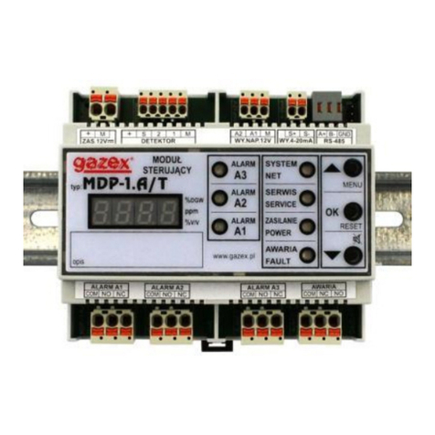
gazex MDP-4 User manual

Warsaw
Measuring
Control
Unit
type/model
edition 6PU63en
MDP-4
MDP-4.A
MDP-4.B
MDP-8
MDP-8.A
MDP-8.B
MDP-16
MDP-16.A
MDP-16.B
MDP-4.Z
MDP-4.ZA
MDP-4.ZB
MDP-8.Z
MDP-8.ZA
MDP-8.ZB
MDP-16.Z
MDP-16.ZA
MDP-16.ZB
series U6
INSTRUCTION
MANUAL
Read carefully this entire manual
BEFORE installation.
For safety reasons during installation
and operation of the device it is
necessary to comply with
recommendations and warnings
marked with this symbol.
The installation can be started after
the content of this manual has been fully
understood.
Keep the manual as reference for the User.
NOTE: This device is equipped with a function blocking in the case
of interference in the internal circuits!
1. General purpose and selection table page 2
2. Description and manner of connecting in the system 4
3. Technical parameters 7
4. Installing the MDP in the system 8
5. Initial configuration MDP 10
6. Start-up MDP in the system 17
6.5 PROBLEM? Helpful information 21
7. Maintenance and operation 22
8. Storage of MDP 23
PRODUCER:
©gazex ’2011. All rights reserved. Reproduction or copying in part or in whole without permission of GAZEX prohibited.
The GAZEX logo, the names of GAZEX, dex, ASBIG - Active Gas Installation Safety System are registered trademarks of the GAZEX company.
You live and work safer with us!!! ©gazex
MDP-4(8,16)… Instruction Manual edition 6PU63en ©gazex’2011 v1101 Page 1 / 24

1. GENERAL PURPOUSE
The MDP-4.(-,A,B,Z,ZA,ZB), MDP-8.(-,A,B,Z,ZA,ZB), MDP-16.(-,A,B,Z,ZA,ZB) U6 series Control
Units are dedicated to use with 4-20mA transmitters/gas detectors type DEX®/P and DG/P series made
by GAZEX. It is possible to connect DEX®/F and DG/F type threshold detectors too.
In the remainder of this Instruction, the term "detector" or "DEX" will refer to DEX/P or DG/P
detectors for all types of gases, the term “MDP” will refer to MDP for all types, except that the description
will apply to a specific type / model.
The MDP can control the work of one to four (MDP-4…), to eight (MDP-8...) or up to sixteen (MDP-
16...) detectors in the measuring or threshold version. A K-8P or K-16P cable hub in version U4 or later
can be used for cooperation of MDP units with detectors. MDP-4 don’t require in cooperation with the
measuring detectors a cable hub, and in cooperation with at least one threshold detector needs a K-8P
hub.
The MDP...-Z... unit can control independently the work of two MAG-3 shut-off valves.
Features and functions performed by MDP:
♦ supplies (9VDC) individual detectors - can work with measuring detectors 4-20mA: DEX/P, DG/P and
DEX/F and other threshold detectors manufactured by GAZEX, as well as with detectors equipped
with relay output;
♦ monitors the status of a wired connection with the detectors (ensures complete detection of
emergencies, clearly defining the type and location of faults);
♦ controls the value of current drawn by the individual detectors and in case of failure of any one of
them automatically disconnects the power without blocking the work of other detectors (independent
hardware and software protections);
♦ assigns - three alarm levels to each measuring detector: two, A1 and A2 - set by the user to any value
in the full range (A1 ≤A2 ≤100% of range), third, A3 constant - determines the range exceeding the
detector; - two alarm levels A1 and A2 to each detector;
♦ allows calculation of the weighted average TWA and average STEL for measuring toxic gas detectors
♦ allows to specify the type of display measuring units: [%] range, [% LEL], [mA] or [ppm];
♦ allows assigning individual detectors to one of two zones to control various external devices,
depending on in which group of detectors alarm occurred (in fact it creates two detection systems);
♦ the MDP unit in version …Z controls operation of two shut-off valves and controls the efficiency of the
wired connection of the unit to the valves (one valve is assigned to one zone);
♦ allows the additional three modes of operation: SILENT MODE - silences the internal piezoceramic
buzzer or temporarily blocks (for 15 minutes) the signalling device at output A2 (12V voltage);
SERVICE MODE - temporarily deactivates outputs of the unit; AUTO RESET - automatically resets
memory status of outputs and inputs on the unit’s display after decay of emergency state,
♦ allows for closing the valves by manual triggering of output control signals (no need for generation of
detectors’ alarm signals);
♦ signals fault states and alarm states through generation of proper messages on graphical LCD
display and turning LED lams on, as well as by means of acoustic signals (in-built buzzer);
♦ allows to select the type of messages displayed on the LCD screen between the measuring window,
that includes the current detector signal values scaled in measuring units, or a treshold window, that
contains messages about alarms and fault of MDP
♦ stores in non-volatile, internal memory the last 1,600 events in 1600 with corresponding start and end
times and with origin of the event;
♦ allows very precise setting of alarms’ delays and constancy of those parameters in time thanks to
microprocessor control;
♦ allows for 12VDC supply of additional equipment;
♦ by alarm inputs (galvanically separated) allows for cooperation with additional devices and units
(cascade);
♦ 12VDC alarm outputs. control additional acoustic and optical signalling devices
♦ relay outputs (galvanically separated from the system) control fans, motors, contactors,
information boards, or connect with building’s/facility’s automatics;
♦ activation of outputs depending on the number of alarms on the inputs: at least 1 or 2 detectors
in alarm;
♦ relay output "FAULT" (galvanically separated) indicates the failure state of MDP, damage to
fuses, damage to line connecting the detector or power failure;
♦ RS232 serial communication channel can work in two modes: Printer mode or
Modbus/RTU - cooperation with control system of an “intelligent building” (after application of
RS232/RS485 converter).
MDP-4(8,16)… Instruction Manual edition 6PU63en ©gazex’2011 v1101 Page 2 / 24

DEX/P
230V~
(12V=)
...
Relay
DEX/F
MDP-4 (8,16)...
Alarm Inputs
MAG-3
SL
DG/P
K-8(16)P
RS232
Cable Hub
GPRS
PC
WG
230V~
(12V=)
A
irTECH
S-3
LD
12V=
RS485
DG/F
Outputs
CONNECTION BLOCK DIAGRAM
MDP SELECTION TABLE
TYPE MDP- 4 4.A 4.B 4.Z 4.ZA 4.ZB 8 8... 16 16...
Max. number of detectors 4 4 4 4 4 4 8 8 16 16
Alarm changeover relay
OUTPUTS 2+2 2+2 2+2 2+2 2+2 2+2 2+2 2+2
FAULT changeover relay
OUTPUTS 1 1 1 1 1 1 1 1
12V voltage alarm OUTPUTS 2+2 2+2 2+2 2+2 2+2 2+2 2+2 2+2
12V voltage insulated alarm
INPUTS 2 2 2 2 2 2 2 2
High-current 12V OUTPUT for
control of shut-off valve - --2 2 2 --
Supply VOLTAGE 230V~ 12V= 230V~ 230V~ 12V= 230V~ 230V~ 230V~
Internal battery-powered
power backup + +
as for
MDP-4…
as for
MDP-4…
Recommended cable hub -K-8P K-16P
Fig. 1.2. Required assembly area
~330
minimum
Cover operation field
281
~120 220
300
Cables installation field
Fitting wholes
150
330
TOP VIEW
MDP-4(8,16)… Instruction Manual edition 6PU63en ©gazex’2011 v1101 Page 3 / 24

2. DESCRIPTION AND MANNER OF CONNECTING IN THE SYSTEM
Fig. 2.1 View of front board (under transparent cover)
www.gazex.com
gazex 2011
ALARM 1
ALARM 2
INTERPRETATION OF DISPLAY MESSAGES:
N
A1
H1
A2
H2
A3
S
Pr
- detector switched off
- normal
- level 1 alarm in progress
- level 1 alarm expired
- level 2 alarm in progress
- level 2 alarm expired
- exceeded the ranges
- signal line failure (break)
- power supply line failure
DETECTORS STATES:
-
A1Z1
A1Z2
A2Z1
A2Z2
VAL1
VAL2
InA1
InH1
InA2
InH2
- level 1 alarm at output in zone 1
- level 1 alarm at output in zone 2
- level 2 alarm at output in zone 1
- level 2 alarm at output in zone 2
- pulses closing the valve at zone 1 output were generated
- pulses closing the valve at zone 2 output were generated
- level 1 alarm at alarm input
- level 1 alarm at alarm input expired
- level 2 alarm at alarm input
- level 2 alarm at alarm input expired
OUTPUTS STATES:
FAILURE STATES:
FDET
ABSENT VALVE1
ABSENT VALVE2
FACC
FVAC
FVDC
- failure at detector’s input
- too low voltage of internal battery
- failure of 230V~ supply
- failure of module supply systems or external supply voltage 12V=
TYPE:
ACCURATE DESCRIPTION OF THE DISPLAY MESSAGES
IN THE USERS MANUAL
LCD Display Control buttons
LED lights MDP version no.
MDP-4(8,16)… Instruction Manual edition 6PU63en ©gazex’2011 v1101 Page 4 / 24

Fig. 2.2 Description of terminal strips and manner of connecting in the system
DEX/F
A
Koncentrator K-8P (K-16P)
DEX/P
1 - 8
1 - 16
.... .....
SL-31
C3
M
B
Pz1
MAG-3
SK
Independent
connection
of 2 valves
~230V
+
-
PS SUPPLY VOLTAGE
ACCUMULATOR
17Ah ENCLOSURE-
PE CLAMP
+
~230V
MDP-4.ZA
MDP-8.ZA
MDP-16.ZA
E
Power connection - 12V DC
Unit no. N+1
(summary)
Unit no. N
wyjścia
nap. 12V
Unit no. N-1
wyjścia
nap. 12V
Cascade connectionMDP
PS-3 for MDP-4(8).ZA
PS-6 for MDP-16.ZA
THE MAIN
POWER
SWITCH
K
light indicating
the presence
of the power
detector
A16
12345678
DETEKTORY ( DETECTORS )
A1 A2 A1 A2
12V
DC S1 S2
A1 A2
S1/S2
M
R
T
++
MM
ZAW1 ZAW2
S1 S2
A2
A1 A2 A1 A2
AWARIA
(FAULT)
STREFA (ZONE) S1 STREFA (ZONE) S2
S1+S2
WYJŚCIA STYKOWE (RELAYS)
GAZEX 2006 MDP-4(8,16)v.U4MD-8(16)v.U4,
WYJ. NAP.
12V, I<0,2A
(OUT)
N L
01 02 03
04 05 06 07 08 09 10 11 12 13 14 15 16 17 18 19 20 21 22 23 24 25 26
27
28
29
RS232
+ S M
30 31 32
+ S M
30 31 32
+ S M
33 34 35
+ S M
36 37 38
+ S M
39 40 41
+ S M
42 43 44
+ S M
45 46 47
+ S M
48 49 50
+ S M
51 52 53
9 10111213141516
DETEKTORY ( DETECTORS )
+ S M
64 65 66
+ S M
67 68 69
+ S M
70 71 72
+ S M
73 74 75
+ S M
76 77 78
+ S M
79 80 81
+ S M
82 83 84
+ S M
85 86 8754 55 56 57 58 59 60 61 62 63
9 10111213141516
DETEKTORY ( DETECTORS )
+ S M + S M + S M + S M + S M + S M + S M + S M
A
DET1
1 2
+ S 2 1 M
DET8
+ S 2 1 M
RS-232
RS-485
DATA+ DATA-
Control
system
TxD RxD M
MDP-4(8,16)… Instruction Manual edition 6PU63en ©gazex’2011 v1101 Page 5 / 24

Table 2.1. Functions performed at the outputs:
CONTACT OUTPUTS
Z1 ZONE Z2 ZONE
FAILURE A1 A2 A1 A2
UNIT
STATUS
Terminal
no.
Pair
NO-COM
(17-16)
Pair
NC-COM
(18-16)
Pair
NO-COM
(05-04)
Pair
NC-COM
(06-04)
Pair
NO-COM
(08-07)
Pair
NC-COM
(09-07)
Pair
NO-COM
(11-10)
Pair
NC-COM
(12-10)
Pair
NO-COM
(14-13)
Pair
NC-COM
(15-13)
NORMAL Opening Shorting Opening Shorting Opening Shorting Opening Shorting Opening Shorting
A1 Z1 Opening Shorting Shorting Opening Opening Shorting Opening Shorting Opening Shorting
A2 Z1 Opening Shorting Shorting *OPENING* Shorting Opening Opening Shorting Opening Shorting
A1 Z2 Opening Shorting Opening Shorting Opening Shorting Shorting Opening Opening Shorting
A2 Z2 Opening Shorting Opening Shorting Opening Shorting Shorting *OPENING* Shorting Opening
version MDP-4(8,16).(B,ZB) - status of outputs according to the actual MDP status
MDP power
FAILURE Shorting Opening
version MDP-4(8,16).(-,A,Z,ZA) - status of outputs as in NORMAL state
DETECTOR
FAILURE Shorting Opening
status of outputs acc. to the current unit status or memory of alarm state from the
damaged detector until manual reset of MD
12V= ALARM OUTPUTS, Iout<200mA
Z1 ZONE Z2 ZONE
UNIT
STATUS
Terminal
no.
A1
(56-57)
A2
(58-59)
VALVE1
(19-20)
A1
(60-61)
A2
(62-63)
VALVE2
(22-21)
NORMAL no voltage no voltage no voltage no voltage no voltage no voltage
A1 Z1 12VDC no voltage
no voltage no voltage no voltage no voltage
A2 Z1 12VDC 12V=
12V impulses no voltage no voltage no voltage
A1 Z2 no voltage no voltage no voltage 12VDC no voltage
no voltage
A2 Z2 no voltage no voltage no voltage 12VDC * 12VDC 12V impulses
MDP power
FAILURE
version MDP-8(16)(B, ZB) - according to the current status of MDP; other versions - no voltage
DETECTOR
FAILURE status of outputs acc. to the current unit status or memory of alarm state from the damaged detector until manual reset
of MDP
* - forced by status of detectors at MDP inputs
Description of MDP statuses:
A
ctivation of outputs from a specific zone occurs when the number of detectors indicating an alarm of one
type is equal or bigger than a minimum number of Lminalarms, specified in the user menu in “Output Off
- logic” tab (1 or 2 detectors can be selected).
NORMAL state – number of alarms of one type at detectors’ inputs does not exceed Lmin (no designation
on LCD screen); only green power light lit on,
A1 Z1 – alarm A1 in zone 1; at least Lmin detectors of Zone 1 indicate exceeding of A1 concentration
threshold (designation “A1Z1” on LCD), but no less than Lmin detectors in that zone indicate
exceeding of A2, ALARM1 light is active,
A1 Z2 – alarm A1 in zone 2; at least Lmin detectors of Zone 2 indicate exceeding of A1 concentration
threshold (designation “A1Z2” on LCD), but no less than Lmin detectors in that zone indicate
exceeding of A2, ALARM1 light is active,
A2 Z1 – alarm A2 in zone 1; at least Lmin detectors of Zone 1 indicate exceeding of A2 concentration
threshold (designation “A2Z1” on LCD), ALARM2 light active, generation of two impulses closing
Zone 1 valve (designation “VAL1” on the LCD screen (if applicable),
A2 Z2 – alarm A2 in zone 2; at least Lmin detectors of Zone 2 indicate exceeding of A2 concentration
threshold (designation “A2Z2” on LCD), ALARM2 light active, generation of two impulses closing
Zone 2 valve (designation “VAL2” on the LCD screen (if applicable),
MDP power supply FAULT - all lights and display disabled (in B, ZB versions green light is flashing and
the FAULT yellow light is lit),
DETECTOR FAULT - the FAULT yellow light is on, “FAULT” word is active on the screen and the “PR” or
“S” symbol for the damaged detector(s)
Statuses for both zones are displayed independently. Other combinations of outputs’ states should be treated as
an emergency.
MDP-4(8,16)… Instruction Manual edition 6PU63en ©gazex’2011 v1101 Page 6 / 24

3. TECHNICAL PARAMETERS
Supply voltage MDP-4(8,16).(-,B,Z,ZB) - 230V~,50Hz (admissible variations +10%,-14% )
MDP-4(8,16).(A,ZA) - 12V= ( admissible: 11.5V - 14.0V)
Power consumption MDP-...(-,B,Z,ZB): max. 65W, MDP-...(A, ZA): max. 55W
Operating temperature
0°C to 40°C constantly permissible,
+5°C to 35°Crecommended optimal; from -5°C to 45°Ctemporarily permissible (<2h/8h, with front
board’s cover closed)
Storage temperature 5°C to 35°C , recommended for the period of > 4 weeks; -10°C to 45°C(short-term)
Number of measuring channels 4for MDP-4…, 8for MDP-8... ; 16 for MDP-16...
Communication with the
detector
measuring detector - three-lead line, 4-20mA
threshold detector - four-lead line, alarm thresholds A1 and A2
Accuracy no more than ± 2% FS
Alarm levels for DEX/P, DG/P
tree: warning - ALARM 1 ( A1 ) – set of 4-20mA (0-100%) or
- TWA ( T1 ) – time-weighted average - 8h/day
alarm - ALARM 2 ( A2 ) – set of 4-20mA (0-100%) or
- STEL ( T2 ) – short term exposure limit - 15 minutes
exceeded range - ALARM 3 ( A3 ) – fixed to the value of 20 mA (100%) (only manual cleared,
cuts off the power detector with a catalytic sensor)
Alarm levels for treshold
detectors DEX/F, DG/F
two: warning - ALARM 1 ( A1 )
alarm / shut-off - ALARM 2 ( A2 )
tree: warning - ALARM 1 ( A1 ) – set of 4-20mA (0-100%)
Failure levels for detector’s
signal
two: opening of signal line - ( S) for I<2mA
shorting of signal line - ( Pr ) for I>25mA
Alarm memory
for each channel and each level - optical (individual message on LCD + cumulative LED light,
cumulative acoustic);
memory of output signals of every level - optical
Unit reset with the button located on the front board (access after lifting up the cover)
Event memory internal, non-erasable, 1,600 events (alarms, emergencies, configurations)
Signal blocking
Output: default 1 min., adjustment: 1÷20 min (pre-heating of sensors)
input: default 10 sec., adjustment: 3 ÷120 sec. (delay of inputs);
output: default 10 sec., adjustment: 3 ÷120 sec. (delay of switching the inputs on)
input: zone 1 and 2: by default 3 sec., adjustment 3 sec.÷15 min
(independent of delay of outputs of zones 1 and 2)
Optical indication of the
measurement results
graphical LCD display (messages for each detector and output)
displays the current values of the signal measurement of each detector scaled in selected
concentration units:% FS,% LEL, ppm or mA
Acoustic signalling
Internal piezoceramic speaker: volume ca. 60dB/1m;
interrupted tone - signalling of finished alarm,
continuous tone - indication of the ongoing alarm or emergency;
(optional: without sound signalling = “SILENT MODE" activated from the menu)
Supplying detectors 9V=, protection against shorting and exceeding the current of 200mA,
switching on detectors’ power - with software via the keyboard software (available from the menu)
Signalling of failure yellow LED light, messages on graphical display
Signalling of switching the
detector on message on the graphical display individually for each detector
Quick triggering of input
signals
with buttons on front board, successive release of each contact and voltage outputs of the unit
(available from user menu)
Switching outputs off
default: automatic - emergency state erased after decay of alarm source with the delay from 3
sec. to 15 min. (Alarm’s memory on LCD),
option: manually - alarm’s status on output is maintained after decay of alarm’s source until the
moment of manual reset (via the keyboard with the “OK” button)
Unit supply control LED light, green, also indicates the pre-heating MDP
Digital output
RS-232 serial port: ASCI printer mode or a Modbus/RTU protocol,
parameters: 9600/19200bps,8,N/P,2/1; selection from the menu; terminal connector;
optional: connecting conduit RS232, RS-232 to RS-485 converter; software used for readout of
events from MDP memory (Windows 98, XP);
Relay outputs
shorting and opening for A1, A2 and FAULT, volt-free;
rating: ≤4A (at resistance load) or ≤2A (at inductive load) or ≤0.6A (with only inductive load -
fluorescent lamps); max. 230V~ or 24V=
Alarm outputs
12V=, not stabilized, for A1 and A2 states independently, load = max. 0.2 A, for connection of
SL-21, SL-31, S-3, LD-2 signalling devices
impulse, high-current for control of shut-off valves, only A2
12V= constant, not stabilized, for supplying MDX unit or other devices, max. load of 0.2 A
Alarm inputs
voltage 12V= (5-16V, max. 20mA) for A1, A2;
quick-break, galvanically separated from other MDP circuits;
for cascade connection of units or other devices
Overload
Protection
primary 230V~ or 12V= power circuit fuse; automatically reset fuses with limitation of shorting
current of NAP.12V outputs; electronic fuses with limitation of current of each detector; additional
system and program protection
Dimensions/weight 300 x 330 x 150 mm, (height, width, depth in assembly position); ca. 3.6 kg
Housing ABS, IP54, 9 gland ducts, 3-point mounting
MDP-4(8,16)… Instruction Manual edition 6PU63en ©gazex’2011 v1101 Page 7 / 24

4. INSTALLING MDP IN THE SYSTEM
Installation of the MDP can proceed after time necessary for compensation of temperatures of the MDP unit and
the surrounding air. Especially in the winter, with temperature below zero centigrade, during transportation or
storage wait 20 minutes before taking out of the foil package to prevent condensation of water vapour on
internal circuits of the device. NOTE: the LCD can work improperly at temperatures <0°C!
4.1 Mount the unit in a designated place, inaccessible to outsiders, outside the EX zone, free from
strong electromagnetic interferences, vibration or shocks.
4.1.1 Unscrew the lid of the terminal chamber- it reveals access to two assembly holes.
4.1.2 Hang the unit on a previously prepared hook (in the middle of an indicated assembly location); mark
locations of two other assembly holes (assembly position acc. to fig. 1.2)
4.1.3 Insert pins; screw the unit in. Assembly of the unit needs to be solid, secure and without any
clearance.
4.2 Note!!! Carry out installation only when the power is off and the main switch of the MDP
unit is switched off!!
4.3 Lead connecting cable(s) “A16” through gland seal ducts from the cable hub (1÷3 cables with a
summary number of conductors > 27 for K-8P or >54 for K-16P, necessary with round section
and external diameter of <13 mm). Length of the “A16” cable depends on the length of “A” cable
connecting DEX detectors with the hub.
TABLE 4.3. Selection of conduits for detectors depending on the model of detector (with a
semiconductor sensor: -nn, infra-red: –(P)nR, catalytic: –Pn)
Conduit (fig. 2.2) Conductor’s
section mm2Permissible length of conductors
0.2 1m < 10m < 20m - -
A16 0.5 1m - - < 50m < 100m
0.5 < 150m < 150m < 100m < 100m < 30m
1.0 < 300m < 300m < 200m < 200m < 60m
A (-nn, -(P)nR)
(for the length A16
as above) 1.5 < 450m < 450m < 300m < 300m < 90m
0.5 < 100m < 75m < 50m < 50m < 15m
1.0 < 200m < 150m < 100m < 100m < 30m
A ( -Pn)
(for the length A16
as above) 1.5 < 300m < 225m < 150m < 150m < 40m
For detectors with electrotechnical sensors, with model designation: -(P)nE/N - all lengths of “A”
cable in Table 4.3 (depending on “A16”) can be assumed as “<450m”.
4.3.1 Preserve the proper sequence of connecting conduits with detectors - improper order will
result in system malfunctioning.
TABLE 4.3.1. Description of connections between MDP and K-8(16)P cable hub (numbers of
terminals).
Detector no. DET1 DET2 DET3 DET4 DET5 DET6 DET7 DET8
Input mark + S M + S M + S M + S M + S M + S M + S M + S M
MDP terminal
no. 30 31 32 33 34 35 36 37 38 39 40 41 42 43 44 45 46 47 48 49 50 51 52 53
K-8(16)P
terminal no. 81 82 83 84 85 86 87 88 89 90 91 92 93 94 95 96 97 98 99
100
101
102
103
104
Detector no. DET9 DET10 DET11 DET12 DET13 DET14 DET15 DET16
Input mark + S M + S M + S M + S M + S M + S M + S M + S M
MDP terminal
no. 64 65 66 67 68 69 70 71 72 73 74 75 76 77 78 79 80 81 82 83 84 85 86 87
K-8(16)P
terminal no.
105
106
107
108
109
110
111
112
113
114
115
116
117
118
119
120
121
122
123
124
125
126
127
128
MDP-4(8,16)… Instruction Manual edition 6PU63en ©gazex’2011 v1101 Page 8 / 24

4.3.2 Inserting a conductor to a self-
locking terminal (straight or slanting)
1. remove the conductor’s insulation
at the length of exactly 9 to 10 mm
(straight)
or 8 to 9 mm (slanting)
2. maximally push (insert) the
exposed end of the conductor to
the round opening of the terminal.
Correctly inserted conduit cannot be pulled
out of the terminal. Releasing and
taking the conduit out is possible after
pressing lever 3 (white or grey,
according to arrow 3).
4.3.3 Inserting a conductor to a
spring cage terminal:
1. remove the conductor’s insulation
at the length of exactly 5 to 6 mm
(exactly!)
2. press the spoon level of the
terminal with a thin screwdriver
3. insert the conduit’s conductor into
the exposed opening in the
terminal
4. release the lever
Correctly inserted conduit cannot be
pulled out of the terminal. Release
of the conduit and possibility of its
removal takesplaceafter
pressing the lever.
1.
9 - 10 mm
2.
3.
8- 9 mm
1.
1.
5 - 6 mm
2.
3.
4.
4.3.4 Ends of the conduits need to be prepared in such manner that after inserted into the
terminal chamber conductors fastened in clamps did not have to be wrapped inside the unit
and the gland’s seal covered the external insulation layer of the cable. It is recommended to
use wire conduits. Cord conduits can be used only with clamping sleeves. Clamping of the
conduit in the gland should be solid enough to keep the conduit inside the MDP during the
attempt of manual pulling it out (and to prevent the conduit from transferring mechanical
forces into terminal’s clamps). That will provide a proper sealing.
4.3.5 The unit is provided with originally deactivated all detectors’ circuits. During installation go
to the “user menu” and activate the required number of detectors (detailed description of
unit configuration can be found in section 5).
4.4 For MDP-Z connect supply conduit “M” of valve to clamps [VALVE1] (19-20) or
[VALVE2] 21-22), neutral polarization. The unit is provided with originally
assembled resistors on clamps [VALVE], which need to be REMOVED before
connection.
4.4.1 TABLE specifying selection of “M” conduit (fig. 3) connecting the valve and the MDP:
The biggest length of “M” conduit [m]
Type of shut-off valves cross-section of conductor of a conduit
< 1.5mm21.5 mm22.5 mm25(2x2.5)*mm2
MAG-3 14 22 45
2 x MAG-3** 610 20
SK-3 610 20
MAG-1 610 20
MAG-2 22 36 70
other shut-off valves
with COD-1/10A coil 610 20
other shut-off valves
with COD-1/3A coil
22 36 70
ZB 30 50 100
NOT
RECOMMENDED
* - ends of conduit (YDY4x2,5) inside the MDP and Pz1 should be provided with necessary
adapters for 2.5 mm2(it is recommended to use WAGO blocks with self-springing clamps)
** - if a single conduit is used (when laying two conduits connected in the MDP - lengths as for
the “MAG-3” column)
MDP-4(8,16)… Instruction Manual edition 6PU63en ©gazex’2011 v1101 Page 9 / 24

4.4.2 It is recommended to connect the valve with a homogenous conduit. Connection on the “M”
conduit should be made as solid as possible, providing good contact on connections with
the use of tight (IP44) clamp block - PZ1 on Fig. 2.2.
4.5 Connect external auxiliary device, e.g. automatics control, external buzzer S-3, warning lamp LD-
2 (YTKSY 2 x 0.5 conduits), etc. In case of positioning optical and acoustic signalling devices in
the same location, it is recommended to use an integrated acoustic-optical signalling device of
SL-21 of SL-31 type. Having separated functions of buzzer and lamp, it can be connected to
MDP with a three-conductor conduit (YTKSY 2x2x0.5 recommended). Labelling of outputs and
their features were described in Table 2.1.
4.5.1 When it is necessary to connect a larger number of conduits (after using all factory gland
ducts), additional ducts (with diameter adjusted to conduits used) need to be installed on
the removable cover of the terminal chamber. Only correct ducts (IP54 or better) should be
used to maintain the proper level of unit’s tightness. Walls and bottom of the unit must not
be perforated! Conduits cannot be inserted directly to the unit by the drilled holes (without
gland ducts) or through the seal of the terminal clamp.
4.6 For MDP-4(8,16) connect ~230 power supply cable “B”. The unit has an internal, unipolar power
switch. Maintain the proper sequence of 230V~ connection’s conduits: neutral to “N” (01), phase
to terminal “L” (02), PE ground cable to terminal (03). Certainty of power supply and no
interferences is a basic requirement for system efficiency and therefore conduit “B” should be
connected through the isolated fuse in the switchboard. Strong overvoltage in the ~230V supply
circuit can be the cause of damage of internal main supply fuse or cause interferences in
operation of the MDP unit.
For the MDP version: connect the 12V= supply cable “E” from the PS-3 power supply unit
(MDP-4(8)..A) or PS-6 (MDP-16…A) with the battery connected, maintain proper polarization (the
unit is protected by inverted polarization), (“+” to terminal “02”, “-” to terminal 01).
TIME LOCK
ACTIVATION: 2011-03-15 12:00:00
To enter the password
- press the “OK” key
time left: 05 sec
Section of conductors in “E”
conduit Length of conduit "E"
1.5 mm2 (YDY 2x1.5) < 4m
2.5 mm2 (YDY 2x1.5) < 6m
5* mm2 (YDY 4x2,5) < 12m
* - see notes under Table 4.4.1
5. INITIAL CONFIGURATION MDP
NOTE: all described procedures and messages of the LCD screen concern the standard version of the
unit. Possible descriptions of non-standard versions, modifications and revisions may be found in
attached appendix to the instruction manual (if any).
NOTE: Press the keys gently not to damage mounting plates and internal circuits of the MDP.
5.1 The next stage of System activation is to configure the unit according to individual needs of
the Customer. It is conducted by means of the keyboard located in the front panel of the unit accessible
after opening of the transparent cover of the housing.
5.2 Switch on the power supply with the unit’s main switch. After power is turned on a test of signalling lights is
performed. The lights of Alarm2, Alarm1, Power supply, Failure are turned on and off in sequence. Then the
logo of Gazex company will appear on the LCD. The logo is displayed for 5 sec.
At this time initialization of unit’s settings takes place.
5.3 The next stage (optional, for selected models) is the stage of temporary deactivation of the
unit’s blocking. If the blocking is active, the dialog box presented below will be visible on the
screen. The date shown in the box specifies the date, after which the unit will be blocked. By
this time the unit is fully functional.
After conditions forcing the blocking are fulfilled,
contact service employees of GAZEX (by phone
under +48 22 6442511 or via the contact form
available at www.gazex.pl or by mail:
code for deactivation of temporary blocking of the
unit.
MDP-4(8,16)… Instruction Manual edition 6PU63en ©gazex’2011 v1101 Page 10 / 24

5.4 After the stage of activation or omission thereof, the unit switches to configuration mode:
CONTROL UNIT SETTINGS
Settings - press the “OK” key
time left: 30 Sec
For 5 seconds the LCD screen will display information concerning type and version of the unit, serial number
and dates of changes made to the software. That information can be required during contact with service
employees of GAZEX.
The next dialog box allows for changes in the unit’s settings.
To do that press the “OK” button within 30
seconds. Then enter user password:
“LLLLL” (press the “L” button five times).
Note!!! The above password is a standard
password assigned to all MDP units. To
protect against unauthorized
access of third parties to the
settings, change the password
(that action has been described further in section 5.4.3). The changed password should be
remembered and kept in a safe place. Lost password will make it impossible to change the unit’s
configuration. The password can only be unlocked by GAZEX service (extra paid).
After a correct password had been entered, the user menu will be displayed on the LCD
with available functions:
5.4.1 Detectors and alarm inputs perform the below features.
01’2011
Control Unit MDP-8 U6.3
Serial number: 00457328
Date of changes made to the software
Type and version of the unit
Unit serial number
Feature selection with “U” and “D” keys,
Confirmation with “OK” ke
y
Select:
Detectors and alarm inputs
Outputs
Event history
Service Info
User password
System settings
Exit
Feature selection with “U” and “D” keys,
Confirmation with “OK” ke
y
Select:
Detectors - on / off
Detectors - zones
Detectors - parameters
Alarm inputs - zones
Inputs delay: 10 sec.
Detectors – heating time: 60 sec.
Exit
1) Detectors - power supply on/off.
DETECTOR: 1 2 3 4 5 6 7 8
Detector status: Y Y Y Y Y Y Y Y
DETECTOR: 9 10 11 12 13 14 15 16
Detector status: Y Y N N N N N N
Change – press , Exit – press <OK>
Denotes:
Detector 8 - switched on
The flashing “Y” or “N” symbol denotes the selected detector. Select the correct detector with “L”
and “R” keys and then with “U” and “D” keys change its status into one of the following: “Y” -
detector is switched on, “N” - detector is switched off. To confirm the settings, press the “OK”
button.
Presence of supply of a specific detector is confirmed by a green light next to connection terminals
of the detector in the K-8(16) cable hub.
MDP-4(8,16)… Instruction Manual edition 6PU63en ©gazex’2011 v1101 Page 11 / 24

2) Detectors - zones.
Select:
Zone 1
Zone 2
Zone 1+2
Exit
Current Settings: Zone 1+2
Change -, Confirm - <OK>
The flashing cursor denotes the selected detector. Select the correct detector with “L” and “R” keys
and then with “U” and “D” keys change assignment of a detector to a zone: “1” - detector is
assigned to zone 1; “2” - detector is assigned to zone 2; “1+2” - detector is assigned
simultaneously to both zones. To confirm the settings, press the “OK” button.
3) Detectors - parameters.
The cursor denotes the selected detector. Select the correct detector with “L” and “R” keys and
then with “U” and “D” keys select a required detector’s parameter, change the parameters with “L”
and “R” keys. To confirm the settings, press the “OK” button.
The parameter "alarm type" allows two choices: "tresholds levels" - the temporary value of alarm
thresholds A1 and A2 adjustable over the full measuring range; "time-weighted average - the
threshold of T1 corresponds to the TWA (Time-Weighted Average - 8h/day), the threshold T2
corresponds to the STEL (Short Term Exposure Limit – 15 minut)
Note!!! For connecting the threshold detector DEX/F or DG/F to MDP select “DEX - A1,A2
tresholds”, for WG and AirTECH detectors with NC contact outputs select “BIN -thresholds A1, A2”.
Cooperation with threshold detectors requires the use of cable hub K-8P or K-16P, and setting the
"Cable Hub" to "connected" (see 5.4.6, 3C)
4) Alarm inputs - zones.
Select correct option with “U” and “D”
keys and confirm with “OK” key.
Additionally a selected option is
currently displayed on the LCD screen.
To exit the settings, select the “Exit”
option with “U” and “D” keys and then
press “OK”.
5) Inputs delay (default = 10 sec.) is a time, for which alarm status should be maintained at the
detector’s input, so it could be registered by MDP and signalled with proper message on the LCD
screen. That delay can be set within the range of: 1 ÷120 seconds with “L” and “R” keys.
6) Detectors heating time (default = 60 sec.) is a time after each start of MD, during which stabilization
of the detectors’ operation point necessary for their correct operation occurs. The heating time can be
adjusted within the range of: 1 ÷15 minutes with “L” and “R” keys.
5.4.2 Output settings perform the following functions.
Detector no.: 03
- alarm A1 : TWA
- alarm A2 : STEL
- alarm type : time average values
- calibration gas. : carbon monoxide
- measur. range: 500 ppm
Change - press , Exit - press <OK>
Denotes:
measuring detector no. 3,
alarm T1 = TWA,
alarm T2 = STEL,
meauring range 0-500ppm
Feature selection with “U” and “D” keys,
Confirmation with “OK” ke
y
Select:
Outputs Off – auto / manual
Outputs On – delay : 10 sec.
Outputs Off – zone1 delay : 3 sec.
Outputs Off – zone2 delay : 3 sec.
Outputs On – zone1 logic : 1 alarm
Outputs On – zone2 logic : 2 alarms
Exit
DETECTOR: 1 2 3 4 5 6 7 8
Zone: 1 1 1 1+2 1+2 1 2 1+2
DETECTOR: 9 10 11 12 13 14 1516
Zone: 1
1+2 2 2 1+2 1 2 2
Change – press , Exit – press <OK>
Denotes:
Detector 8 - assigned to zone 1
and zone 2
MDP-4(8,16)… Instruction Manual edition 6PU63en ©gazex’2011 v1101 Page 12 / 24

1) Outputs Off – auto / manual.
Select:
Ouptut Off – zone1, alarm1 : manual/auto
Ouptut Off – zone1, alarm2 : manual/auto
Ouptut Off – zone2, alarm1 : manual/auto
Ouptut Off – zone2, alarm2 : manual/auto
Exit
Change - press .
Select correct output with “U” and “D” keys and then with “L” and “R” keys change the manner of
switching the output off. Manual shutdown means that the output will be switched off ONLY after
external intervention of the user (unit reset with “OK” button). By this time, emergency state will be
maintained ay that output, even after the event that caused the alarm had ended.
Automatic shutdown means that the output will be switched off independently by the MDP after the
alarm that caused the output to switch on had ended. Information about the alarm condition is indicated
by the pulsating sound and relevant messages on the LCD screen until the user resets the MDP.
2) Outputs On – delay (delay of switching the outputs off) is a time (10 sec. by default) from the
moment the MDP registers an alarm condition at detector’s input to the moment, when the MDP
switches appropriate outputs on depending on location of the alarm. That delay can be set within the
range of: 1 ÷120 seconds
3) Outputs Off – zone1 delay (delay of switching outputs of zone 1 off) is a time (3 sec. by default)
from the moment of alarm decay to the moment outputs of zone 1 are switched off. That delay can be
set within the range of: 1 sec. ÷15 minutes (only when automatic shutdown of zone 1 inputs is
selected).
4) Outputs Off – zone2 delay (delay of switching outputs of zone 2 off) is a time (3 sec. by default)
from the moment of alarm decay to the moment outputs of zone 2 are switched off. That delay can be
set within the range of: 1 sec. ÷15 minutes (only when automatic shutdown of zone 2 inputs is
selected).
Alarm Alarm signalling switching of outputs “AutoReset” mode
Alarm decay
unitreset
input status
signalling
outputs status
storing alarms on outputs in memory
(switched off manually)
switching outputs off with delay
(switched off automatically - delay of 3 min)
switching outputs off after alarm decay
(switched off automatically - delay of 1 sec.)
Delay of
switching outputs on
Delay of
inputs
Delay of
switching outputs off
time
5) Outputs Off – zone1 logic defines the minimum quantity of a given type of alarms (A1, A2) on
outputs of detectors activating outputs of zone 1. Two options available: at least 1 or two alarm states.
6) Outputs Off – zone1 logic defines the minimum quantity of a given type of alarms (A1, A2) on
outputs of detectors activating outputs of zone 2. Two options available: at least 1 or two alarm states.
5.4.3 Events history performs the following functions.
MDP-4(8,16)… Instruction Manual edition 6PU63en ©gazex’2011 v1101 Page 13 / 24
Feature selection with “U” and “D” keys,
Confirmation with “OK” ke
y
Select:
Events - viewing on LCD
Events – data transmission
Exit

1) Events – viewing on LCD allows for review of the history of past alarm, emergency and
configuration events. A screen with a sample description of one event has been presented
below.
Event number : 0123 / 1600
Detector 1 – Alarm A1
Start time : 2010-12-14 12:05:11
End time : 2010-12-14 12:30:45
Change - press , Exit - <OK>
Description of messages:
a) Event number – identification number of an event in unit’s memory. Successive numbers
from 1 to 1,600 are assigned to successive events. In the case of exceeding the capacity of
the buffer (1600 events), the oldest events are erased, i.e. event 1601 is registered as
number 1, etc.
b) Event description - specifies the type of the occurred alarm or failure, e.g.:
Detector no. - Alarm A1 (or TWA) Detector no. - Alarm A2 (or STEL)
Detector no. - Alarm A3 Detector no - short line '+' or 'S',
Detector no - open power line '+' Detector no - short signal line 'S'
Detector no. - open signal line 'S' Detector no. - power off
Alarm input - Alarm A1 Alarm input - Alarm A2
Zone 1 Valve - absent valve Zone 2 Valve - absent valve
Zone 1 Valve - impulses were generated Zone 2 Valve - impulses were generated
External power supply fault U<190VAC External power supply fault U>250VAC
External power supply fault U<10,5VDC External power supply fault U>15VDC
Internal power supply fault Uint=12VDC Internal power supply fault Udex1=9VDC
Internal power supply fault Udex2=9VDC Control Unit - reset
Control Unit - power on Control Unit - power off
Internal accumulator fault, no charging Internal accumulator fault - U<14,4VDC
Control Unit - settings changing Service Mode - enabled
Silent Mode - enabled Auto Reset Mode - enabled
System Time - changed MODBUS RTU Master - enabled
RWS - no communication MODBUS RTU Slave - enabled
c) Start time - date and time of the event,
d) End time - date and time of the event.
No date and time of the end of event means that the event lasted until the reset of the unit
or until its switching off.
2) Data transmission allows readout of the history of occurred alarm events by the RS232
serial port. This option requires installation of special software on a PC computer
(Windows 98, XP). The program enables filtration of events of individual detectors and
configuration events, as well as saving history to a text file.
5.4.4 Service Info.
Select:
Signal currents
Power voltages
Outputs test
Zero Settings
Exit
The first two options display parameters of internal circuits of the unit, helpful in solving
problems connected with system installation or in diagnosing the type and cause of unit’s
failure.
Output test - allows checking if all outputs are correctly switched on without the necessity to
generate alarms on unit’s inputs.
Denotes:
Active relay output: zone 1 - alarm 1
Relay output: zone 1, alarm 1
MDP-4(8,16)… Instruction Manual edition 6PU63en ©gazex’2011 v1101 Page 14 / 24

Outputs are switched sequentially at time = 1 sec. Currently switched on input is displayed on
the LCD screen. After all the outputs are tested, MDP automatically switches to the service
menu. The outputs are switched on in the following order:
1. Relay output – zone 1, alarm 1, 6. Valve output – zone 1
2. Relay output – zone 1, alarm 2, 7. Valve output – zone 2
3. Relay output – zone 2, alarm 1, 8. Alarm output – zone 1, alarm 1,
4. Relay output – zone 2, alarm 2, 9. Alarm output – zone 1, alarm 2,
5. Relay output – fault, 10. Alarm output – zone 2, alarm 1,
11. Alarm output – zone 2, alarm 2;
5.4.5 User password - allows changing user password.
Change user password
Enter old password: *******
Enter new password: ****
Repeat new password: ****
Password should contain 2-8 characters
In order to change the password: - enter old password,
- enter new password
- repeat new password
After the new password has been correctly entered, a message “The password has been
changed” will be displayed. The password is a combination of “U”, “D”, “L” and “R” keys and
can contain from two to eight characters. When the password is being entered, it is masked
with characters shown on the screen above.
The new password should be saved and secured. This password will be required at
each entrance to the unit settings. Losing the password will prevent subsequent
modification of the unit by the user! The password can only be unlocked by GAZEX
service employees (extra paid service).
5.4.6 System settings are protected with admin password and allow changing additional settings
only by a skilled used or system installer.
To make changes as an administrator, select this option and press “OK”. Then enter admin
password: “PPPPP” (press the “P” button five times).
Note!!! The above password is a standard password assigned to each unit. To protect
against unauthorized access of third parties to additional unit settings, change the
password.
Admin password should differ from user password. Only then access to additional unit
features will be protected. The changed password should be remembered and kept in a
safe place. Lost password will make it impossible to change the unit’s additional
configuration. The password can only be unlocked by GAZEX service (extra paid).
After a correct password had been entered, the administrator menu will be displayed on the
LCD with available functions:
Select:
Time Settings
RS232 Port Settings
Operating Parameters
Factory Settings
Special Functions
Administrator Password
Exit
1) Time Settings - allows changing current date and time settings:
Current time settings:
2002-12-30 17:55:40
Change - press , Exit - press <OK>
MDP-4(8,16)… Instruction Manual edition 6PU63en ©gazex’2011 v1101 Page 15 / 24

Select item to be changed (year, month, day, hour, minute, second) with “L” and “R” keys.
The selected value will be highlighted with a flashing cursor. Then set the required value with
“U” and “D” keys. If date and time are set correctly, press the “OK” key.
2) RS232 Port Settings - allow changing transmission parameters
Change RS232 port settings:
Operation mode - Modbus RTU Slave
Slave address - 1
Speed - 9,600 bps
Data bits - 8
Parity - Even
Stop bits - 1
Exit
a) Operation mode
- Printer - text messages sent to a port in the following format:
e.g. 2006-09-02 12:23:45 - Detector 01 - Alarm A1
2006-09-05 18:48:23 – Zone 1 – Absent Valve1;
- Modbus RTU Master - the protocol controlling the hub of RWS08(16) contact outputs
or other;
- Modbus RTU Slave - the protocol for communication of the unit with external control
systems (the detailed description of readout and saving of the unit’s register has
been appended to the instruction as: “MDP - Modbus/RTU protocol” - available
upon request);
b) Slave address - unit’s address (slave device) - change from 1÷247;
c) Speed - 9,600 bps or 19,200 bps;
d) Data bits - 8 data bits;
e) Parity - even or none;
f) Stop bits - 1 stop bit with parity control; 2 bit stops with no parity control;
3) Operation parameters - allows changing unit’s functionality.
Change:
SERVICE MODE - enabled / disabled
AUTO RESET - enabled / disabled
CABLE HUB - none / connected
Exit
Change – press
a) SERVICE MODE - allows blocking unit’s outputs for the time of 120 minutes.
Recommended during conduct of maintenance of gas detection systems. In this mode
measuring activities of the unit are maintained, i.e. the unit controls the status of
connected detectors, status of alarm inputs, displays information on alarms and failures
on the LCD screen, but does not activate outputs. The mode can be turned off at any
moment before the lapse of the full period.
b) AUTO RESET - the mode automatically reset the unit’s memory of alarm statuses after
alarm decay; intervention of system user is not required. There are no information on
alarm, which has ended on the LCD screen. Acoustic signals are also switched off.
Information about occurred alarms are saved to the unit’s internal memory. The mode
can be activated for an indefinite time. Especially recommended in ventilation control
systems.
c) CABLE HUB – in "none " (the standard for the MDP-4 ...) allows you to connect the
measuring detectors directly to MDP - without cable hub K-8(16)P; mode "connected"
means the work with an attached hub K-8(16)P (standard mode for the MDP-8 (16 )...).
MDP-4(8,16)… Instruction Manual edition 6PU63en ©gazex’2011 v1101 Page 16 / 24

4) Factory settings - this option restores default unit settings, i.e.:
a. Values of the signal detectors (4-20mA) scaled to 0-100% of range,
b. The alarm thresholds set appropriately A1=10% range, A2=30% range,
c. detectors off, assigned to the two zones "1+2",
d. alarm inputs assigned to the two zones "1 +2";
e. outputs set in auto mode;
f. The delay times set to default values;
g. unit’s operation mode - normal;
5) Special Functions – this option is password-protected, intended for special purposes.
Description of necessary functions is located in annexes appended to this instruction;
6) Administrator password - allows changing admin password.
Change administrator password
Enter old password: *****
Enter new password: *******
Repeat new password: *******
Password should contain 2
-
8 characters
In order to change the password: - enter old password,
- enter new password,
- repeat new password
After the new password has been correctly entered, a message “The password has been
changed” will be displayed. The password is a combination of “U”, “D”, “L” and “R” keys and
can contain from two to eight characters. When the password is being entered, it is masked
with characters shown on the screen above.
The new password should be saved and secured. This password will be required at
each entrance to the administrator’s settings. Losing the password will prevent
subsequent modification of the unit’s system settings! The password can only be
unlocked by GAZEX service (extra paid).
6. START-UP MDP IN THE SYSTEM
6.1 After configuration is over (or configuration stage is omitted by the user), the MDP unit switches to
the detectors’ burn-in mode and signals that by means of a green power supply diode and a
message on the LCD screen.
PRE-HEATING
System starting,
Time left: 1 min 00 sec.
During pre-heating, duration of which is defined in the installer’s menu, operation points of individual
detectors need to be stabilized to operate properly. During this stage all alarm states and
emergency states are blocked.
6.2 After pre-heating the MDP switches to normal operation. The LCD screen in real time signals
statuses of inputs of detectors and alarm inputs, statuses of outputs and critical parameters of MDP
unit’s operation.
“Threshold screen” - displays information on current alarm states and emergency states of
input/outputs of the unit and information on set operation modes.
MDP-4(8,16)… Instruction Manual edition 6PU63en ©gazex’2011 v1101 Page 17 / 24
failure operation
states of detectors states of outputs states modes
"Measuring screen” - displays the measured values of the output signals of the detectors. The
current values of 4-20mA output scaled to ranges and units specified by the user in the menu
timer
6.2.1 Signalled states of detectors’ outputs:
N – normal, –– detector switched on,
A1 – level 1 alarm in progress, A2 – level 2 alarm in progress,
T1 – TWA alarm in progress T2 – STEL alarm in progress;
A3 – exceeded the range,
H1 – level 1 alarm expired, H2 – level 2 alarm expired,
S– failure of signal line (break),
Pr – power supply failure (no or too high detector’s supply current), shorting of signal line.
C – recommendation of detector’s calibration (detector operates, is in normal condition, by
the recommended calibration deadline has elapsed.
6.2.2 Measuring ranges and units of detectors, depending on the measured medium:
Measuring range
(scaled to 4-20 [mA])
The accuracy
of the threshold
alarm
adjustment
Medium
0 – 100 [% meas.range] 1 undefined medium, the default type
0,0 – 25,0 [mA] (no scale) 0,5
undefined medium, DEX - the threshold
detector, A1 and A2 alarm thresholds
0 – 100 [%LEL] EX 1 explosive gas, DEX-nK, catalytic sensor
0 – 500 [ppm] CO 10 carbon monoxide
0 – 100 [ppm] NH3 1 ammonia
0 – 100 [ppm] H2S 1 hydrogen sulphide
0,0 – 25,0 [v/v] O2 (UP) 0,5 oxygen
0,0 – 25,0 [v/v] O2 (DOWN) 0,5 oxygen
0,0 – 20,0 [ppm] ETO 0,5 ethylene oxide
0,0 – 100,0 [ppm] NO 1 nitric oxide
0,0 – 20,0 [ppm] NO2 0,5 nitric dioxide
0 – 1000 [ppm] H2 10 hydrogen
0,0 – 20,0 [ppm] SO2 0,5 sulphide dioxide
0,0 – 10,0 [ppm] CL2 0,5 chlorine
0,0 – 25,0 [mA] (no scale) 0,5
undefined medium, BIN - the threshold
detector, A1 and A2 alarm thresholds
0,0 – 25,0 [v/v] O2 (DOWN,UP) 0,5 oxygen
0 – 2,00 [v/v] CO2 10 carbon monoxide
0 – 100 [%LEL] IR 1 explosive gas, DEX-nR, infra-red sensor
MDP-4(8,16)… Instruction Manual edition 6PU63en ©gazex’2011 v1101 Page 18 / 24
6.2.3 Signalled statuses of outputs and critical unit parameters:
A1Z1 – level 1 alarm at output in zone 1,
A1Z2 – level 1 alarm at output in zone 2,
A2Z1 – level 2 alarm at output in zone 1,
A2Z2 – level 2 alarm at output in zone 2,
VAL1 - pulses closing the valve at zone 1 output were generated,
VAL2 - pulses closing the valve at zone 2 output were generated,
InA1 – level 1 alarm at alarm input,
InA2 – level 2 alarm at alarm input,
FDET – failure at detector’s input,
FACC – voltage of internal battery too low,
FVDC – failure of unit supply systems or external supply voltage 12V=
FVAC – failure of 230V~ supply,
ABSENT VALVE1 - no valve at output of zone 1;
ABSENT VALVE2 - no valve at output of zone 2;
6.2.4 Signalled operation modes:
SILENT MODE - the quiet operation mode causes permanent switching off of the buzzer, to switch the
buzzer on: hold the “L” key for 5 seconds, to turn it off: again hold the “L” key for 5 seconds. The
setting is saved in the non-volatile memory of MDP and is active after power decay or resetting the
unit.
The temporary mode of “quiet operation” can concern external signalling by switching voltage
outputs of A2 threshold in both S1 and S2 zones for 15 minutes; to switch them on again:
simultaneously hold “L” and “OK” keys for > 5 seconds. In that mode the unit signals emergency
states and alarm states only with optical signals (diodes and the display). Switching the temporary
blocking on is signalled by counting down of the time left for its end. The temporary blocking of A2
voltage outputs is automatically switched off after 15 minutes or earlier, in case when a new A2
alarm appears on detectors’ inputs or after the user holds “L” and “OK” keys for > 5 seconds.
AUTO RESET - described in section 5 in administrator menu.
SERVICE MODE - described in section 5 in administrator menu.
MODBUS MASTER - described in section 5 in administrator menu.
MODBUS SLAVE - described in section 5 in administrator menu.
No sound or optical signals should be generated after correct installation, while switched on detectors should
ndic ed with “N” sign on the LCD screen.be i at
Control of MDP unit’s operation is conducted by means of the keyboard located in the front panel.
During normal operation additional functions are permanently assigned to the keyboard’s buttons. Pressing
and holding the button will respectively cause:
<OK> key (3 sec.) - unit reset;
<L> key (5 sec.) - switching the “silent mode” on/off;
<L> and <OK> keys - switching temporary blocking of 12V alarm outputs A2 on/off.
simultaneously <L> and <R> keys (5 sec.)- entering user menu;
<U> and <D> keys - adjustment of illumination of the LCD screen.
If other designations are visible on the LCD screen, yellow or red lamp is glowing and a sound signal is
audible, that means incorrect installation of the detectors. Then check the connections of the detectors
indicated on the LCD screen with a character other than "N" and "-" and remove the fault.
With the shut-off valve connected, the yellow light [FAULT] should be turned off. Lighting up these lights
accompanied with acoustic signal of piezoceramic buzzer and lighting of “ABSENT VALVE1" or “ABSENT
VALVE2” means that a valve/valves is/are not connected.
NOTE: In the case of MDP assuming temporary or constant operation with disconnected valves leave the
standard characteristic resistors in “VALVE” terminals. DO NOT short the terminals [VALVE] by means of
jumper pins!!! This can damage the internal battery or circuits of the unit during the generation of A2 status. It
is forbidden to operate MDP with a connected valve and characteristic resistor left in place!!!
All circuits of inputs have independent mechanisms supervising supply current of detectors. In case of
shorting of detector’s supply conduits, overload of supply line or improper polarization of “A” or “A16” conduit
automatic cut-off of power from a given occurs (status signalled on LCD screen with “Pr” sign, next to a
specific detector number and a constant sound signal). After removal of shorting or overload, MDP restarts
supply of a given line only after power supply of the unit is switched off and switched on again.
MDP-4(8,16)… Instruction Manual edition 6PU63en ©gazex’2011 v1101 Page 19 / 24
Overload or shorting of any voltage outputs “12V ALARM OUTPUTS”during A1 or A2 status will cause
automatic switching off of automatically reset fuse. After removal of overload or shorting the internal fuse
automatically restarts the normal work after not longer that several seconds.
NOTE!!! To disable the unit in MDP-…B version equipped with internal battery support,
disconnect the external power supply with main switch, then press "OK" button
located on the front panel and hold it down until you disable the MDP unit (for about
10 seconds).
6.3 The final stage of the control system’s operation is to check the MDP unit and generate all
alarm states for all connected detectors and to control the efficiency of external devices.
REQUIRED ASSUMPTIONS OF SYSTEM INSPECTION:
- The MDP unit is in normal state (after elapse of the time necessary for burn-in of sensors), the [POWER
SUPPLY] light is on, detectors indicated with “N” sign are on, the value of concentrations displayed on
LCD screen comply with the “zero level” specified in the instruction manuals of individual detectors.
- The unit was stored for not longer than 2 months or was connected to power supply for at least 24 hours
(version B).
- DEX/DG detectors do not generate alarm signals (output current is consistent with the "zero level"
specified in the detector manual);
- In order to obtain a measurement accuracy of the system specified in the manual, should be taken during
inspection of detectors to meet the additional conditions specified in the individual manual for each
detector DEX/P.
6.3.1 Generate alarms of each detector by means o test gas with a known concentration value according to
the instruction manual of the detector. After a time consistent with input delay the indication next to the
tested detector should change into A1, A2 or A3 on the LCD screen, which is a sufficient confirmation
of correct cooperation of detector set with unit.
If the alarm signal A1 and A2 from the DEX detector will continue for at least the time corresponding to
output delay, alarm signal on correct contact outputs will be generated in the zone, to which the
specific detector had been assigned (message on LCD screen A1Z1 and A1Z2, green ALARM1 and
ALARM2 lights will be turned off and a constant sound signal will be activated.
In addition to measuring detectors switch on the LCD measuring screen and see if it appears with the
appropriate detector measured gas concentration is compatible with the given test gas concentration (in
the comparison should take into account the measurement accuracy of the unit, detector and test
mixture).
6.3.2 For MDP-Z - Simultaneously with generation of the alarm state at the control output A2 of the
corresponding zone, two electromagnetic pulses on VALVE terminals (message VAL1 or VAL2 on LCD
screen) should be generated. Generation of the next A2 state must be preceded by a break for
regeneration of internal batteries. The length of that break depends on the initial charging of the battery,
the type of shut-off valves, the number of A2 states generated directly before the next attempt and on
ambient temperature. It needs to be assumed that the break should not be shorter than 5 minutes (10
minutes for two valves) and it should be DOUBLED after each successive attempt (independently of the
fact whether A2 was generated from detectors or with the TEST procedure). After a series of ca. 5
attempts wait for one hour or longer.
6.3.3 After removal of the test gas reduction of gas concentration in the detector takes place, which causes a
change of condition of detector on the LCD screen from H2 and/or H1, depending on completed alarm
state and transition of red lights from constant lighting (if they were lit up) to flashing: first ALARM2,
then ALARM1. The control outputs are back to normal (alarm messages disappear from the LCD
screen), while the sound signal is changed to intermittent. Information about alarms remains on the
display until willingly cleared by a user.
6.3.4 Check the operation of other detectors in a similar manner. When the status of all alarms is marked on
the LCD screen with "H2" - reset the unit by pressing and holding the "OK" button located on the front
panel for 3 seconds. Red lights of “ALARM1” and “ALARM2”should go off and the unit should switch
to normal. Open the valve/shut-off valves!!!
6.3.5 The control procedure 6.3.1 should be complemented with output test conducted with software from the
user menu described in section 5.4.4.
Results of control or start-up should be registered in the attached Periodical Control Protocol.
After a positive test result the GX Active Gas Installation Safety System or the Double-
threshold Gas Detection System can be considered activated and functional.
6.4 Screw the cover of the unit’s terminal chamber:
- tight gland ducts (strong enough to prevent them from transmitting mechanical loads during the attempt
of pull the cable out);
- seal not used gland ducts (e.g. by tightening short sections of the conduit on them);
- tightly close the transparent unit cover. Secure opening of the cover by turning the blocking pin with a flat
screwdriver into horizontal position.
- it is recommended to seal the unit’s cover (to restrict outsiders’ access to MDP unit);
MDP-4(8,16)… Instruction Manual edition 6PU63en ©gazex’2011 v1101 Page 20 / 24
This manual suits for next models
17
Table of contents
Other gazex Control Unit manuals
Popular Control Unit manuals by other brands

Emerson
Emerson PENBERTHY N7 Series Installation, operation and maintenance instructions

Chamberlain
Chamberlain GCU user manual

Compaq
Compaq StorageWorks user guide

Signature Hardware
Signature Hardware Pinecrest 948551 manual

SICK
SICK MSM Series Mounting instructions

Allen-Bradley
Allen-Bradley FLEX Ex 1797-OE8 installation instructions