ViOptix T.Ox OXY-2-USM-1 User manual
Tissue Oximeter
Operator’s Manual
ViOptix, Incorporated
39655 Eureka Drive
Newark, CA 94560
Phone: 510-226-5860 Fax: 510-226-5864 Website: www.vioptix.com

Operator’s Manual Page 2 of 89
OXY-2-USM-1, REV K
About This Manual
Trademarks
T.Ox™ Tissue Oximeter is a registered trademark of ViOptix, Inc.
References
References to “ViOptix” in this manual shall imply ViOptix, Inc.
The information in this manual has been carefully checked and is believed to be accurate. In the interest of continued product
development, ViOptix reserves the right to make changes and improvements to this manual and the products it describes at any time,
without notice or obligation.
Caution: Federal law (US) restricts this device to sale by or on the order of a physician.
Caution: Use of controls or adjustments or performance of procedures other than those specified herein may result in
hazardous radiation exposure
VISIBLE AND INVISIBLE
LASER RADIATION
AVOID DIRECT EYE EXPOSURE
CLASS 3R LASER PRODUCT
690 nm and 830 nm, 3 mW max.
IEC60825-1:1993+A1+A2

Operator’s Manual Page 3 of 89
OXY-2-USM-1, REV K
Copyright 2003-2022
Covered by one or more of the following US Patents and foreign equivalents:
www.vioptix.com/patents
ViOptix, Incorporated
39655 Eureka Drive
Newark, CA 94560
Tel: 510-226-5860
Fax: 510-226-5864
ViOptix part number for this Operator’s Manual: OXY-2-USM-1

Operator’s Manual Page 4 of 89
OXY-2-USM-1, REV K
Table of Contents
Table of Tables .................................................................................................................... 6
Table of Figures................................................................................................................... 7
Section I. Introduction ........................................................................................................ 9
A. Overview ....................................................................................................................... 9
The ODIS Technology.................................................................................................. 9
B. Device Description ...................................................................................................... 10
C. Intended Use................................................................................................................ 10
Section II. Safety................................................................................................................ 11
A. Contraindications, Warnings, and Cautions................................................................ 11
1. Contraindications .................................................................................................... 11
2. Warnings................................................................................................................. 11
3. Precautions.............................................................................................................. 12
4. Cautions .................................................................................................................. 12
Section III. System Setup.................................................................................................. 14
A. System Configuration.................................................................................................. 15
1. Connecting the T.Ox™ Tissue Oximeter ............................................................... 15
2. Turning on the T.Ox™ Tissue Oximeter ............................................................... 15
B.Using the T.Ox™ Tissue Oximeter Controls ............................................................. 16
1. AC Power Switch.................................................................................................... 16
2. ON/Standby Button................................................................................................. 16
3. T.Ox™ Tissue Oximeter Monitor Screen Display ................................................. 17
4. Patch Sensor Probe Acquisition.............................................................................. 19
6. Recording Patient Data ........................................................................................... 20
7. Oops Save Discard.................................................................................................. 21
Section IV. System Operation .......................................................................................... 22
A. Site Preparation ........................................................................................................... 22
B. Data Acquisition.......................................................................................................... 22
1. Understanding the Display Monitor Screen............................................................ 22
2. Viewing the Main Screen........................................................................................ 28

Operator’s Manual Page 5 of 89
OXY-2-USM-1, REV K
3. Understanding the StO2 Graph and Data................................................................. 30
4. Understanding Signal Quality................................................................................. 31
5. Setting Alarms ........................................................................................................ 35
6. Setting the StO2Alarm............................................................................................ 35
7. Reviewing Graphs and Data ................................................................................... 36
8. Reviewing StO2 Data .............................................................................................. 38
9. Reviewing Data....................................................................................................... 41
10. Magnifying the StO2 View.................................................................................... 42
11. Viewing Numerics ................................................................................................ 45
12. Setting Parameters in the Setup Screen ................................................................ 48
13. Setting the Date and Time..................................................................................... 49
14. Setting the Date..................................................................................................... 53
15. Setting the Sound Level for Alarms...................................................................... 54
16. Performing Maintenance....................................................................................... 56
17. Setting Up Organization Information ................................................................... 61
18. Open an Existing File for Review......................................................................... 64
19. Recording a New File (Saving)............................................................................. 66
20. Using the Help System.......................................................................................... 73
C. Device Failure and Recovery ...................................................................................... 74
Section V. Maintenance ................................................................................................... 77
Cleaning and Disinfecting:............................................................................................... 77
Section VI. Specifications ................................................................................................. 78
Ranges and Precision: ...................................................................................................... 78
Glossary of Symbols ........................................................................................................ 80
Labels ............................................................................................................................... 82
Section VII. Troubleshooting .......................................................................................... 85

Operator’s Manual Page 6 of 89
OXY-2-USM-1, REV K
Table of Tables
Table 1. Control Bar Buttons .............................................................................................. 25
Table 2. System Status Bar ................................................................................................. 26
Table 3. Buttons and Tabs on the Main Screen................................................................... 30
Table 4. Percentage of Zoom .............................................................................................. 38
Table 5 Alarm Messages .................................................................................................... 85
Table 6 Error Messages...................................................................................................... 86
Table 7 Status Messages .................................................................................................... 87
Table 8 Other Status, Error, and Warning Messages ......................................................... 88

Operator’s Manual Page 7 of 89
OXY-2-USM-1, REV K
Table of Figures
Figure 1. Main Screen Functional Areas (Single Mode) ............................................................................................................................ 17
Figure 2. Main Screen Functional Areas (Dual Mode)............................................................................................................................... 18
Figure 3. Oops Save Discard Screen........................................................................................................................................................... 21
Figure 4. Main Screen, with Control Bar at Top and System Status Bar at Bottom................................................................................... 23
Figure 5. Main Screen (Single Mode)......................................................................................................................................................... 28
Figure 6. Main Screen (Dual Mode) ........................................................................................................................................................... 29
Figure 7. Low Signal-Quality Alarm .......................................................................................................................................................... 32
Figure 8. Low Signal Quality Suppresses StO2% Display ......................................................................................................................... 33
Figure 9. Password-Based Override of Signal-Quality Criterion ............................................................................................................... 34
Figure 10. StO2 Alarm Set Screen ............................................................................................................................................................... 35
Figure 11. Review StO2Screen................................................................................................................................................................... 37
Figure 12. Review Data Screen................................................................................................................................................................... 41
Figure 13. Magnify StO2 Screen (Single Mode) ......................................................................................................................................... 43
Figure 14. Magnify StO2 Screen (Dual Mode)............................................................................................................................................ 43
Figure 15. View Numerics Screen (Single Mode) ...................................................................................................................................... 46
Figure 16. View Numerics Screen (Dual Mode)......................................................................................................................................... 47
Figure 17. Setup Screen .............................................................................................................................................................................. 48
Figure 18. Set Up Current Date and Current Time Screen ......................................................................................................................... 50
Figure 19. Set Up Current Time Screen...................................................................................................................................................... 51
Figure 20. Set Up Date Screen .................................................................................................................................................................... 53
Figure 21. Set Up Sound Level of Alarms .................................................................................................................................................. 54
Figure 22. Maintenance Sensor Test Screen ............................................................................................................................................... 56
Figure 23. Maintenance Screen, Step 1....................................................................................................................................................... 57
Figure 24. Maintenance Screen, Step 2....................................................................................................................................................... 58
Figure 25. Maintenance Screen, Step 3....................................................................................................................................................... 59
Figure 26. Organization Information .......................................................................................................................................................... 61
Figure 27. Organization Information Confirmation.................................................................................................................................... 62
Figure 28. Open File Screen........................................................................................................................................................................ 64
Figure 29. Oops Save Discard Screen, Step 1............................................................................................................................................. 67
Figure 30. Save File Screen......................................................................................................................................................................... 67
Figure 31. Duplicate Filename Screen ........................................................................................................................................................ 69
Figure 32. Free Disk Space for File Save Screen........................................................................................................................................ 70

Operator’s Manual Page 8 of 89
OXY-2-USM-1, REV K
Figure 33. Discard Confirmation Screen..................................................................................................................................................... 72
Figure 34. Help Index.................................................................................................................................................................................. 73
Figure 35. Reboot Recovery Screen............................................................................................................................................................ 75
Figure 36. Sensor Data Disposal ................................................................................................................................................................. 76

Operator’s Manual Page 9 of 89
OXY-2-USM-1, REV K
Section I. Introduction
A. Overview
The T.Ox™ Tissue Oximeter is an optically based device that non-invasively estimates the percent oxygen saturation (StO2%) in a
volume of tissue underneath the sensor. T.Ox™ Tissue Oximeter measurements are based on its proprietary technology called ODIS.
(See “The ODIS Technology” section, below.) The T.Ox™ Tissue Oximeter works by emitting two different wavelengths of near-
infrared (NIR) light into tissue at depths of 0–10 mm. The light is transmitted to the tissue by two light sources, and collected by four
photo detectors in each sensor.
As the light is collected and measured, the absorption and scattering coefficients of the tissue are calculated. Each tissue component has
a unique absorption spectrum or light “signature”. The T.Ox™ Tissue Oximeter uses two wavelengths (690 and 830 nm) of near-
infrared light specific to oxyhemoglobin (HbO2) and deoxyhemoglobin (Hb) for the noninvasive real-time measurements of StO2.
The ODIS Technology
Optical Diffusion Imaging Spectroscopy (ODIS) is a non-invasive tissue characterization method based on measurement of reflectance
or transmittance of near-infrared light shed onto tissue surface.
In biological tissue, near-infrared light is highly scattered and moderately absorbed. This allows photons to travel up to one meter in
tissue, in a random walk fashion, before being absorbed. Diffuse optical imaging is achieved by sending various optical signals to
various locations of tissue and measuring the corresponding diffuse reflectance or transmittance on tissue surface. ViOptix has
developed special source-detector patterns and algorithms, which make the measurements accurate, real-time and insensitive to external
factors. The system’s self-calibrating approach makes it possible to perform imaging and spectroscopy without a baseline data set.
This is particularly important in saving exam time.

Operator’s Manual Page 10 of 89
OXY-2-USM-1, REV K
B. Device Description
The T.Ox™ Tissue Oximeter is a lightweight and portable, AC power–operated, unit with a 30-minute, lithium-ion battery backup. The
console has a color LCD display monitor, a standard one sampling channel (with a two-channel option), and up to two fiber optic
sensors. It has adjustable audible and visual alarms for:
StO2low and high alarm limits
Low battery
The T.Ox™ Tissue Oximeter has visual alarms for:
Audio muted
Sensor laser ON
AC power OFF
Low Battery
The T.Ox™ Tissue Oximeter consists of three parts:
Small computer console display module
AC power cord
Fiber optic sensor(s)
The standard console configuration is two-channels. If the console has two channels, both channels can be used at the same time. Each
channel samples and displays data independently of the other channel. Each channel can accommodate one sensor.
Sensors are available in the following styles:
Disposable sterile patches for continuous monitoring applications
C. Intended Use

Operator’s Manual Page 11 of 89
OXY-2-USM-1, REV K
The T.Ox ™ Tissue Oximeter is intended to non-invasively estimate the percent oxygen saturation (StO2) in a volume of tissue. This
is performed in medical environments including physician offices, hospitals, ambulatory care and Emergency Medical Services.
The T.Ox™ Tissue Oximeter is indicated for use in monitoring patients during circulatory or perfusion examinations of skeletal muscle
or when there is a suspicion of compromised circulation.
The value of these measurements in disease states has not been demonstrated.
Section II. Safety
A. Contraindications, Warnings, and Cautions
1. Contraindications
There are no known contraindications for the use of the T.Ox™ Tissue Oximeter.
2. Warnings
Warnings are identified by a label or symbol. Refer to the Glossary of Symbols at the end of this document. Warnings alert the operator
to potential serious outcomes to the patient or operator.
Inspect the sensors before each use for visible damage. Make sure the lasers are off when inspecting, in order to avoid
damage to the eyes. Do not use the sensor if it has visible damage.
Avoid direct exposure to the laser light beam in the sensor. Looking at it directly could cause permanent damage to the eyes.
To prevent damage, do not bend or apply torque on the fiber optic cables.
Use only ViOptix manufactured sensors. These sensors are manufactured to meet the calibration requirements for the T.Ox™
Tissue Oximeter. Use of other manufacturers’ sensors may cause improper performance.
Hard knocks, particularly at the distal end of the sensor, may result in damage to the delicate fiber-optic cables, which could
affect instrument performance. Do not use if there is visible damage to the cables. When inspecting, make sure that the lasers
are off, to avoid damage to the eyes.
Do not allow any liquid to pass into any electrical connections. Allow wet surfaces to thoroughly dry before plugging in the
system.
Do not immerse or soak sensors in liquid solutions.
Avoid extreme changes in temperature and/or humidity.

Operator’s Manual Page 12 of 89
OXY-2-USM-1, REV K
Do not set the alarm volume too low to be heard. Doing so could compromise patient safety.
Ground reliability can only be achieved when the equipment is connected to “Hospital Only” or “Hospital Grade” receptacle
(i.e., approved for use in an operating room environment). Routinely inspect electrical plug and cord. Do not use if inspection
reveals damage.
To reduce the risk of electrical shock, do not open the equipment’s inner housing. Refer servicing to qualified personnel only.
Removal of panels by unauthorized personnel will void the unit’s warranty.
This device is not to be used in the presence of combustible or flammable gases, anesthetics, or cleaners/disinfectants.
Disconnect power to the system before conducting any regular maintenance. Read relevant sections of manual before
conducting any of the above operations.
Chemicals from a broken LCD display monitor are toxic when ingested. Use caution when handling a T.Ox™ Tissue Oximeter
with a broken display monitor.
Dispose of a T.Ox™ Tissue Oximeter battery in accordance with local requirements and regulations.
Do not use the sensor rest assembly or sensor cable wrap assembly as a handle
Only connect the sensor cable plugs to the console channel connectors
Device contains metal. Do not use in a MR environment.
3. Precautions
Select alarm settings carefully, using accepted clinical standards.
The audible alarm of the T.Ox™ Tissue Oximeter is for the convenience of the attendant near the patient. It is not intended to
call an attendant from another room or from a distance. The user must determine the audible distance based on the operating
environment.
Check the sensor application site frequently to assess positioning, circulation, and skin sensitivity of the patient. If required,
reposition the sensor to a new site at least every 4 hours, or if redness or skin irritation is noted. If irritation continues,
discontinue use.
Limited clinical experience is available for use of the sensor on open wounds.
Avoid placement directly over bony prominences or dark birthmarks, as it could provide improper reading.
4. Cautions
Cautions alert the operator to conditions that could interfere with the proper functioning of the instrument.
Carefully read this manual before using the T.Ox™ Tissue Oximeter.

Operator’s Manual Page 13 of 89
OXY-2-USM-1, REV K
The T.Ox™ Tissue Oximeter is intended as an adjunct to patient assessment. It must be used in conjunction with clinical
assessment of signs and symptoms.
Do not block air vents of the unit. Adequate cooling is required for proper operation of the unit.
Inaccurate readings may result if the sensor is not in proper contact with the skin or there is a leakage of light.
Operator’s Manual Page 14 of 89
OXY-2-USM-1, REV K
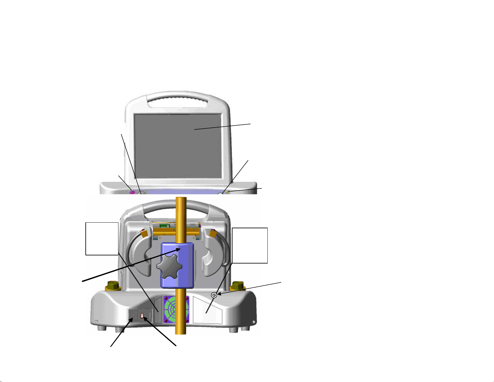
Section III. System Setup
Figure 1: Front Panel of ViOptix™Tissue Oximeter Console
Power ON
LED Indicator
LCD Brightness
Adjust Knob
IR Printer Port
Window
LCD Display and
Touch Screen
Startup/Shutdown
Power Button
Figure 1: Front Panel of T.OxTM Tissue O
Main
Rear Pan el
La b el
Fuse Label
AC power
input AC power ma ins ON/OFF s witch
(“1”=O N, “0” =OFF)
1” Po le holding fixture
Figure 2: Rear of ViOptix™Tissue Oximeter Console
Nurse call
alarm output
connector
(optional)
I.V. pole holding fixture

Operator’s Manual Page 15 of 89
OXY-2-USM-1, REV K
A. System Configuration
1. Connecting the T.Ox™ Tissue Oximeter
a. Plug the AC (alternating current) power cord into the back of the T.Ox™ Tissue Oximeter computer console module (see Figure
2).
b. Plug the AC power cord into a power source.
c. Place the back panel AC Power Switch to the ON (1) position
d. Attach sensor(s) to one or two channels’ connector(s).
e. Attach optional 10 foot nurse call alarm output cable from the nurse call output connector (refer to Figure 2) and an available
bedside nurse call system jack. To attach the cable, press the cable’s circular connector onto the rear panel connector and rotate
until it clicks and locks. To detach cable, pull back on the cable connector’s metal sleeve.
2. Turning on the T.Ox™ Tissue Oximeter
Turn on the T.Ox™ Tissue Oximeter by depressing the soft ON/Standby power button on the right front of the console. (Refer to
Figure 1) The main screen is displayed after console initialization and self-tests have been performed.
The power ON LED will flash slowly while the system is starting up.
Quick flashing of the power ON LED indicates the battery is being used during startup. Connect AC power to the console; otherwise
the battery will eventually be depleted.

Operator’s Manual Page 16 of 89
OXY-2-USM-1, REV K
3. Battery Operation
The console is not intended to be operated continuously under battery power. The battery will provide up to 30 minutes of normal
operation and is rechargeable but continuous use of the battery under low voltage conditions might damage the battery. If AC is
removed then use the battery to save logged data and power down the unit.
B. Using the T.Ox™ Tissue Oximeter Controls
1. AC Power Switch
The AC Power switch is on the back of the console. This switch routes AC power to the console’s power supply.
2. ON/Standby Button
Depressing the ON/Standby power button on the right front of the console applies power to, or removes power from, the console
electronics. (See Figure 1.)
To turn the unit off, hold the ON/Standby button in, then release it after 3 seconds. The console will perform a shutdown sequence and
then power off.
Note: If patient data was recorded but not saved before shutdown, the Oops Save Discard screen (Figure 3) will be displayed. This
screen requires the operator to take action (cancel shutdown, save, or discard the data) before the console powers off.
Operator’s Manual Page 17 of 89
OXY-2-USM-1, REV K
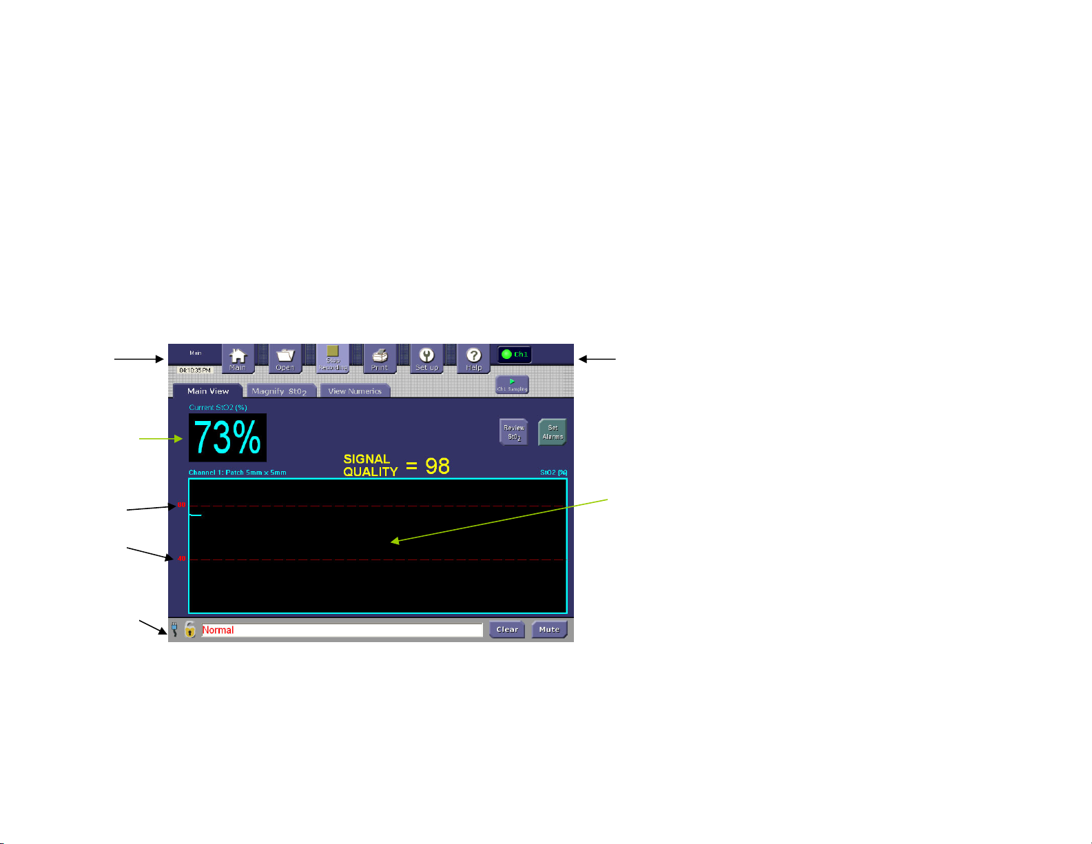
3. T.Ox™ Tissue Oximeter Monitor Screen Display
The main screen will appear after boot-up, as shown in
Figure 1. This illustration represents one-sensor/single-channel operation. The main T.Ox™ Tissue Oximeter monitor screen includes
these functional areas:
Control bar
Sensor verification
Numerical Data display
Tissue StO2trend graphs
Status & Alarms area (System Status)
Figure 1. Main Screen Functional Areas (Single Mode)
Sensor
verification
Tissue St02
trend graph
Control bar
Alarm
limits
(in red)
System status
bar
Numerical
data display
area
Operator’s Manual Page 18 of 89
OXY-2-USM-1, REV K
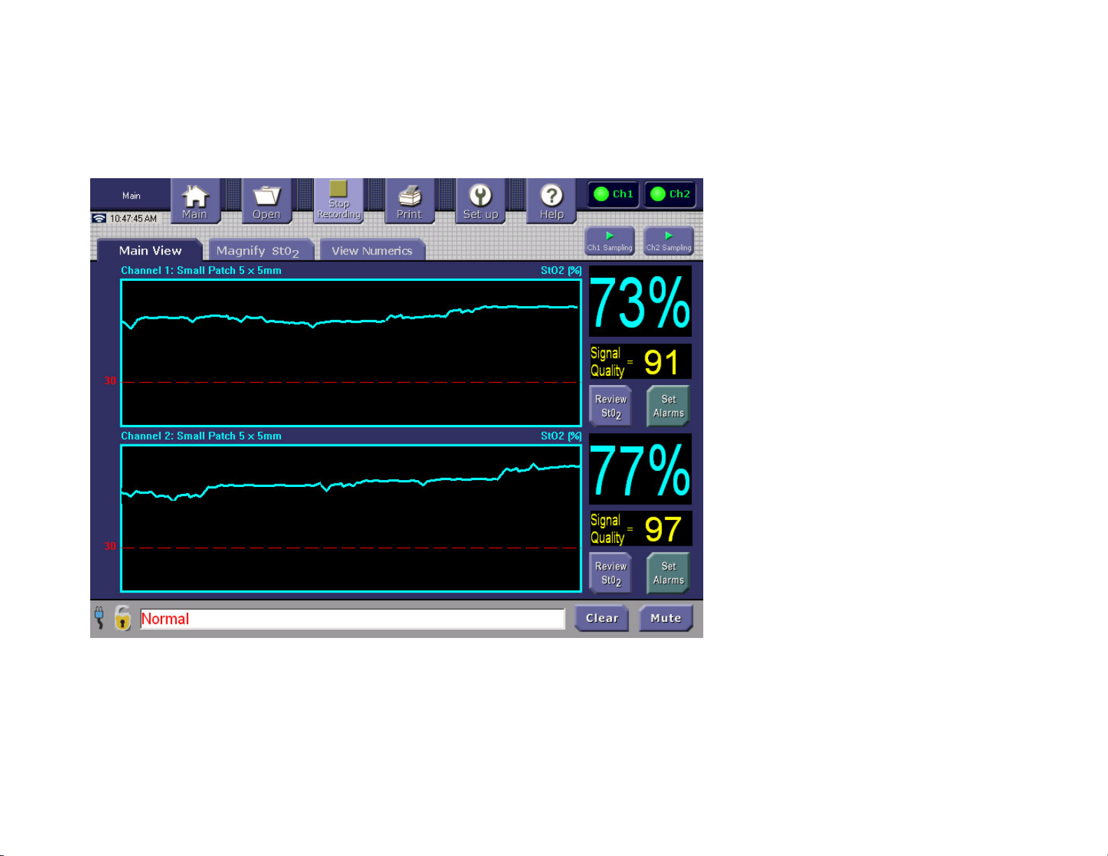
In two-sensor/dual-channel operation, the main screen provides separate sensor-verification indicators, Numerical Data displays, and
Tissue StO2trend graphs for each channel, as shown in Figure 2.
Figure 2. Main Screen Functional Areas (Dual Mode)
Operator’s Manual Page 19 of 89
OXY-2-USM-1, REV K
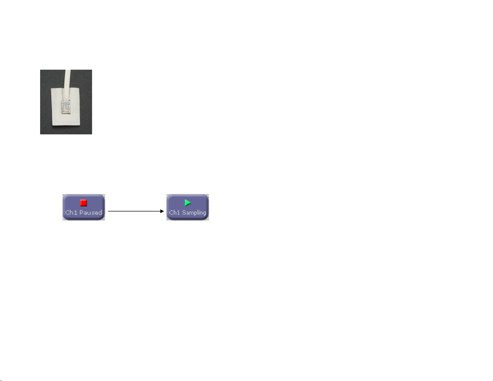
4. Patch Sensor Probe Acquisition
Small Patch Sensor
Note: During sampling, laser light will be emitted from two of the apertures in the sensor head. Avoid direct eye exposure.
Patch probe acquisition starts when the Main Screen’s channel Paused/Sampling button is activated to the Sampling position.

Operator’s Manual Page 20 of 89
OXY-2-USM-1, REV K
6. Recording Patient Data
When the Recording button is lighted (Stop Recording text displayed), the function is active and will log and save data while any
sampling is being performed. This is the default operating condition.
During channel data acquisition (sampling), the console logs the data in channel-specific temporary files. You can convert these files to
permanently-saved data files by tapping the Control Bar’s Stop Recording button and selecting Save in the Oops Save Discard screen.
Tapping the Stop Recording button will display the Oops Save Discard screen if any patient data has been acquired. This screen gives
the operator the option (Oops) to return to the previous screen, the option to discard the data or the option to save the data. Once the
data is saved or discarded the temporary data file is closed. When the operator saves the data in an operator-specified file, that data file
will be permanently saved in the console and available for review and off-loading using the Control Bar’s Open and Setup/Send files
buttons.
If the Stop Recording button is tapped and no patient data has been acquired, the console performs no operation and retains the current
screen.
You can review the current session’s StO2data from the Main Screen by tapping the appropriate channel’s Review StO2soft button.
Recording is used primarily for long-term monitoring; short-term monitoring may not require the recording of data. There are 200
Megabytes (MB) of disk storage area for logged data. The equivalent of three months of continuously recorded, two-channel data can
be stored and reviewed. Reference Recording a New File (Saving) for a description of file/data storage use and limitations.
The Main Screen Review StO2buttons become available only after data has been acquired. The console displays only the selected StO2
data logged at the time the Review StO2button is tapped. The console continues to log data while displaying the Review StO2screen.
To review the latest data the operator must return to the Main Screen and tap the Review StO2button again.
Table of contents
Other ViOptix Medical Equipment manuals

Popular Medical Equipment manuals by other brands


Medifa
Medifa 800200 Service manual

Siemens
Siemens Drager Medical Fabius GS Operator's instruction manual

Dermlite
Dermlite DL3 instructions

Denas MS
Denas MS DiaDENS PCM operating manual

Quest Engineering
Quest Engineering MPS 3 troubleshooting guide

Fresenius Medical Care
Fresenius Medical Care 2008T BlueStar Operator's manual