Viper ROS1300 User manual

Model No.: 50000605
55940533 / Rev. A / JUNE 2021
Original instructions
ROS1300
INSTRUCTION FOR USE


UK Declaration of Conformity
We,
Nilfisk Ltd
Nilfisk House, Bowerbank Way Gilwilly Industrial Estate
Penrith Cumbria
CA11 9BQ UK
Hereby declare under our sole responsibility that the
Product: FC - Floor Scrubber/Sweeper - Battery
Description: Charging mode: 220-240V 50-60Hz; Working mode: 24V DC, IP24
Type: ROS1300
Is in compliance with the following standards:
EN 60335-1:2012+A11:2014+A13:2017
EN 60335-2-72:2012
EN 61000-3-2:2019+A1:2021
EN 61000-3-3:2013+A1:2019
EN 61000-6-2:2019
EN 61000-6-4:2019
Following the provisions of:
Supply of Machinery (Safety) Regulations 2008/1597
Electromagnetic Compatibility Regulations 2016/1091
Penrith, 19-10-2021
Stewart Dennett
GM/MD

INSTRUCTION FOR USE ENGLISH
1
TABLE OF CONTENTS
INTRODUCTION ............................................................................................................................................ 2
GUIDE PURPOSE AND CONTENTS .............................................................................................................................................2
HOW TO KEEP THIS INSTRUCTION FOR USE ..........................................................................................................................2
DECLARATION OF CONFORMITY .............................................................................................................................................2
ACCESSORIES AND MAINTENANCE .........................................................................................................................................2
CHANGE AND IMPROVEMENT...................................................................................................................................................2
SCOPE OF APPLICATION .............................................................................................................................................................2
MACHINE IDENTIFICATION DATA ............................................................................................................................................2
TRANSPORT AND UNPACKING ..................................................................................................................................................3
SAFETY ............................................................................................................................................................ 3
VISIBLE SYMBOLS ON MACHINE ..............................................................................................................................................3
SYMBOLS THAT APPEAR ON THE INSTRUCTION FOR USE ................................................................................................3
GENERAL SAFETY INSTRUCTION .............................................................................................................................................4
MACHINE DESCRIPTION............................................................................................................................ 6
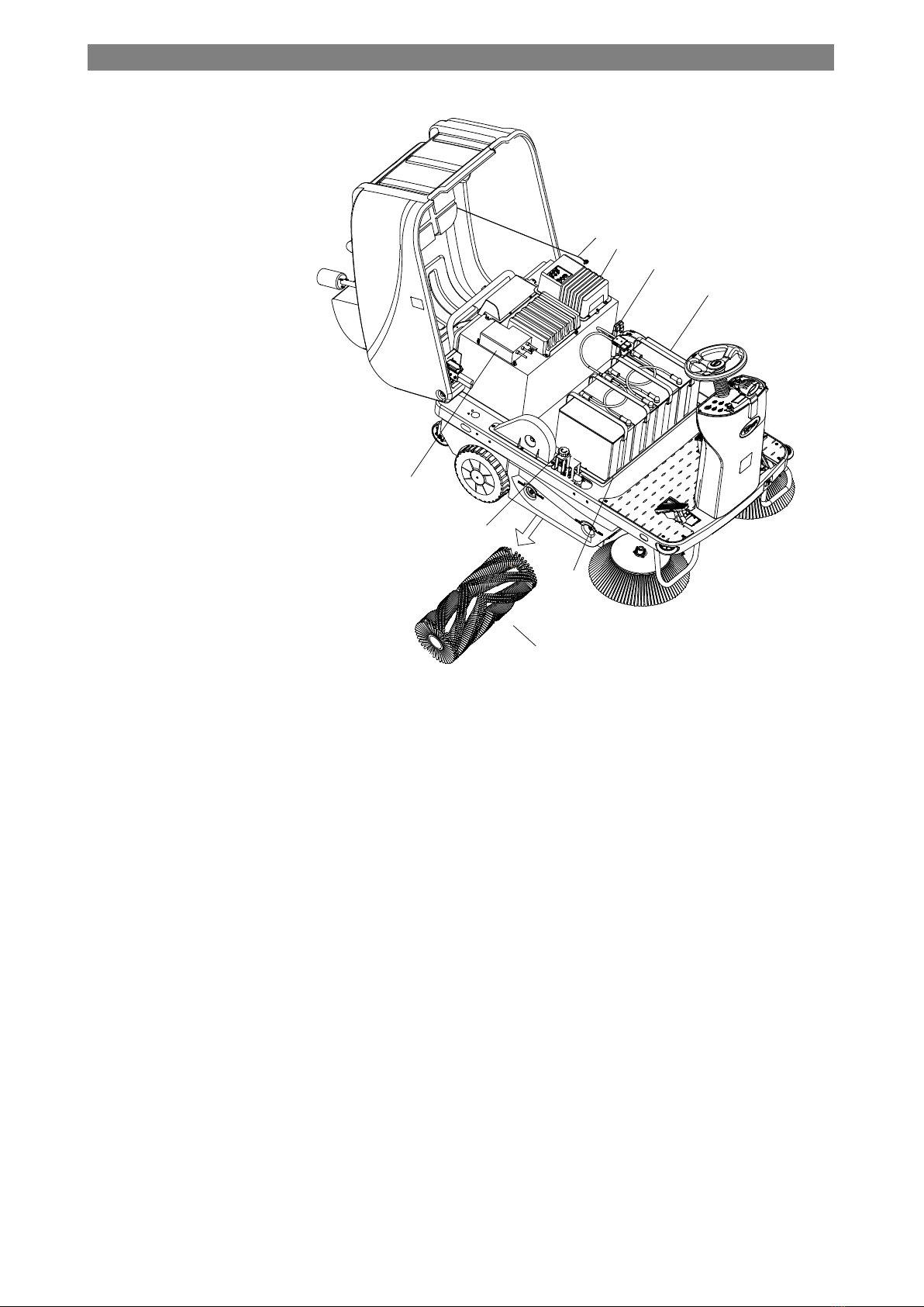
MACHINE STRUCTURE ................................................................................................................................................................6
CONTROL PANEL ..........................................................................................................................................................................8
WORKING MODE DESCRIPTION ................................................................................................................................................9
ACCESSORIES .............................................................................................................................................................................. 10
TECHNICAL DATA ...................................................................................................................................................................... 11
WIRING DIAGRAM ...................................................................................................................................................................... 12
OPERATING GUIDE .................................................................................................................................... 13
BATTERY CHECK/SETTING ON A NEW MACHINE .............................................................................................................. 13
BATTERY INSTALLATION AND BATTERY TYPE SETTING (WET /GEL/ AGM/ DIS/EXI/FUL/OPT/ENE(TPPL))......... 14
BEFORE MACHINE START-UP .................................................................................................................................................. 15
STARTING AND STOPPING THE MACHINE ........................................................................................................................... 16
PARKING BRAKE ......................................................................................................................................................................... 17
MACHINE OPERATION ............................................................................................................................................................... 17
HOPPER DUMPING ...................................................................................................................................................................... 18
SIDE BROOM INSTALLATION................................................................................................................................................... 18
WATER SPRAY FLOW SETTING ............................................................................................................................................... 19
AFTER USING THE MACHINE ................................................................................................................................................... 19
PUSHING/TOWING THE MACHINE .......................................................................................................................................... 19
MACHINE STORAGE DURING LONG INACTIVITY ............................................................................................................... 20
FIRST PERIOD OF USE ................................................................................................................................................................ 20
MAINTENANCE ........................................................................................................................................... 20
SCHEDULED MAINTENANCE TABLE ..................................................................................................................................... 20
BATTERY CHARGING ................................................................................................................................................................ 21
MAIN BROOM HEIGHT CHECK AND ADJUSTMENT ............................................................................................................ 22
MAIN BROOM REPLACEMENT ................................................................................................................................................. 23
SIDE BROOM HEIGHT CHECK AND ADJUSTMENT .............................................................................................................. 24
DUST FILTER CLEANING AND INTEGRITY CHECK ............................................................................................................. 25
BLADE HEIGHT AND OPERATION CHECK ............................................................................................................................ 26
WHEEL CHAIN CHECK AND ADJUSTMENT .......................................................................................................................... 27
TROUBLESHOOTING ................................................................................................................................. 27
ERROR CODE OF DISPLAY app: detail ................................................................................................... 28
SCRAPPING ................................................................................................................................................... 28

INSTRUCTION FOR USE ENGLISH
2
INTRODUCTION
NOTE
The numbers in brackets refer to the components shown in Machine Description chapter.
GUIDE PURPOSE AND CONTENTS
The purpose of this instruction for use is to provide the operator with all basic information and technical characteristics, operation,
machine inactivity, spare parts, and safety conditions etc.
Before performing any procedure on the machine, the operators and qualified technicians must read the Instruction for Use manual.
Contact our company in case of doubts concerning the interpretation of the instructions or for any further information.
HOW TO KEEP THIS INSTRUCTION FOR USE
The Instruction for Use must be kept near the machine, inside an adequate case, away from liquids and other substances that can cause
any damage to it.
DECLARATION OF CONFORMITY
Declaration of Conformity is supplied with the machine and certifies machine conformity with the law in force.
NOTE
The copies of the original Declaration of Conformity are provided together with the machine
documentation.
ACCESSORIES AND MAINTENANCE
All the necessary operation, maintenance and repair procedures must be made by qualified personnel, or our company appointed repair
center. ONLY original or approved spare parts and accessories can be used.
Contact our company’s customer service for any service or purchase of accessories or spare parts if necessary.
CHANGE AND IMPROVEMENT
We are committed to continuous improvement of our products, and the company reserves the right to machine changes and
improvements without additional information.
SCOPE OF APPLICATION
The machine applies to commercial and industrial use. It is suitable for cleaning smooth and solid floor, being operated by qualified
personnel in safe circumstances.
MACHINE IDENTIFICATION DATA
The machine serial number and model name are marked on the serial label.
This information is useful. Use the following table to write down the machine identification data when requiring spare parts for the
machine.
MACHINE MODEL
................................
................................
.....................
MACHINE SERIAL NUMBER
................................
................................
...

INSTRUCTION FOR USE ENGLISH
3
TRANSPORT AND UNPACKING
When the carrier delivers the machine, make sure the packaging and machine are both whole and undamaged. If any damage is observed,
inform the carrier of the damage before accepting the goods, to reserve the right to compensation for the damage.
Follow the instructions on packing strictly when unpacking the machine.
Check the package to ensure following items are included:
1. Technical documentation - Instruction for Use
2. Battery connection components
3. On-board charger manual (if installed) (*)
SAFETY
The following symbols indicate potentially dangerous situations. Always read this information carefully and take all necessary
precautions to safeguard people and property.
VISIBLE SYMBOLS ON MACHINE
WARNING!
Read all the instructions carefully before performing any operation on the machine.
WARNING!
Do not wash the machine with direct or pressurized water jets.
WARNING!
Do not use the machine to work on slopes with a gradient exceeding that is defined in the
specifications section.
SYMBOLS THAT APPEAR ON THE INSTRUCTION FOR USE
DANGER!
It indicates a dangerous situation with risk of death for the operator.
WARNING!
It indicates a potential risk of injury for people.
CAUTION!
It indicates a caution, or a remark related to important or useful functions.
Pay attention to the paragraphs marked by this symbol.
NOTE
It indicates a remark related to important or useful functions.
CONSULTATION
It indicates the necessity to refer to the Instruction for Use manual before performing any procedure.
max.
16%

INSTRUCTION FOR USE ENGLISH
4
GENERAL SAFETY INSTRUCTION
Specific warnings and cautions to inform about potential damages to people and machine are shown below.
DANGER!
•This machine must be operated by trained and authorized personnel according to guidance of the manual.
•Before performing any cleaning, maintenance, repair, or replacement procedure, read all the instructions carefully, ensure
the machine is OFF and disconnect the battery connector.
•Do not operate the machine near toxic, dangerous, flammable and/or explosive powders, liquids, or vapor. This machine is
not suitable for collecting dangerous powders.
•Do not wear jewelry when working near electrical components.
•Do not work under the lifted machine without supporting it with safety stands.
•When using lead (WET) batteries, they may emit inflammable gas under normal use, you must keep sparks, flames,
smoking materials and radiating, illuminating, and burning items away from the batteries.
•When charging lead (WET) batteries, they may emit hydrogen gas which may cause an explosion. You must ensure the
charging environment is well ventilated and away from flames.
WARNING!
•This machine is intended for COMMERCIAL USE, for example in hotels, schools, hospitals, factories, shops, and rental
businesses etc.
•Machines left unattended shall be secured against unintentional movement.
•To prevent unauthorized use of the machine, the power source shall be switched off or locked, for example by removing the
key to the main switch or the ignition key.
•Check the machine carefully before each use. Ensure that all the components have been well assembled. Loose components
may cause damage to people and properties.
•Never move the machine by pulling the battery charger cable. Do not pass the cable through a closed door or wind the cable
around sharp edges or corners. Do not run the machine over the battery charger cable. Keep the battery charger cable
away from heated surfaces.
•Do not charge the batteries if the battery charger cable or the plug are damaged.
•To reduce the risk of fire, electric shock, or injury, do not leave the machine unattended when it is charging. Before
performing any maintenance procedure, disconnect the battery charger cable from the electrical mains.
•The machine storage and working temperature must be between 0 °C and +40 °C, the humidity of air must be between 30%
- 95%.
•Do not use the machine on slopes with a gradient exceeding the specifications shown.
•Use brooms supplied with the machine or defined in the manual. Using other brooms could reduce safety.
•In case of machine malfunctions, ensure that these are not due to lack of maintenance. If necessary, request assistance from
the authorized personnel or from an authorized Service Center.
•Take all necessary precautions to prevent hair, jewelry, and loose clothes from being caught by the machine moving parts.
•Do not wash the machine with direct or pressurized water jets, or with corrosive substances.
•Do not bump into shelves or scaffoldings, especially where there is a risk of falling objects.
•Do not lean liquid containers on the machine, use the relevant can holder.
•To avoid damaging the floor, do not allow the broom to operate while the machine is stationary.
•In case of fire, use a dry powder fire extinguisher. Do not use liquid fire extinguishers.
•Do not remove or modify the machine labels.
•Do not tamper with the machine safety guards and follow the scheduled maintenance instructions closely.
•Pay attention during machine transportation when temperature is below freezing point. The water in the solution tank and
in the hoses could freeze and cause serious damage to the machine.

INSTRUCTION FOR USE ENGLISH
5
•If spare parts need be replaced, order ORIGINAL spare parts from an Authorized Dealers or Retailers.
•Return the machine to the Service Center if it doesn’t work as usual or is damaged.
•To ensure machine proper and safe operation, the scheduled maintenance shown in the relevant chapter of this manual,
must be performed by the authorized personnel or an authorized Dealer or Retailer.
•The machine must be properly disposed of, due to the presence of toxic-harmful materials (batteries, etc.), which are subject
to standards that require disposal in special centers (see Scrapping chapter).
•This machine is a cleaning tool only and is not intended for any other purpose.
•Always keep the openings free from dust, hairs and any other foreign material which could reduce the air flow. Do not use
the machine if the openings are clogged.
•Use the machine only where proper lighting is provided.
•Front light must be used only to enhance visibility on the floor to be cleaned, but it does not authorize anyone to use the
machine in dark environments.
•This machine is not intended for use by persons (including children) with reduced physical, sensory, or mental capabilities,
or lack of experience and knowledge.
•Close attention is necessary when used near children.
•Children should be supervised to ensure that they do not play with the machine.
•While using this machine, take care not to cause damage to people or objects.
•Operators shall be adequately instructed on the use of this machine.
•Do not use the machine without a falling object protective structure (FOPS) in areas where it is likely that the operator
could be hit by falling objects.
•Always protect the machine against rain, and bad weather, under both operating and inactivity conditions. Store the
machine indoors, in a dry environment: this machine must be used in dry conditions and must not be used or kept outdoors
in wet conditions.
•Adjust the operation speed to suit the floor conditions.
•Avoid sudden stops and drive at low speed when the machine goes downhill. Avoid sharp turns.
•This machine cannot be used on roads or public streets.

INSTRUCTION FOR USE ENGLISH
6
MACHINE DESCRIPTION
MACHINE STRUCTURE
1. Tank cover
2. Solution tank (*)
3. Turn indicator
4. Air outlet bracket
5. Filter compartment cover
6. Knurled knob
7. Hopper
8. Latch
9. Hopper rear wheel
10. Steering wheel
11. Solution tank
12. USB charging port
13. Phone bag
14. Accelerator pedal
15. Machine lift anchor
16. Chassis
17. Right cover
18. Side blade
19. Drive wheel (with
mechanical brake)
20. On-board charger plug (*)
21. External charger connector
22. Warning light
23. Adjustable seat (with safety
switch)
24. Blue light (*)
25. Logo label
26. Headlight
27. Spray nozzle
28. Side broom
29. Right bumper
30. Solution valve
31. Cover
32. Cup holder
33. Left cover
34. Flap pedal
35. Parking brake
36. Left bumper
37. Front blade
38. Front wheel
Figure 1
Figure 2
13
17
21
14
18
11
15
19
12
16
20
1
5
4
8
9
3
7
2
6
10
23
27
32
35
38
24
28
15
28
25
29
30
33
36
26
31
22
34
37

INSTRUCTION FOR USE ENGLISH
7
39. On-board charger (*)
40. Main broom adjuster
41. Hood support cable
42. Circuit breaker box
43. Battery connector
44. Battery (*)
45. Battery tray
46. Main broom
Figure 3
40
44
41
45
42
46
39
43

INSTRUCTION FOR USE ENGLISH
8
CONTROL PANEL
47. Multifunction display
Items displayed:
A) Pump/Vacuum motor/Side-broom separate
running mode
B) One-button start mode
C) Safety stop mode (seat safety switch off)
D) Reverse mode
E) Braking/parking mode
F) Battery charging mode
G) Pump working
H) Vacuum motor working
I) Side broom working
J) Battery type
K) Battery level
L) Runtime (Hour meter)
M) Pump off-working
N) Vacuum motor working
O) Main broom working
P) Side broom working
Q) Filter shaker off-working
48. Speed adjusting knob
49. Vacuum button
‧ Turn on/off the vacuum motor
50. Pump button
‧ Turn on/off the pump
51. Side broom button
‧ Turn on/off the side broom
52. Filter shaker button
‧ Turn on/off the filter shaker
‧ Press for 1 second to switch to Auto cleaning
mode (LED of filter shaker flashes) and press
for 1 second again to exit.
53. One-button start button
‧ Turn on/off all vacuum motor, main broom
and side brooms
54. Forward-reverse button
55. Horn button
56. Ignition key (I=ON, O=OFF)
57. Side broom speed adjusting knob
58. Headlight button
‧ Turn on/off the headlight
‧ Press for 1 second to turn on/off the blue light
(if equipped)
59. Left-turn indicator button
60. Right-turn indicator button
61. Emergency stop button
62. F8 side broom (L) motor circuit breaker (10A)
63. F9 side broom (R) motor circuit breaker (10A)
64. F7 main broom motor circuit breaker (30A)
65. F11 vacuum motor circuit breaker (10A)
66. F6 main controller circuit breaker (5A)
67. F10 filter shaker motor circuit breaker (10A)
68. F5 controller power fuse (150A/70VDC)
Figure 4
Figure 5
NOTE
(Circuit breaker maintenance see
Troubleshooting chapter)
LKJ
Q
P
O
N
IH
GM
51
57
50
58
49
47
53
59
48
54
55
52
56
61
60
GEL
D
A B
GEL
0000.H
OFF.
GEL
C
P
0000.H
0000.H
GEL
R
0000.H
stop
F
E
68 67 66 65
646362

INSTRUCTION FOR USE ENGLISH
9
WORKING MODE DESCRIPTION
HOW TO OPERATE DISPLAY DESCRIPTION
Standby mode
–Key (56) on
–Seat safety switch (23) on
–One-button start (53) off
1. The point in the hour meter does
not flash.
2. LCD only displays battery type,
battery level and runtime.
3. All pump, vacuum motor, filter
shaker, main and side brooms
functions are off. (Vacuum motor
will be off in several seconds if it
is on.)
One-button start mode
–Key (56) on
–Seat safety switch (23) on
–One-button start (53) on
1. The point in the hour meter does
not flash.
2. The tap water drop icon does not
display.
3. The fan icon does not rotate.
4. Filter shaker icon displays
“OFF”.
5. Main and side broom arrow icon
does not rotate.
–Key (56) on
–One-button start (53) on
–Seat safety switch (23) on
–Accelerator pedal (32) pressed
1. The point in the hour meter
flashes.
2. The tap water drop icon does not
display.
3. The fan icon rotates.
4. Filter shaker icon displays
“OFF”.
5. Main and side broom arrow icon
rotates.
Separate running mode
–Key (56) on
–Seat safety switch (23) on
–One-button start (53) off
–Vacuum button (49) / pump
button (50) / side broom button
(51) / filter shaker button (52) on
–Accelerator pedal (32) pressed
1. The point in the hour meter
flashes.
2. The tap water drop icon flashes.
3. The fan icon rotates. (If filter
shaker is on, vacuum motor will
be off.)
4. Side broom arrow icon rotates.
Reverse mode
–Key (56) on
–Seat safety switch (23) on
–Forward-reverse button (54) on
Horn sounds for reverse warning
GEL
0000.H
OFF.
0000.H
GEL

INSTRUCTION FOR USE ENGLISH
10
HOW TO OPERATE DISPLAY DESCRIPTION
Braking/parking mode
– Key (56) on
– Seat safety switch (23) on
– Mechanical parking brake (35)
pressed
Machine stops moving. Other
functions remain in their original
state.
Safety stop mode
– Key (56) on
– Seat safety switch (23) off
(Operator leaves the seat of the
machine)
1. “STOP” icon alternates with the
status bar on the screen.
2. All functions are shut down
except for horn and light control.
Charging mode
– Connect charger plug to power
supply
1. LCD displays charging status.
2. All functions are shut down.
Power off mode
– Key (56) off
– Or emergency stop button (61)
on
1. The power is cut off.
2. LCD is off.
Note: Before turning off the key
(56), turn off the one-button start
(53) and wait for the broom to rise
to the fully up position.
ACCESSORIES
The following accessories are optional:
1. WET/GEL/AGM/TPPL batteries
2. Battery charger
3. Main and side brooms with harder or softer bristles
4. Blue light
5. Overhead guard
6. Rear mounted solution tank
For further information concerning the optional accessories, contact an authorized retailer
P

INSTRUCTION FOR USE ENGLISH
11
TECHNICAL DATA
Parameter
Value
Machine length
1,680 mm /66.1 Inches
Machine width (without side brooms)
1
,
055 mm /41.5 Inches
Machine maximum height
1
,
300 mm /51.2 Inches
Cleaning width (without side brooms)
700 mm /27.6 Inches
Cleaning width (with two side brooms)
1
,
350 mm /53.1 Inches
Minimum distance from the floor (blades not included)
60 mm/2.4 Inches
Main broom size (diameter x length)
300x700 (mm) / 11.8x27.6 (Inches)
Side broom diameter
500 mm/19.7 Inches
Main broom speed
600 rpm
Side broom speed
0~98 rpm
Front wheel specific pressure on the floor
0.88 N/mm
2
Rear wheel specific pressure on the floor
0.6 N/mm
2
Machine weight
(without batteries)
361 kg/794.2 Lbs.
Gross vehicle weight (GVW)
6
88
kg/
1516.8
Lbs.
Shipping weight
495 kg/1089 Lbs.
Shipping size
1810x1180x1500(mm) / 71.3x46.5x59.1
(Inches)
Hopper capacity
130 L/34.3 Gal.
Main broom motor
Input 624 W Output 500 W
/ Input 0.85 HP Output 0.68 HP
Side broom motors
Input 280 W Output 100 W / Input 0.38 HP Output 0.14 HP
Drive system motor
Input 936 W Output 650 W / Input 1.2 HP Output 0.88 HP
Vacuum system motor
Input
168 W Output 139 W/ Input 0.23 HP Output
0.19 HP
Filter shaker motor
Input 144 W Output 100 W / Input 0.2 HP Output 0.14 HP
Rated Power
2640 W/3.6 HP
Power consumption
950 W/1.3 HP
Sound pressure level at workstation
(ISO 11201, ISO 4871) (LpA) 72 ± 3 dB(A)
Machine output acoustic power
(ISO 3744, ISO 4871) (LwA) 86 ± 3 dB(A)
Vibration level at the operator’s arms (ISO 5349
-
1) (*)
<2.5 m/s
2
Vibration level at the operator’s body (ISO 2631
-
1) (*)
<1.5 m/s
2
IP protection class
IP 24
(*) Under normal working conditions, on a level asphalt surface.
Performance
Value
Maximum forward speed
8 km/h /5 Miles per hour
Maximum reverse speed
4 km/h / 2.5 Miles per hour
Gradeability (transport mode only) Max.
20%
Gradeability (working mode) Max.
16%
Min. turn
-
around aisle width
2550
mm/100.4 Inches
Battery
Value
Battery voltage
DC 24 V
Battery compartment inner size (length x width x height)
762 x 330 x 370 (mm)/ 30x13x14.6 (Inches)
Vacuuming and filtering
Value
Dust filter
3.5 m
2
/ 37.7 ft
2
Main broom compartment
vacuum
8.8 mm H
2
O
Filter shaker
Electric

INSTRUCTION FOR USE ENGLISH
12
WIRING DIAGRAM
1
1
2
2
3
3
4
4
5
5
6
6
7
7
8
8
D D
C C
B B
A A
B-
B-
EB2
Main Controller
B+
B-
B+
B-
Traction+
Traction-
KA1 EM Brake
C16-1
C16-2
P1-1
P1-2
WHI
WHI WHI
WHI
F7
Circuit Breaker 30A
M
M3
Traction Motor
M
W
M9
ater Pump
B-
TO 1A5 +24V OUT Brush+
Brush-
C17-1
C17-2
M
M4 Main Brush Motor
F8
Circuit Breaker 10A
B-
+24V OUT
Side Brush+
Side Brush-
C18-1
C18-2
M
M5 Left Side Brush Motor
F9
Circuit Breaker 10A
C19-1
C19-2
M6 Right Side Brush Motor
M
C20-1
C20-2
F10
Circuit Breaker 10A
B+
B-
B+
B-
P2-3
P2-10
Warning Lamp
C21-1
+24V OUT
C21-2
B-
P2-8
P3-7
C7-1
C7-2
+
-
HALL
VO
Pedal
GND
C14-1
C14-5
C14-2
C14-3
C14-4
SW5 C13-1
C13-2
SW4
GND
P2-7
P3-10
P3-4
P3-5
GRY
ORG
RED
BLK
BLK
BU/BK
RED
BT1
DC 24V
F5
FUSE 150A
K1
Main Contactor 24V
K1
P3-8
P3-17
24V+
BAT-
BAT+
F6 Circuit Breaker 5A
SW2
Key Switch
Brake Signal
Seat Signal
Accel Wiper
Move Enable
Brake+
Brake-
+24V Input
CAN-H
CAN-L
VIN+
VR1
BU/BK
WHI
CAN-H
CAN-L
VIN
GND
GND
J5-2
J5-3
J5-4
J5-1
P4-2
P4-3
P3-18
J9-3
J9-1
P2-6 Slow Down Sensor 1
POT High
Speed Limit ADJ
SPK1
BUZZER
C4-1
C4-2
B-
RED
BLK
BRN
BLU
Left
Right
C3-3
+24V
+12V
+12V
GND
+12V
USB Charger
EB3 J7-5
GND
+24V Out
J4-5
J4-1
J6-1
J6-2
Comment
RED-Red1
2
3
4
5
6
7
8
9
10
BLK-Black
BRN-Brown
WHI-White
GRN-Green
BLU-Blue
YEL-Yellow
PUR-Purple
ORG-Orange
GRY-Grey
11
12
13
14
15
16
17
18
19
20
RD/BK-Red and Black
BN/BK-Brown and Black
YE/BK-Yellow and Black
PU/BK-Purple and Black
BU/BK-Blue and Black
GR/BK-Green and Black
OR/BK-Orange and Black
C1-C21 Wire To Wire Connectors
EB1
DashBoard
5V 0.8A Max
BRN
WHI
RED
BLK
RED
RED
BLK
RED
YEL
YEL
+24V
TO 1A5
BRN
BLK
BRN
BRN
BLK
BRN
BLU
RED
RED
YEL
BLU
GRN
BLK
BLK
BLK
BLK
GRN
BLK
RED
BLK
POT Low
J9-2
GR/BK
RD/BK
RED
BLK
YE/BK
RED
BLK
ORG
YEL
ORG ORG
YEL
RED
BLK
BLK
BN/BK
BLK BLK
RED
BLK
RED
RED
BLK
SW1
Emergency Stop
M
M1
Main Brush Actuator
C5-1
C5-2
M
M2
Side Brush Actuator
C6-1
C6-2
BRN
BLU
BLK
RED
BAT+
VR2
BU/BK
WHI
J8-3
J8-1
POT High
Side Brush ADJ
POT Low
J8-2
GR/BK
M
M7 Fliter Shaker Motor
KDS KCCA0379
GND
+24V
+24V
C10-2
C10-1
BAT+
Headlight
C3-2
C1-1
J4-4
+24V
J4-2
(Optional)
BAT+
B+
B-
B+
B-
B+
B-
B+
B- F3 PTC 1.85A
F2 PTC 1.85A
To Side Brush Actuator
To Main Brush Actuator
LED1
LED3
LED4
J7-6
J7-1
J7-4
J2-4
J2-8
J2-1
TO 1A5
TO 1A5
P3-15 Charger Signal
RED
F4
PTC 1.85A
BAT+
J2-3
TO 1A5
J7-3 Pump Out
C12
Without Inner Charger Version,
P3-15 is Open.
AC
+-
DC
CAN-H
CAN-L
NO
CH1
Battery Charger
M
M8
Suction Motor
CH_Signal&Power J2-2
GND
F11
Circuit Breaker 10A
BAT+
Daughter
C15-1
C15-2
Speed
Board
TO 1A5
SQ1
COM
NO
+
-
External Charger
RED
BLK
Connector
RED
RED
BLK
C11
SW3
External Charger
Input Sensor
NC
C8-1 C8-2
PUR PUR
PUR
C9-1
C9-2
YEL
BU/BK
J2-7 B-
BRN
BLU
REDRED
BLU BRN
BRNBLU
RD/BK
RD/BK
RED
YEL
BLU
BU/BK
YEL
RED
BLK
RD/BK
RD/BK RD/BK
RED
RED
RED
BLK
RD/BK
BN/BK
C3 C3-1
GND
BLK
BLK
BLK BLK
Blue Light(Optional)
C1-2
C2-1
C2-2
LED2
BLK
REDRED
BLK
LED5
J4-3
J12
J13
J15
J18
SW6 C22-1
C22-2
Solution Sensor
BRN
P3-2
BLU
BLK
BLK BLK
12
NTC 25C= 100K
C24-1
C24-2
GRY
GRY
GRY
GRY
B- P2-14
Te mp S en so r
WHI
Speed Pluse
Speed Pluse
Speed Pluse J12-2
C23
TO 1C3
TO 1D4
(Optional)
WHI
WHI
BAT-

INSTRUCTION FOR USE ENGLISH
13
OPERATING GUIDE
WARNING!
On some points of the machine there are some labels indicating:
– DANGER!
– WARNING!
– CAUTION!
– CONSULTATION
While reading this Manual, the operator must pay attention to the symbols shown on the labels. Do not cover these labels for
any reason and immediately replace them if damaged.
BATTERY CHECK/SETTING ON A NEW MACHINE
WARNING!
The electric components of the machine can be seriously
damaged if the batteries are either improperly installed or
connected. The batteries must be installed by qualified
personnel only. Set battery type using the procedures
below according to the type of batteries used (WET or
GEL/AGM/DIS/EXI/FUL/OPT/ENE(TPPL). Check the
batteries for damage before installation. Disconnect
battery connector and battery charger plug. Handle the
batteries with great care. Install the battery terminal
protection caps supplied with the machine.
NOTE
The machine requires four 6V batteries, connected and
installed in the positions shown in Figure 6.
Batteries already installed on the machine
1. Ensure that the battery connector is connected.
2. When first using the machine with new batteries, perform a full charging
cycle (see the procedures in Maintenance chapter).
Without batteries
1. Buy appropriate batteries (see “Technical Data” chapter). For battery
choice and installation, contact qualified battery retailers.
2. Set battery type according to the procedures below.
Figure 6

INSTRUCTION FOR USE ENGLISH
14
BATTERY INSTALLATION AND BATTERY TYPE SETTING (WET /GEL/ AGM/
DIS/EXI/FUL/OPT/ENE(TPPL))
Battery Installation
1. Make sure that the machine is turned off with the ignition key and the parking brake is engaged.
2. Tip back the cover (31, Figure 2) carefully.
3. The machine is equipped with battery cables suitable for installing 4X6V batteries. Carefully put the batteries into the
compartment, then install them correctly.
4. Route and install the battery cables as shown in (Figure 6), then carefully tighten the nut on each battery terminal.
5. Place the protection cap on each terminal, and then connect the battery connector to the connector on the machine.
6. Turn back the cover carefully.
Battery type setting (WET/GEL/AGM/DIS/EXI/FUL/OPT/ENE(TPPL))
Access to select battery mode
According to the type of batteries (WET/GEL/AGM/DIS/EXI/FUL/OPT/ENE(TPPL)), set up the machine as follows:
7. Press vacuum button (A, Figure 7) and
pump button (B, Figure 7) at the same
time.
8. Insert ignition key (C, Figure 7) and turn
it to "I".
9. Several seconds later the system enters
select battery mode (Figure 7).
10. Release both vacuum button (A, Figure 7)
and pump button (B, Figure 7).
11. Press vacuum button (A, Figure 7) and
pump button (B, Figure 7) to select
battery type (E, Figure 7).
12. Press headlight button (D, Figure 7), about 1 second later the screen displays "Update OK", indicating that battery type is set up,
then restart machine. (C, Figure 7).
Battery charging
Fully charge the batteries (see the procedures in Maintenance chapter).
Battery discharging
1. When the battery icon displays full battery level (G, Figure 8), the batteries are fully charged.
2. When the battery icon displays low battery level (H, Figure 8), the batteries must be charged. Several seconds after the low
battery level is displayed, the Main broom/Side broom/Vacuum/Pump/Filter shaker motors are automatically turned off, while
the drive system remains on. Drive the machine to the designated charging area to charge immediately.
3. When battery voltage is very low, an error warning “Battery VOL Low” (I, Figure 8) will flash on the screen. Main broom/Side
broom/Vacuum/Pump/Filter shaker motors are automatically turned off, and the drive system is also turned off to protect the
batteries.
Figure 8
G
H
I
D
C
B
E
Panel Setting
Cust
1 Battery Type
Value : 4 -GEL
Access to select battery mode
A
Figure 7

INSTRUCTION FOR USE ENGLISH
15
BEFORE MACHINE START-UP
Checklist
1. Have a full knowledge of the machine operating controls and
their functions.
2. Sit on the seat (A, Figure 9), insert the ignition key (C, Figure
9), and start the machine. (See the procedures in the following
paragraph)
3. Check the battery level. If the battery icon on the LCD (G,
Figure 9) is of 5 bars, the batteries are fully charged for use. If
it is of 1 bar or less, batteries must be charged before operation.
(Refer to Maintenance chapter for battery charging)
4. Check the parking brake (F, Figure 9). The brake must hold its
setting (locked) firmly without easily being released (report all
defects immediately to Nilfisk Service Center).
5. Check the flap pedal (E, Figure 9) for proper operation.
6. Press the accelerator pedal (D, Figure 9) slightly then release it
to check if the machine can be steered forward and stopped.
7. To ensure safety, confirm the machine can be stopped
immediately when pressing the emergency stop button (B,
Figure 9). Turn the emergency stop button to reset it.
WARNING!
If the pedal is “spongy” or fades under pressure
without an efficient braking force, do not drive
the machine (report all defects immediately to
Nilfisk Service Center).
8. Make sure that there are no open covers/hoods and that the
machine is in normal operating conditions.
9. Make sure that the hopper (H, Figure 9) is properly closed.
Cleaning planning
1. Arrange long runs with a minimum of stopping or starting.
2. Allow a small amount of broom path overlap to ensure complete coverage.
3. Avoid making sharp turns, bumping, or scraping the side of the machine.
GEL 0000.H0000.H
GEL
H
G
F
E
D
C
B
A
Figure 9

INSTRUCTION FOR USE ENGLISH
16
STARTING AND STOPPING THE MACHINE
Preliminary operations
1. Sit on the driver’s seat (A, Figure 10) and adjust its position with the lever (C, Figure 10) to allow easy reach of all controls.
NOTE
The driver’s seat (A, Figure 10) is equipped with
a safety sensor, which allows the machine to be
driven only when the operator is on the driver’s
seat.
Starting the machine
1. Sit on the seat (A, Figure 10), insert the ignition key (J, Figure
10), and turn it to “I”.
2. Disengage the parking brake and drive the machine to the
working area.
3. Press one-button start button (M, Figure 10) to start the machine,
the side brooms and main broom are lowered to the floor
automatically.
4. Press the accelerator pedal (E, Figure 10), drive the machine
forward or backward with steering wheel (B, Figure 10) and
forward-reverse button (L, Figure 10). Driving speed can be
adjusted with speed adjusting knob (N, Figure 10). Main/side
brooms and vacuum motor begin to work.
5. Adjust side broom speed with side broom speed adjusting knob
(I, Figure 10) based on cleaning requirements.
6. The USB charging port (D, Figure 10) can be used to charge
mobile phone or pad when ignition key (J, Figure 10) is turned to
“I”.
7. Press the horn button (K, Figure 10) to warn people when
necessary.
NOTE
The main broom and side brooms (F and H,
Figure 10) can be lowered and lifted even when
the machine is moving.
The main broom and side brooms do not rotate
when they are lifted.
8. Start sweeping by turning the steering wheel (B, Figure 10) and
driving the machine forward with the accelerator pedal (E, Figure
10).
Stopping the machine
9. Release the accelerator pedal (E, Figure 10), and the machine stops moving.
10. Press one-button start button (M, Figure 10) again to turn off brooms, vacuum motor and pump. The main broom and side brooms
are lifted from the floor automatically. The vacuum system is turned off after a delay of several seconds.
11. Turn the ignition key to “O”.
12. Engage the parking brake.
Figure 10
F
H
F
K
IL
A
O
E
N
D
M
C
J
B
G

INSTRUCTION FOR USE ENGLISH
17
PARKING BRAKE
1. Engage the parking brake by pressing on the front of the pedal (A, Figure
11) and engaging the lever (B, Figure 11).
2. Disengage the parking brake by pressing on the back of the pedal (C,
Figure 11) and releasing it.
WARNING!
Before performing any maintenance, repair, cleaning or
replacement procedure, engage the parking brake.
Don’t park the machine on a ramp.
MACHINE OPERATION
WARNING!
When using the machine on slopes, follow the maximum gradient values marked on the machine (see
“Technical Data” chapter).
WARNING!
Pay careful attention when operating the machine at high speed: sudden steering could cause this three-wheel
machine to become unstable due to weight distribution. Always reduce the speed before steering.
1. Drive the machine to the work area as shown in the previous paragraph.
2. Drive the machine straight forward at high speed. Drive the machine slower when sweeping a large amount of dust or debris or
when safe operation requires slower speed. To achieve optimal results, overlapping sweeping paths by over 10 cm (4 inches) is
recommended.
3. Avoid stopping the machine in the same position for a long time with the brooms rotating: this could create unwanted marks on
the floor.
4. To collect light and bulky waste materials, lift the front blade by pressing the flap pedal (H, Figure 10); take into consideration
that the machine vacuum capability is reduced when the front blade is lifted.
CAUTION!
When operating on wet floors, it is essential to turn off the vacuum system by pressing the vacuum button (A,
Figure 12) to prevent the dust filter from being damaged.
5. For machine proper operation, the dust filter must be as clean as possible. To
clean it while sweeping, turn on the filter shaker by pressing the filter shaker
button (B, Figure 12).
During this operation the vacuum motor is automatically shut off.
After cleaning the filter, the vacuum system resumes working automatically;
then start sweeping again.
While working, “filter auto cleaning” mode can be activated by pressing filter
shaker button (B, Figure 12) for 1 second, which can repeat the filter cleaning
procedure every 10 minutes on average (depending on the dustiness of the
area to be cleaned, interval can be set from 1 to 60 minutes, parameter setting
refer to the Service Manual).
NOTE
This procedure can also be performed when the machine is
moving.
CAUTION!
When the dust filter is clogged and/or the hopper is full, the machine cannot collect dust and debris anymore.
6. The hopper (D, Figure 13) should be emptied after each working cycle and whenever it is full (see the procedure in the following
paragraph).
B
C
A
Figure 11
B
A
Figure 12
This manual suits for next models
1
Table of contents
Other Viper Blower manuals
Popular Blower manuals by other brands

EINHELL Expert
EINHELL Expert GE-EL 1800 E Original operating instructions

Elektror
Elektror SD Series Operating and assembly instructions

Ryobi
Ryobi RY09053 Operator's manual

DCS
DCS HBD1200E installation instructions

Black & Decker
Black & Decker GWC1815 Original instructions

Tennant
Tennant S7 Operator's manual