Virgo VRG22PL User manual

USER MANUAL
VRG14PL / VRG22PL
this product is certified:

IMPORTANT: Please keep the original packaging in
case you need to return the material. If we receive the
system in non-original packaging, the warranty will be
void.
IMPORTANT:The latest version of the VIRGO software
is available on our websites
or ,section “Download”.

I N D E X
.....................................................................page 3
.....................................................................................page 5
....................................page 6
...............................................................................page 8
.........................................page 8
.................................................................................page 9
................................................page 10
.................page 11
.............................................................page 13
................................................................................page 13
.....................................page 13
.............................................................................................page 14
........................................................................................page 15
...........................................................................................page 20
...................................................................................page 20
.............................................................................page 21
........................page 22
.................................................................page 22
................................................................................page 20
...............................................................................page 23
....................................................................page 23
....................................page 23
...................................................................................................page 26
........................................................................page 26
................................................................................page 27
.................................................................................page 28
..............................................................................page 30
...................................................................page 30
....................................................................page 31
...........................................................................................page 32
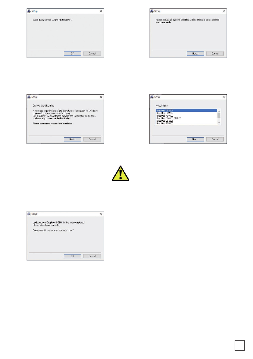
How to install the cutting plotter
System requirements
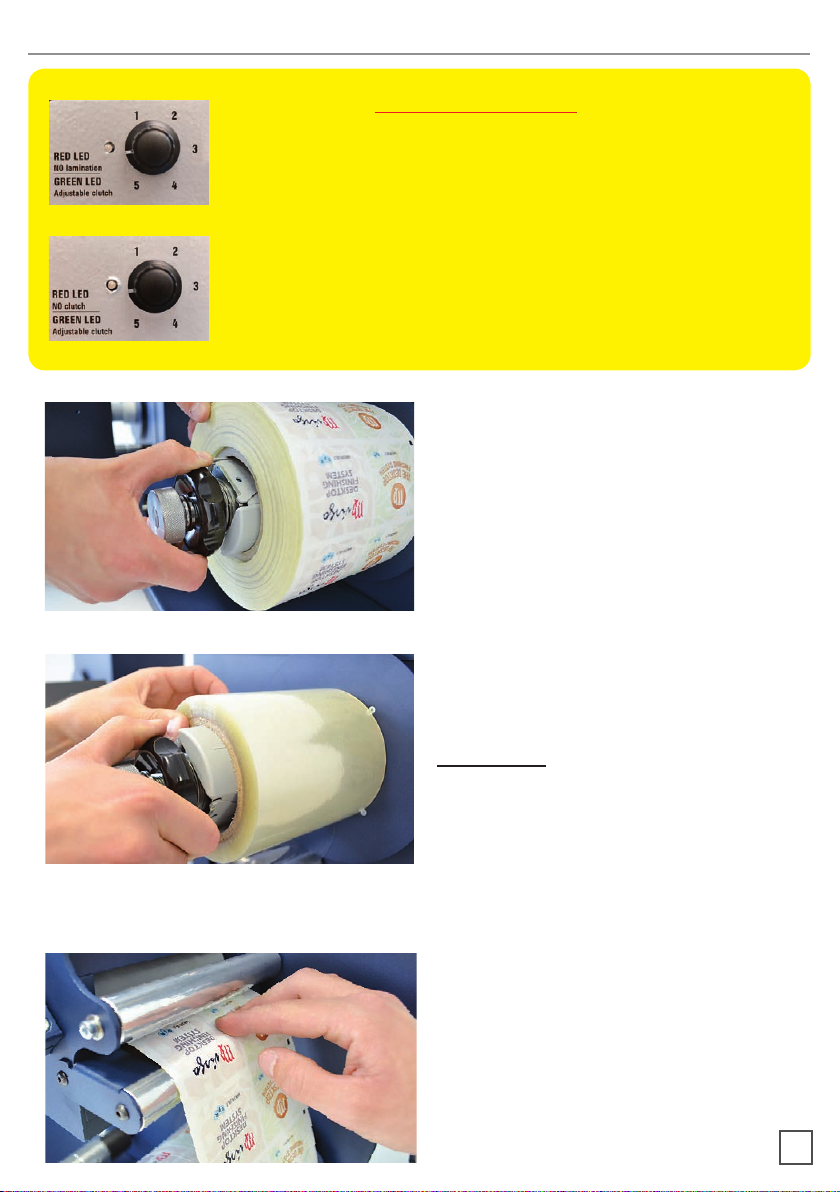
How to load and operate with the lamination module
How to adjust the clutch
How to load the laminated media into the plotter
How to run the cut test
How to load the matrix remover core holder
How to load the rewinder core holder and set the slitter module
How to add or remove blade holder
Metal guides alignment
Remove unwanted waste from the edge of the roll
VIRGO CUTTING MANAGER
User interface
Advanced options
Error Messages
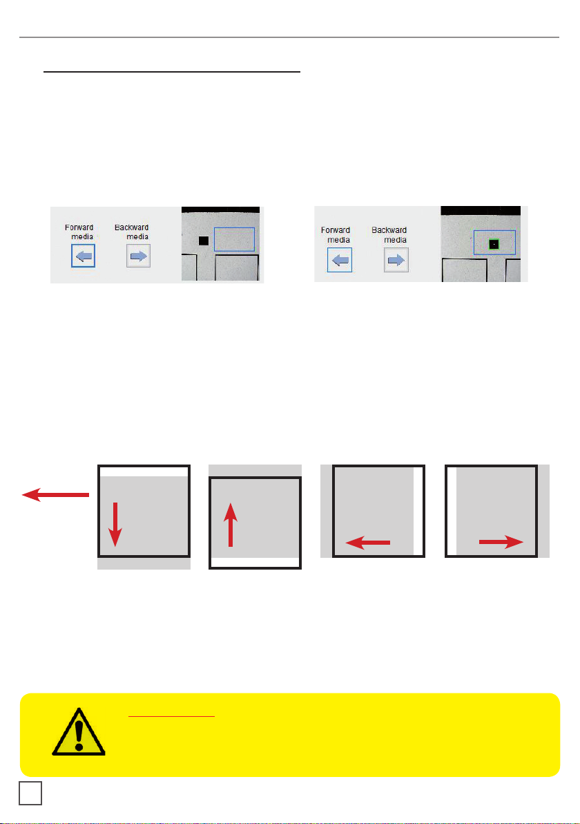
Black-mark detection
Black-mark position in the media
How to cut blank labels
How to update software
How to restore plotter settings
When and how to reduce the plotter feeding speed
Media path
Ultrasonic sensor calibration
Modules speed rotation
Graphtech mantenaice
How to replace the knife
How to replace the slitter blade
How to replace the cutting mat
Troubleshooting
2

HOW TO INSTALL THE CUTTING PLOTTER
1. Click on “SetupVirgoCM...” and follow
the step by step instructions to complete
the installation.
Please DO NOT connect the Virgo USB
to your pc before the installation is
complete
2. Click NEXT 3. Click NEXT
4. Click YES 5. In process
3
6. Click NEXT 7. Click FINISH

4
8. Click OK 9. Click NEXT (Remove the Virgo USB
from your pc, and turn o the Virgo)
10. Click NEXT 11. Choose the right model name of your
graphtec.
DO NOT CONFUSE “Graphtec CE6000”
WITH “Graphtec CE6000Plus”.
Click NEXT
12. Wait until the sign “Update for
the Graphtec CE6000 driver was
completed” shows up. You may need to
restart the computer.
Click OK
The installation is completed. A VirgoCM shortcut is displayed on your desktop

5
Plug in the USB camera and the USB dongle, they will auto-install.
If your computer already has a camera installed, we recommend disabling it. If you
do not, your pc will ignore the camera on the plotter.
CM Software will generate a folder in the Windows start menu.
If the USB dongle is not installed correctly
or is unplugged, the following error will
appear.
The cutting manager works on windows
OS from vista. We do not guarantee its
functionality on windows XP.
panel.
SYSTEM REQUIREMENTS
IMPORTANT:
connecting the unit.

Load the printed roll against the disk.
Tighten the core holder.
Load the lamination roll, move it along
the supply shaft and make it match with
the web, tighten the core holder.
IMPORTANT: the lamination roll always
needs to be narrower than the web width.
6
HOW TO LOAD AND OPERATE THE LAMINATION MODULE
BEFORE STARTING:
For standard application, it is recommend to
keep always selected the value “1”, increase
the clutch force only if it is required higher
tension on the media. When the clutch is active
the green led will be on.
In the case the lamination is not required, keep
the clutch disabled. The red led will be on.
Load the media into the nip rollers.
Lamination
Clutch Selector
Unwinder
Clutch Selector

pull it underneath the guide roller, center it
Push “On-O” button to active the automatic media feeding mood. The green led will be
on.
The error occurs when the media roll, lamination roll or both are not loaded, broken or
simply they are run out.
To clear the error it is just necessary to restart the module pushing “On-O” Button.
7
media feeding is active. It operates
keeping pushed “Forward Media”
button.
While using the knob, please adjust the
pressure on the rollers in order for the
and avoid any possible air bubbles.
We recommend the middle hole
position, as show in the picture.

adjustments. If the tension is too tight, the roller system may be damaged; if the tension
is too loose, the media will not be laminated properly.
Pull the laminated media under the tension arm, then pass it between the aluminium
rollers. The guide can be adjusted to prevent the media from shifting.
Put the lever, located in the rear of the plotter, in the down position.
Pull the media through the plotter, keeping the media edge in contact with the alignment
points.
Set both pinch rollers at about 2mm from the media edge.
8
WHEN TO ADJUST THE CLUTCH
HOW TO LOAD THE LAMINATED MEDIA INTO THE PLOTTER
While holding the media in the aligned position with one hand, lift the handle on the rear
of the plotter with the other to secure the media.
Press button 2 as requested on plotter’s display.

9
>> How to run the black-mark mode
User Interface at page 14 might be helpful.
1. Open Virgo Cutting Manager.
2. Press “OPEN PDF” or “OPEN LAST JOB” to load the Cut File.
3. Look at the camera preview, hold down “BACKWARD MEDIA” or “FORWARD MEDIA”
arrows to move the web until the black-mark goes in the center position of the blue
rectangle area.
black-mark, key in this value in the “DISTANCE BETWEEN BLACKMARKS” box section.
6. Press “CUT TEST” to check for cut depth. If the liner has been cut, decrease the cutter
pressure value in the cut force box. If label doesn’t detach, increase the cutter pressure
value in the cut force box.
7. Make sure label is aligned with the cut. Through X and Y values in the software,
HOW TO RUN THE CUT TEST AND START A JOB
++
8. Once the cut settings are properly set, select “COPY MODE” ON if you desire a preset
quantity of copies or OFF if to cut until the media roll is empty.
9. Set the black-mark size” in “BLACK-MARK MODE” area.
10. Press “START”.
IMPORTANT:
Whenever you lower and rise the lever while you are in black-mark
mode, hold down the forward media arrow button to move again the
plotter’s head down

>> How to run the blank mode
2. Set the copy mode ON, and set 2 as number of copies.
3. Click “START”.
4. Check the horizontal position and the gap between the cuts.
6. Once the cut is set properly, select copy mode: ON if you desire a preset quantity of
copies, or OFF to cut until the media roll is empty.
7. Click “START”.
10
WARNING: Before starting a job, always remove the waste
media from the matrix remover core.
Tape the matrix securely onto the cardboard core.
System operating issues may occur if the above
suggestions are not followed.
HOW TO LOAD THE MATRIX REMOVER CORE HOLDER
core holder in position.
2. Peel back the matrix.
3. Pull the matrix and attach it to the matrix remover core holder.
4. Pull down the waste press and relocate the o-rings to be over the waste matrix.
5. Close the sponge roller

core holder in position.
2. Pull the media through the aluminium rollers and attach the labels to the core using a
waste label.
HOW TO LOAD THE REWINDER CORE HOLDER AND SET THE
SLITTER MODULE
11
OPEN CLOSE
B
C
A
A
BC
Slitter module has 3 positions:
the thumb screw once the blade is in position;

3. Turn ON the Matrix Remover module to rewind and start to slit the media, then turn OFF
5. Make sure the tension on all rolls is even, and attach each label to the core using a
waste label or tape.
6. Turn the Matrix Remover module ON. Press Resume to continue.
12
Remove the iron bar by unscrewing
the black thumb screw.
1
Replace the slide iron bar and rescrew
the thumb screw
2
HOW TO ADD OR REMOVE A BLADE HOLDER

Media guides should be adjusted in
order to prevent the web from shifting
position.
METAL GUIDES ALIGNMENT
13
Use the backslitter to remove
unwanted waste from the edge of the
roll.
REMOVE UNWANTED WASTE FROM THE EDGE OF THE ROLL
A = Knob used to secure
the position after choosing
desired width
B = Knob to increase or
decrease the cutting force
A
B
Tighten knob “A” to secure the
position after choosing desired width
Use knob “B” to increase or decrease
the cutting force on the support.
Clockwise:
Increases the cutting force
Counterclockwise:
Decreases the cutting force
If done correctly, you should achieve
the results displayed in the photos.
WARNING:
The cutting force of these
blades are already calibrated for
standard use.
OPEN CLOSE

USER INTERFACE
14
1
17
16
2
15
6 7
8
14
10
9
12
313
4 5
11
20
18 19
2

15
ADVANCED OPTIONS
21
22
23
24
25
21. Settings
22. List of cut logs
23. Set interface’s language
24. Restore of the plotter’s settings
25. Additional information
1.
2. Alignment adjustement controls.
3. Status bar.
4.
5.
6. Controls to move the media forward or backward.
7. Camera preview .
8. To set the distance between the base of each black-mark.
9. To set the size of the black-marks.
10. Enable or disable blank mode.
11. To set the distance between each label.
12. To set the Graphtec’s blade strength and increase the cutting depth. Its value can be
from 1 to 31. The most common values in label cutting are from 7 to 9.
13. To set the cutting speed. Its value can be from 50 to 600. The most common value in
label cutting is 600. If you have a cutting force major than 9, you may need to decrease
the cutting speed to have a proper precision.
14. Flag to determined number of copies to cut during a cutting job launched with the
“Start” button, otherwise the plotter will continue and stop at the end of the media.
15. Counts the number of copies cut since pressing the “Start” button.
16. Section where to put the number of copies needed to be cut.
17. Start/Cancel button. Used to launch or stop a cutting job.
18. Pause/Resume button. Used to pause or resume the cutting job.
19. Used to launch a single cut to let the user check the cutting parameters.
20. Advanced controls.

Settings (21)
1
2
3
4
5
6
7
8
9
101112
1.
2.
can set the cut length and the spacing between each on of them. They must be at least
0.1mm, and not more than 819mm.
3. Here you can choose to enable or disable the media or lamination sensors. If “Media/
Lamination sensors” is checked, when the material ends, the software stops the cut and
will give you an alert.
4. Approximation of the cut curves.
5. If cut sorting is enabled, the software will automatically select the order of the cut of all
6. When you print your rolls, sometimes you may have distortion on your output. In that
on that axis, otherwise with a negative one, the cut will be more compressed.
16

CUTTING
DIRECTION
-
-
CUTTING
DIRECTION
+
+
17
STEP1
VERIFYTHE
CORRESPONDENCE OF
THE CUT WITHTHE PRINT
STEP2
ATTHE POINTINDICATED,
ADJUSTOFFSETTOALIGN
THE CUT WITHTHE PRINT
STEP3
INCREASE OR DECREASE
THE “STRETCH”
PARAMETER (X)

7.
how much you want the blade to start early, or end later. You can anticipate or delay the
end of the cut up to 0.9mm for each one.
18
CUTTING
DIRECTION
-
-
CUTTING
DIRECTION
+
+
STEP1
VERIFYTHE
CORRESPONDENCE OF THE
CUT WITHTHE PRINT
STEP2
ATTHE POINTINDICATED,
ADJUSTOFFSETTOALIGN
THE CUT WITHTHE PRINT
STEP3
INCREASE OR DECREASE
THE “COMPRESSION”
PARAMETER (Y)

Report (22)
been installed to this path “C:/Virgo Cutting manager/Report/CutHistory.txt”.
Clicking on “SAVE AS” will save which ever work session report you choose to save
Report will display the cuts run by the
Cutting Manager system.
Each session report is automatically
added and saved into the history report
when cutting manager is closed.
Cutting parameters are saved after every completed job.
So the next time you will re-open the software, you will have automatically added
8. Check area parameters lets you change the position of the Black-Mark’s checking area,
which is the blue square shown in the camera preview while the blank mode is disabled.
X and Ychange the area top right origin point. X will move the area along the vertical axis,
while Y on the horizontal. Height and width change the area dimensions. X must value
at least 80, and Y 10. In case the sum of X and height is more than 560, or the sum of Y
and width is more than 470, the area will not be built and the software will report that the
parameters are not valid.
9. In case your print has distorted the output of your blackmark, you can change the
tolerances to let the cam recognize it. The tolerances must be positive values.
to reduce the minimum area by 100, until the blackmark is recognized. If your blackmark
maximum area by 100, until the blackmark is recognized.
10. Click to restore the default settings.
11. Discard the changes and closes the window.
12. Save the changes and closes the window.
19
This manual suits for next models
1
Table of contents
Popular Label Maker manuals by other brands

Brother
Brother PT-1290RS Guía del usuario

Memjet
Memjet AFINIA LABEL L701 Series Quick setup and installation guide

Newell Rubbermaid
Newell Rubbermaid DYMO XTL300 Replacing

Custom Audio Electronics
Custom Audio Electronics K-80 user manual

iDPRT
iDPRT ID4 Series Service manual

Dymo
Dymo LabelPOINT 300 quick start guide