ViSAGE VIS127 User manual

User Manual
LED MOVING HEAD 60W
Please Read over this Manual before Operating the Light Fixture

1.BeforeyouBegin .......................................................................................1
What is Included ...................................................................................................................1
Unpacking Instructions ..........................................................................................................1
Text Conventions ...................................................................................................................1
Icons ...................................................................................................................................1
Safety Notes .........................................................................................................................2
Expected LED Lifespan .......................................................................................................... 2
2. Introduction ..............................................................................................3
Feature Description .....................................................................................................................3
Features.......................................................................................................................................3
Additional Features....................................................................................................................3
DMX Channel Summary ................................................................................................................3
Product Overview .........................................................................................................................4
3.Setup .........................................................................................................5
AC Power................................................................................................................................5
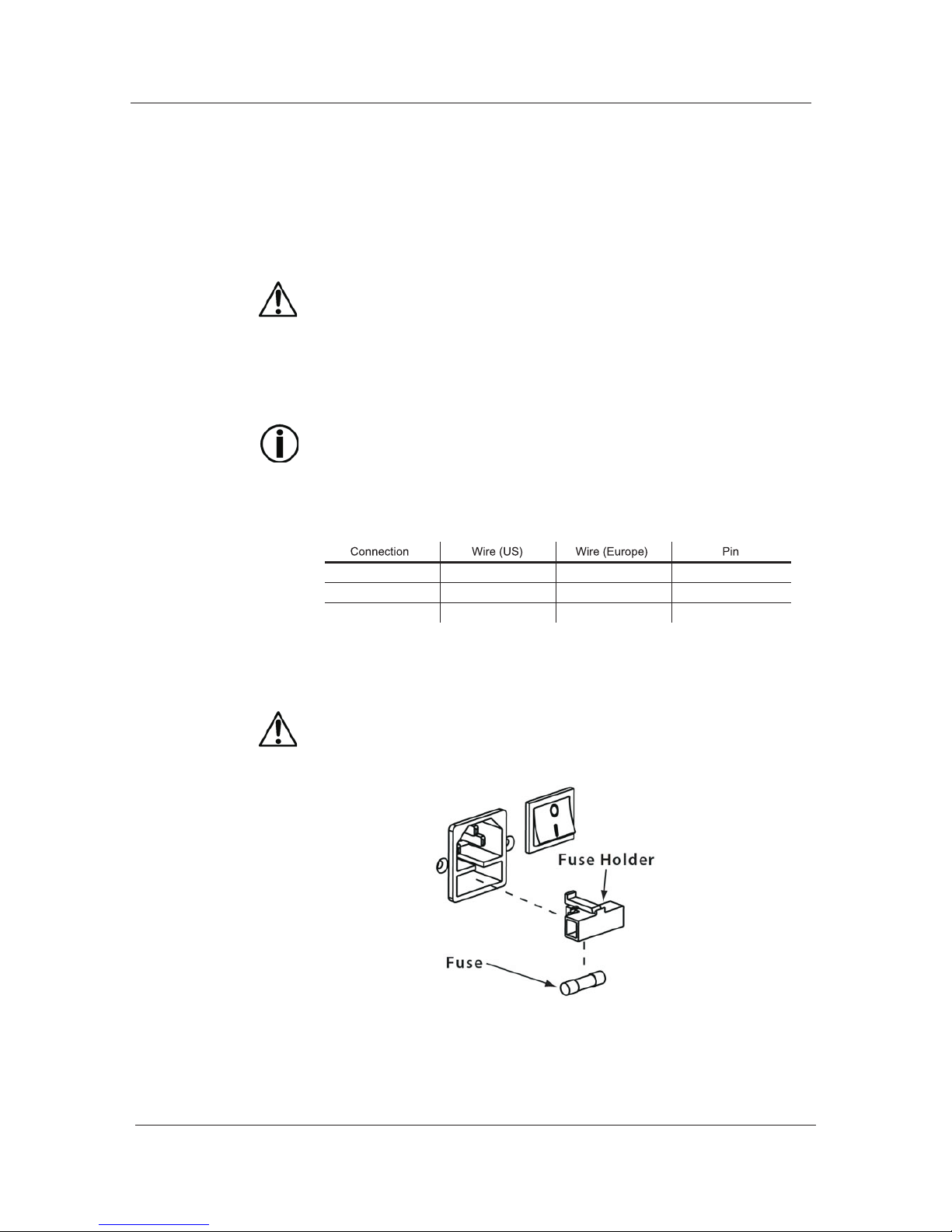
AC Plug ...............................................................................................................................5
Fuse Replacement................................................................................................................5
Gobo Replacement ................................................................................................................6
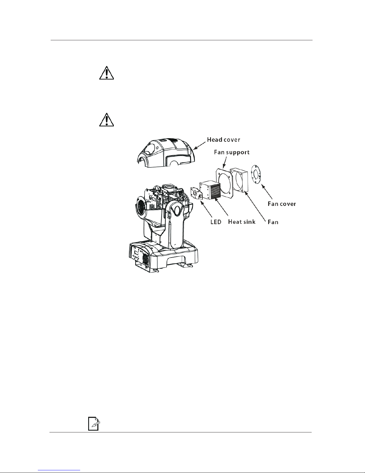
LED Replacement...................................................................................................................6
DMX Linking .........................................................................................................................6
DMX Modes ........................................................................................................................6
Master/Slave Linking .............................................................................................................6
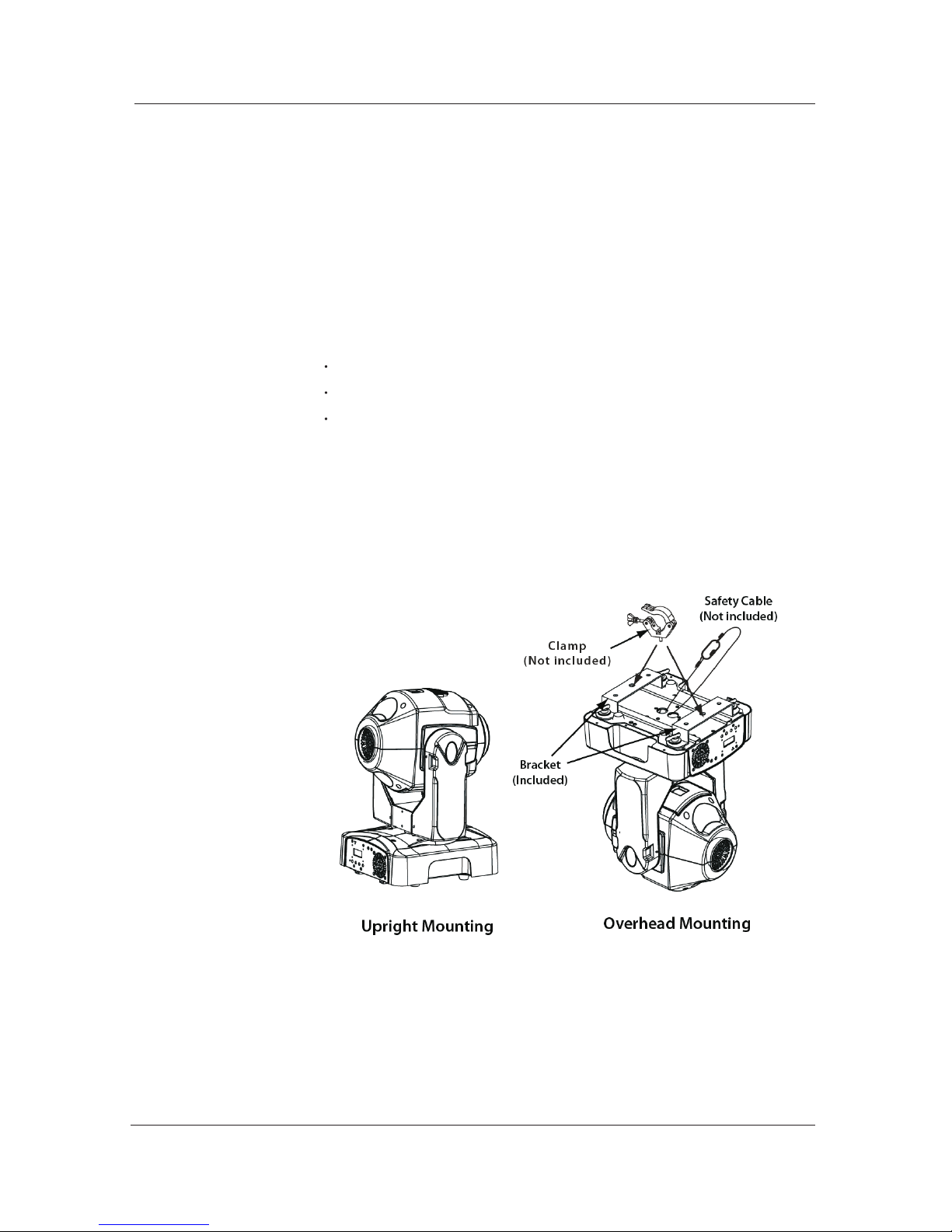
Mounting .............................................................................................................................. 7
Orientation .........................................................................................................................7
Rigging ...............................................................................................................................7
4. Operation .................................................................................................8
Control Panel Description ......................................................................................................8
Control Options .................................................................................................................... 8
Programming ........................................................................................................................8
DMX Operation ..................................................................................................................8
Stand-alone Operation........................................................................................................8
Master/Slave Operation ......................................................................................................8
Display Mode .....................................................................................................................8
Software Version ................................................................................................................8
Keylock .............................................................................................................................9
Movement Inversion ...........................................................................................................9
Color Wheel Movement .......................................................................................................9
Edit Custom .......................................................................................................................9
Range Limitation.................................................................................................................10
Move-in Black .....................................................................................................................10
Reset Control.....................................................................................................................10
System Default ...................................................................................................................10
Menu Map ......................... ....... ...... ....................................................................................11
DMX Values ..........................................................................................................................12
ADVANCED........................................................................................................................12
ADVANCED (Cont.) ............................................................................................................13
BASIC ...............................................................................................................................13
BASIC (Cont.) ....................................................................................................................14
5. Technical Information...............................................................................15
General Maintenance ..................................................................................................................15
Troubleshooting Guide........... ...... ...... ...... .................................................................................16
Exploded View .............................................................................................................................17
Tableof Contents

Parts List .............................................................................................................................18
Photometrics ........................................................................................................................18
Returns Procedure ...............................................................................................................19
Claims .................................................................................................................................19
Technical Specifications........................................................................................................ 20
6. Appendix................................................................................................... 21
DMX Primer ......................................................................................................................... 21
The Physical Medium............................................................................................................ 21
The Signals ......................................................................................................................... 21
The Functions ......................................................................................................................21
DMX Configuration ................................................................................................................21
Personalities ....................................................................................................................... 21
Starting Address .................................................................................................................. 21
Assigning Addresses ............................................................................................................22
DMX Universes ....................................................................................................................22
DMX Connectivity .................................................................................................................22
Fixture Location ...................................................................................................................22
Number of Fixtures ............................................................................................................... 22
DMX Data Cabling ................................................................................................................ 22
Making your Own DMX Cable................................................................................................. 22
DMX Cable Characteristics ....................................................................................................22
DMX Cable Connectors ........................................................................................................ 23
3-Pin to 5-Pin Conversion Chart ............................................................................................ 23
DMX Connection.................................................................................................................. 23
Master/Slave Linking ............................................................................................................. 24
Master/Slave Connection .....................................................................................................24
ID Addressing .......................................................................................................................25
Single Row Connection......................................................................................................... 25
Standard Block Connection .................................................................................................. 25
Repeated Row Block Connection .......................................................................................... 25
Other Effects .......................................................................................................................25
Sizing the Circuit Breakers .....................................................................................................26
Using the Spec Sticker..........................................................................................................26
Using the Watts/Volts Method................................................................................................ 26
Considering the Power Factor ............................................................................................... 26
Using the Volt Amps Method ..................................................................................................26
Selecting the Circuit Breaker ................................................................................................ 26

1. Before you Begin
What is
Included
Unpacking
Instructions
Text
Conventions
Convention Meaning
1~512
50/60
[10]
Claims
<SET>
Settings
MENU > Settings
[1~10]
Yes/No
ON
“COLORado™ UM ™”
A rangeof values
A setof mutually exclusivevalues in thetext
A DIPswitch to beconfigured
A fixturefunction, a newterm, a sectionor a chapter
The name ofanother publication ormanual
A buttonto be pressedon the fixture'scontrol pan
A menuoption that canbe selected butnot modified
A sequenceof menu optionsto be followed
A rangeof menu valuesof which onecan be selected
A setof mutually exclusivemenu options tochoose
A valueto be entered
Icons Icons Meaning
The te rm“ DMX” usedthroughout t hisdocument refers to the USITTD MX512-A
transmission protocol
• One LEDMoving head Light
• One powercord with plug
• Two mounting brackets
• Quick ReferenceGuide
This icon indicatesuseful, although non-criticalinformation.
This icon indicatesimportant installation orconfiguration in
formation. Failure tocomply with thisinformation may prevent
the fixture fromfunctioning correctly.
This icon indicatescritical installation, configuration or operation
information. Failure tocomply with thisinformation may render
the fixture partiallyor completely inoperative,damage third-
party equipment, orcause harm tothe user.
Immediately upon receivinga fixture, carefullyunpack the box. Check the box contents
to ensure thatall parts arepresent and thatthey are in good condition. If any part
appears damaged fromshipping, or ifthe box showssigns of mishandling, notify the
shipper immediately. In addition,retain the boxand all thepacking material for
inspection.
In any event,save the cartonand all packingmaterial because, in case that youhave
to return thefixture to thefactory, you will haveto do soin its original box, with its
original packing. Seethe Claims sectionin the Technical Information chapter.
--1--

Safety
Notes
Operation
Expected LED
Lifespan
Please read the following notes carefully because they include important
safety information aboutthe installation, usageand maintenance ofthis product.
It is importantto read allthese notes beforestarting to workwith this product.
There are nouser serviceable partsinside the light.Any referenceto servicing thisunit
you may findfrom now onin this UserManual will onlyapply to properlyC we certified
technicians. Do noto pen thehousing or attemptany repairs unlessyou are oneof them.
Please refer toall applicable localcodes and regulationsfor proper installation
of the light.
Keep this manualfor future consultation.If you sellthe light toanother user,make
sure that theyalso receive thismanual.
Personal
Safety
Mounting
and Rigging
Power
and Wiring
Avoid direct eye exposureto the lightsource while thefixture is on.
Always disconnectthe light fromits power sourcebefore servicing.
Always connectthe light toa grounded circuitto avoid therisk of electrocution.
This product is for indooruse only! Toprevent risk offire or shock,do not expose
this product torain or moisture.
Make sure thereare no flammablematerials close tothe fixture(s) whileoperating.
When hanging thisfixture, always secureit to afastening device usinga safety
cable (not provided).
Always makesure that youare connecting thelight to the propervoltage, as perthe
specifications in thismanual or onthe product's sticker.
Never connect thelight to adimmer pack.
Make sure thatthe power cableis not cracked,crimped or damaged.
Never disconnect thefixture by pullingor tugging onthe power cable.
The maximum ambient temperature (Ta) is 104 F (40 C). Do notoperate the
fixture at ahigher temperature.
In case ofa serious operatingproblem, stop usingthis product immediately!
In t heunlikely e ventt hat yourlight may requireser vice, pleasecontact our Technical
Support.
LEDs gradually declinein brightness overtime, mostly becauseof heat. Packagedin
clusters, LEDs exhibithigher operating temperaturesthan in idealor singular optimum
conditions. For thisreason, using allcolor .LEDs attheir fullest intensitysignificantly
reduces the LEDs'lifespan. Under normalconditions, this lifespancan be of40,000 to
50,000 hours. Ifextending this lifespanexpectancy is vital,lower the operational
temperature by improvingventilation and reducingthe external temperature, as well
as limiting theoverall projection intensity
--2--

DMX Channel Summary
Function
Pan 1 Pan
Pan Fine 2 Tilt
Tilt 3Color Wheel
Tilt Fine 4Fixed Gobo Wheel (#1)
Pan / Tilt Speed 5 Rotating Gobo Wheel (#2)
Color Wheel 6 Gobo Rotation
Fixed Gobo Wheel (#1) 7 Rotating Prism
Rotating Gobo Wheel (#2) 8 Focus
Gobo Rotation 9 Dimmer
Rotating Prism 10 Strobe
Focus 11 Control
Dimmer
Strobe
Control
--3--

Product Dimensions Drawing Here
Base Fan
Fuse Holder
Control Panel Base Fan
DMX Out
DMX In
Power Input On/Off Switch
--4--

3. Setup
AC Power The light has an auto-ranging power supply that can work with an input voltage range
of 100~240 VAC, 50/60 Hz.
Make sure thatyou are connectingthis product tothe proper voltage,as per the
specifications in thisguide, the product'suser manual oron the product'ssticker.
AC Plug
AC Live Black Brown 1
AC Neutral White Blue 2
3
Fuse Replacement
Always connect thelight to aprotected circuit withan appropriate
electrical ground toavoid the riskof electrocution orfire.
Todetermine the powerrequirements for thelight see thelabel affixed to the sideof
the fixture.Alternatively, you may referto the technicalspecifications chart inthe
TechnicalInformation chapter ofthis manual.
The listed currentrating indicates themaximum current drawduring normal operation.
Please refer tothe Sizing theCircuit B reakerssection in theAppendix chapterof this
manual.
Never c onnectthe light toa r heostat( variable resistor) or dimmercircuit,
even if therheostat or dimmerchannel serves onlyas a 0to 100% switch.
The light comeswith a powerinput cord terminatedwith an IECconnector on oneend
an Edison plugon the otherend (US market).If the powercord that camewith your fixture
has no plugor you needto change theEdison plug, usethe tablebelow to wire thenew plug
AC Ground Green/Yellow Green/Yellow
1) With aflat head screwdriver, wedge thefuse holder outof its housingand remove
the blown fusefrom the holder.
2) Replace theblown fuse witha fuse ofthe exact sametype and rating.
3) Insert thefuse holder backin its place,and reconnect power.
Make sure todisconnect the fixture'spower cord beforereplacing a blownfuse,
and always replaceit with afuse of thesame type andrating.
--5--

Gobo
Replacement
LED
Replacement
1) Unlock thegobo cover andslide it away.
2) Take the targetgobo out ofthe gobo wheel.
3) Install thenew rotating gobo.
4) Slide andlock the gobocover.
Make sure todisconnect the fixture'spower cord beforereplacing the gobo.
1) Remove thehead cover byloosening its screws.
2) Remove thefan cover,the head fan,the fan supportand the heatsink in thisorder.
3) Disconnect andremove the LED.
Mount and connectthe new LED.
5) Reverse steps"2" and "1".
Make sure todisconnect the fixture'spower cord beforereplacing the LED.
DMX Linking
DMX Modes
Master/Slave
Linking
Youmay link thelight to aDMX controller usinga standard DMXserial connection. Ifusing
other DMX compatiblefixtures with thelight, it ispossible to controlthem individually witha
single DMX controller.
It is alsopossible to runseveral DMX compatiblefixtures synchronized withouta DMX
controller in amaster/slave operating mode.
If you arenot familiar withthe DMX standard,please refer tothe DMX Primerand
DMX Connectivity sectionsin theAppendix chapter ofthis manual.
The light usesthe standard DMXdata connection forits DMX modes,Advanced and
Basic. Refer tothe Operation Instructionschapter to learnhow to configurethe light
to work inthese modes. The DMX Values section willgive you detailedinformation
regarding the above-mentionedDMX modes.
The Master/Slave modeallows a fixture(the master) runninga preconfigured
program to controlseveral other fixtures(the slaves) withoutrequiring a DMX
controller. Inthis mode, allthe slave fixtureswill operate in
unison with themaster fixture.
When in Master/Slavemode, the unitslink to eachother using thestandard DMX
connection.
If you arenot familiar withthe Master/Slave connectivity, please referto the DMX
Primer and DMXConnectivity sections inthe Appendixchapter of thismanual.
The Operation chapterof this manualprovides detailed instructionson how to
configure the Masterand Slave units.
--6--

Mounting
Orientation
Rigging
Procedure
Product
Mounting
Diagram
Read the safetynotes at thebeginning of thisguide and followtheir recommendations
before mounting thisproduct.
Always mount thisfixture in anysafe position whilemaking sure thatthere is adequate
room around itfor ventilation.
Make sure tomount this fixtureaway from anyflammable material asindicated in the
Safety Notes.
We recommends following the generalguidelines below whenmounting the light.
When selecting aninstallation location, considerease of accessto the fixturefor
operation, programming adjustmentsand routine maintenance.
Never mount thefixture in placeswhere rain, highhumidity, extreme temperature
changes or restrictedventilationmay affect it.
Make sure thatthe location whereyou are mountingthe fixture cansupport its
weight. Please seethe Technical Specifications sectionof this manualfor the
weight requirement ofthis fixture.
The light comeswith two mountingbrackets to whichyou can attach"C" or
"O" clamps. Youmust supply yourown "C" or"O" clamps andmake sure thatthey are
capable of supportingthe weight ofthis fixture. Youwill have touse two mounting
points per fixture.In addition, youmay mount thisproduct on thefloor or aplatform,
provided it isstable and itcan support theweight of thefixtures on it.
--7--

Exits from thecurrent menu or
function
current
Enables the currently displayed
menu or sets the currently
selected value in to the
function
menu list and increases the
Navigates upwards through the
numeric value when in a function
Navigates downwards through
the menu list and decreases the
numeric value when in a function
Control Options
Programming
DMX Operation
Stand-alone
Operation
Master/Slave
Operation
Youcan set thelight start addressin the 001~512DMX range. This allows for
the control ofup to 36fixtures in the14-channel ADVANCED DMX modeand up
to 46 fixturesin the 11-channel BASIC DMXmode. The Q-Spot 260 LEDdoes not
support IDAddressing.
Carry out allthe programming proceduresindicated below fromthe control panel.
Refer to theMenu Map pageto learn howthe menu optionsrelate to eachother.
Use <ENTER> and<MENU> to changelevels in theMenu M ap.This is equivalent
to move rightand left respectively. Use <UP>and <DOWN> tomove vertically
within theMenu Mapoptions.
1) Select DMXoperation
a) Go toMENU > INTRO> RUN
b) Select DMX512
2) Select aDMX mode
a) Go toMENU > INTRO> CHANNELS
b) Select BASICor ADVANCED
3) Select thestarting address
a) Go toMENU > INTRO> ADDRESS
b) Select astarting address, 001~ 498 (Advanced)or 001~501 (Basic)
1) Go toMENU > INTRO> RUN
2) Select astand-alone operation mode(AUTO 1, AUTO 2, SOUND 1,SOUND 2,
CUSTOM or TEST)
1)Configure the Masterfixture
a) Select astand-alone mode, asindicated above
2)Configure the Slavefixtures
a) Go toMENU > INTRO> RUN
b) Select SLAVE
Of all thest and-alone operationmodes i ndicatedab ove, only " CUSTOM" is
editable (see EditCustom).
1) Go toMENU > INTRO> DISPLAY
2) Select adisplay mode (60CLOSE or BRIGHT)
When in the"60 CLOSE" setting,the display backlightwill turn off after 60s.
When in the"BRIGHT" setting, thedisplay backlight willstay on.
1)Go to MENU> INTRO >INFO
2)The display willshow the installedsoftware version.
--8--

Keylock
Movement Inversion
Color Wheel
Movement
Edit Custom
1) Go toMENU > INTRO> KEYLOCK
2) Select YES or NO
When i nt he "YES" set ting, the user will have to enter t hepassword after 30
seconds of controlpanel inactivity oreach time he/sheturns the fixtureon.
The default (non-modifiable)password is <UP>, <DOWN>, <UP>, < DOWN>and
<ENTER>.
1) Go toMENU > INVERT > PAN
2) Select amovement mode (NORMALor REVERSE)
3) Go toMENU > INVERT > TILT
4) Select amovement mode (NORMALor REVERSE)
5) Go toMENU > INVERT > USE
6) Select YES to activatethe new settingsor NO tostop using them.
1) Go toMENU > INVERT > COLOR
2) Select amovement mode (STEPor LINEAR)
3) Go toMENU > INVERT > USE
4) Select YES to activatethe new settingor NO tostop using it.
1)Go to MENU> EDIT > STEP
2) Select aprogramming step (000~255)
3) Go toMENU > EDIT> PAN
4) Select apan value (000~255)
5) Go toMENU > EDIT> TILT
6) Select atilt value (000~255)
7) Go toMENU > EDIT> XY SPEED
8) Select atilt/pan movement speed(000~255)
9) Go toMENU > EDIT> COLOR
10) Select acolor wheel position(000~255) as perthe DMX Values table
11) Go to MENU> EDIT > GOBO 1
12) Select afixed gobo (000~255)as per theDMX Values table
13) Go toMENU > EDIT> GOBO 2
14) Select arotating gobo (000~255)as per theDMX Values table
15) Go toMENU > EDIT> GOBO 2ROT
16) Select arotating gobo mode(000~255) as perthe DMX Values table
15) Go toMENU > EDIT> PRISM
16) Select arotating prism mode(000~255) as perthe DMX Values table
17) Go toMENU > EDIT> FOCUS
18) Select afocus position (000~255)
19) Go toMENU > EDIT> DIMMER
20) Select adimmer setting (000~255)
21) Go toMENU > EDIT> STROBE
22) Select astrobe setting (000~255)as per theDMX Values table
23) Go toMENU > EDIT> TIME
24) Select theduration of thisstep (000~255)
25) Go toMENU > EDIT> USE
26) Select YES to savethe settings forthis step orNO to deletethem.
27) Repeat steps"3" to "26"for the othersteps
To r epeat theCustom s tepsin a ne ndless loopmode, c onfigure the " TIME"
setting of thelast step as"0".
--9--

Range Limitation
Move-in Black
Reset Control
System Default
1)Go to MENU> RANGE >P/START
2)Select the startingpoint for thelimited pan (000~255)
3)Go to MENU> RANGE >P/FINISH
4)Select the finishingpoint for thelimited pan (000~255)
5)Go to MENU> RANGE >T/START
6)Select the startingpoint for thelimited tilt (000~255)
7)Go to MENU> RANGE >T/FINISH
8)Select the finishingpoint for thelimited tilt (000~255)
9)Go to MENU> RANGE >USE
10)Select YES to activate thenew settings orNO to stopusing them.
1) Go toMENU > SPECIAL> BLACK
2) Select YES to enablethe 3 secondsdelay or NOto make theblackout immediate.
1)Go to MENU> SPECIAL> RESET
2)Select DMX toenable the DMXcontroller to resetthe fixture (Controlfunction) or
NO to resetthe fixture onlyfrom the controlpanel.
1)Go to MENU> DEFAULT > DEFAULT
2)Select YES to default thefixture to itsoriginal factory settings.
--10--

--11--

ADVANCED Channel Function
000 255 0~540°
000 255 Fine movement control
000 255 0~270°
000 255 Fine movement control
000 255 Fast~Slow
000 016
017 033
034 050
051 067
068 084
085 101
102 118
119 135
136 152
153 255
White
Red
Yellow
Magenta
Green
Orange
Blue
Light blue
Light green
Rainbow or linear effect
000 009
010 019
020 029
030 039
040 049
050 059
060 069
070 079
080 089
090 099
100 114
115 129
130 144
145 159
160 174
175 189
190 204
205 219
220 234
235 255
No gobo
Gobo 1
Gobo 2
Gobo 3
Gobo 4
Gobo 5
Gobo 6
Gobo 7
Gobo 8
Gobo 9
Shaking gobo 9
Shaking gobo 8
Shaking gobo 7
Shaking gobo 6
Shaking gobo 5
Shaking gobo 4
Shaking gobo 3
Shaking gobo 2
Shaking gobo 1
Flow effect
000 009
010 019
020 029
030 039
040 049
050 059
060 069
070 079
080 099
100 119
120 139
140 159
160 179
180 199
200 219
220 255
No gobo
Gobo 1
Gobo 2
Gobo 3
Gobo 4
Gobo 5
Gobo 6
Gobo 7
Shaking gobo 7
Shaking gobo 6
Shaking gobo 5
Shaking gobo 4
Shaking gobo 3
Shaking gobo 2
Shaking gobo 1
Flow effect
000 060
061 158
159 255
Gobo indexing
CW rotation (Slow~Fast)
CCW rotation (Slow~Fast)
000
001 004
005 127
128 132
133 255
No function
Prism engaged (no rotation)
CCW rotation (Slow~Fast
No function
CW rotation (Slow~Fast)
000 255
000 255 Dark~Bright
(Continues on next page)
....
....
....
....
....
....
....
....
....
....
....
....
....
....
....
....
....
....
....
....
....
....
....
....
....
....
....
....
....
....
....
....
....
....
....
....
....
....
....
....
....
....
....
....
....
....
....
....
....
....
....
....
....
....
....
....
....
....
....
....
--12--

ADVANCEDADVANCED
000-----031
032-----063
064-----095
096-----127
128-----159
160-----191
192-----223
224 255
Close
Open
Strobe (Slow~Fast)
Open
Pulse strobe effect (Slow~Fast)
Open
Random strobe effect (Slow~Fast)
Open
000-----
01
9
020-----039
040-----059
060-----079
080-----099
100-----119
120-----139
140-----159
160-----179
180-----199
200-----219
220-----255
No function
Pan/tilt black activation (3 s delay)
Pan/tilt black deactivation (3 s delay)
Auto 1 (3 s delay)
Auto 2 (3 s delay)
Sound 1(3 s delay)
Sound 2(3 s delay)
Custom
Test (3 s delay)
No function
Reset (3 s delay)
No function
000-----255 0~540°
000-----255 0~270°
000-----016
017-----033
034-----050
051-----067
068-----084
085-----101
102-----118
119-----135
136-----152
153-----255
White
Red
Yellow
Magenta
Green
Orange
Blue
Light blue
Light green
Rainbow or linear effect
000-----009
010-----019
020-----029
030-----039
040-----049
050-----059
060-----069
070-----079
080-----089
090-----099
100-----114
115-----129
130-----144
145-----159
160-----174
175-----189
190-----204
205-----219
220-----234
235-----255
No gobo
Gobo 1
Gobo 2
Gobo 3
Gobo 4
Gobo 5
Gobo 6
Gobo 7
Gobo 8
Gobo 9
Shaking gobo 9
Shaking gobo 8
Shaking gobo 7
Shaking gobo 6
Shaking gobo 5
Shaking gobo 4
Shaking gobo 3
Shaking gobo 2
Shaking gobo 1
Flow effect
-----
--13--

000-----009
010-----019
020-----029
030-----039
040-----049
050-----059
060-----069
070-----079
080-----099
100-----119
120-----139
140-----159
160-----179
180-----199
200-----219
220-----255
No gobo
Gobo 1
Gobo 2
Gobo 3
Gobo 4
Gobo 5
Gobo 6
Gobo 7
Shaking gobo 7
Shaking gobo 6
Shaking gobo 5
Shaking gobo 4
Shaking gobo 3
Shaking gobo 2
Shaking gobo 1
Flow effect
000-----060
061-----158
159 255
Gobo indexing
Clockwise rotating from slow to fast
Anti-clockwise rotating from slow to fast
000
001-----004
005-----127
128-----132
133-----255
No function
Prism engaged (no rotation)
CCW rotation (Slow~Fast)
No function
CW rotation (Slow~Fast)
000-----255
000-----255 Dark~Bright
000-----031
032-----063
064-----095
096-----127
128-----159
160-----191
192-----223
224-----255
Close
Open
Strobe: Slow~Fast
Open
Pulse strobe effect: Slow~Fast
Open
Random strobe effect: Slow~Fast
Open
000-----019
020-----039
040-----059
060-----079
080-----099
100-----119
120-----139
140-----159
160-----179
180-----199
200-----219
220-----255
No function
Pan/tilt black activated (activated after 3 s)
Pan/tilt black deactivated (activated after 3 s)
Auto 1 (activated after 3 s)
Auto 2 (activated after 3 s)
Sound 1(activated after 3 s)
Sound 2(activated after 3 s)
Custom
Test (activated after 3 s)
No function
Reset (activated after 3 s)
No function
----
--14--

To clean a fixture, follow the below recommendations:
Always dry the external optics and glass surfaces carefully after cleaning them.
Tomaintain optimum performanceand minimize wear, the usershould clean the light
fixtures frequently. Usage and environment are contributingfactors in determiningthe
cleaning frequency. As a rule, the user should clean the fixtures at least twice a
month. Dust buildup reduces lightoutput performance andcan cause overheating.
This can leadto reduced lightsource life andincreased mechanical wear.
We recommends cleaning the fixture'sexternal optics witha soft clothusing normal
glass cleaning fluid.
Unplug the fixturefrom power.
Wait untilthe fixture iscold.
Use a vacuum(or dry compressedair) and asoft brush toremove dust collectedon
the external ventsand reachable internalcomponents.
Clean all externaloptics and glasssurfaces with amild solution ofglass cleaner or
isopropyl alcohol, anda soft, lintfree cotton clothor a lenscleaning tissue.
Apply thesolution directly tothe cloth ortissue and dragany dirt andgrime to the
outside of thelens.
Gently polish theexternal glass surfacesuntil they arefree of hazeand lint.
When cleaning unitswith a movablemirror, youshould keep thecontact with the
mirror surface toa minimum toavoid scratching ordamaging it.
If the fixture has one or compressedair. refrainfrom spinning themusing
compressed air.
General
Maintenance
--15--

Troubleshooting Guide
Fixture is on
LED is off
LED connection problems Reconnect LED
Faulty LED Replace LED
Faulty LED driver Replace LED driver
Fixture is on
Head fan is off
Faulty head fan Replace head fan
Faulty LED driver Replace LED driver
Fixture is on
Base fan is off
Faulty base fan Replace base fan
Faulty power supply Replace power supply
Color wheel problem
Faulty color wheel motor Replace color wheel motor
Faulty sensor board Replace sensor board
Faulty X/Y control board Replace X/Y control board
Replace X/Y control board
Prism problem
Faulty prism motor Replace prism motor
Faulty prism belt Replace prism belt
Faulty X/Y control board
Gobo wheel problem
Faulty gobo wheel motor Replace gobo wheel motor
Blocked gobo wheel Unblock
Faulty sensor board Replace sensor board
Faulty X/Y control board
Pan movement problem
Faulty pan motor Replace pan motor
Faulty pan belt Replace pan belt
Faulty magnetic sensor Replace magnetic sensor
Faulty optical sensor Replace optical sensor
Faulty X/Y control board
Tilt movement problem
Faulty tilt motor Replace tilt motor
Faulty tilt belt Replace tilt belt
Faulty magnetic sensor Replace magnetic sensor
Faulty optical sensor Replace optical sensor
Faulty X/Y control board
Circuit breaker/fuse keeps
tripping/blowing
Excessive circuit load Check total load placed on the electrical circuit
Short circuit along the power wires
Fixture does not power up
No power Check for power on power outlet
Loose or damaged power cord Check power cord
Blown fuse Replace fuse
Faulty On/Off switch Replace On/Off switch
Faulty internal power supply Replace internal power supply
Fixture does not respond
to DMX
Wrong DMX addressing Check control panel and unit addressing
Damaged DMX cables Check DMX cables
Wrong polarity on the controller Check polarity switch settings on the controller
Loose DMX cables Check cable connections
Faulty DMX interface
Faulty Display board
DMX signal problems
Non DMX cables Use only DMX compatible cables
Bouncing signals Install terminator as suggested
Long cable / low level signal Install an opticallycoupled DMX splitterright after
the fixture withthe strong signal
Too many fixtures Install an optically coupled DMX splitter after unit
#32 or before
Interference from AC wires Keep DMX cables separated from power cables or
fluorescent/black lights
If you stillex perience technical problems after tr yingthe a boves olutions, contact
our Technical Support.
Check for ashort in theelectrical wiring
Replace X/Y control board
Replace the displayboard
--16--

Exploded View
--17--
Table of contents
Other ViSAGE Light Fixture manuals
Popular Light Fixture manuals by other brands

Balluff
Balluff BNI IOL-800-000-Z036 user guide

Ortech
Ortech OE-G026 instruction manual

Blizzard Lighting
Blizzard Lighting Wink manual

Sunleaves
Sunleaves Sunspot 6 Plug N’ Play instructions

Quasar Science
Quasar Science Q-Lion quick start guide

Schrack Technik
Schrack Technik ILAS LED Series Assembly instructions

BlissLights
BlissLights BlissEmber user guide

Flash
Flash F7100299 user manual

Beamz
Beamz MHL-1410Wispot14x 10W Quad DMX 2.4Ghz manual

Sagitter
Sagitter ARCHERB1 user manual

Anolis
Anolis ArcSource Outdoor 24 MC Integral SmartWhite User instructions

LumaPro
LumaPro 2ZB95A Operating instructions and parts manual