VISICO Speedlite VS-765 User manual

Speedlite
User Manual
VS-765
For Nikon

Introduction
Thank you very much for selecting VS-765
Speedlite. Please read instruction carefully
and keep them handy for your reference.
VS-765 Speedlite is a combination of world's
first-class electronic technology and excellent
manufacturing. It equips with multiple
advanced and practical features as follows.
We hope its durable performance and
beautiful light will bring you with productive
shooting experience.
GN58@ISO100, 105mm
Support TTL, M manual, Multi flash
Support high speed sync, first curtain sync,
and second curtain sync.
2.4GHz Frequency, 25m effective trigger
4 independent transmission channels, 3
groups (A,B,C)
Enable to use as Master flash and Slave flash
Power range from 1/1 to 1/128 power
5500k±200K color temperature
Zoom head can reach from 24-105mm
AF-Assist beam
Automatic power off function
USB port for firmware upgrades
01
·
·
·
·
·
·
·
·
·
·
·
·

Description
Safety Note………………………………………
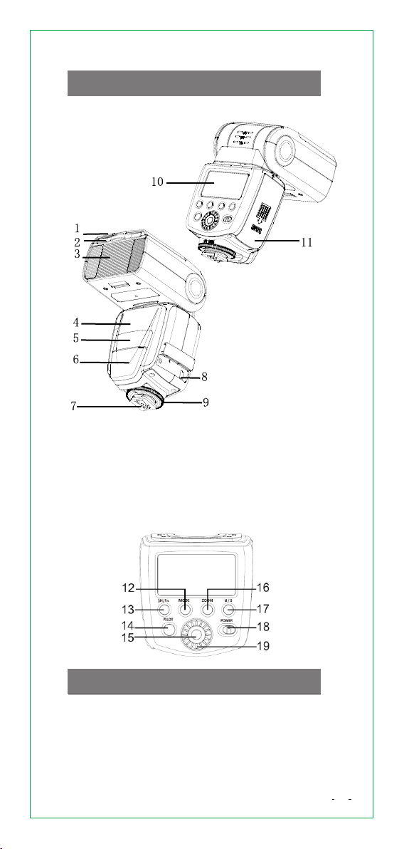
Name of Parts……………………………………
Button Operation………………………………
LCD Panel…………………………………………
Install Battery……………………………………
Attach Speedlite…………………………………
Turn on the Power………………………………
Flash Mode - ITTL Auto Flash…………………
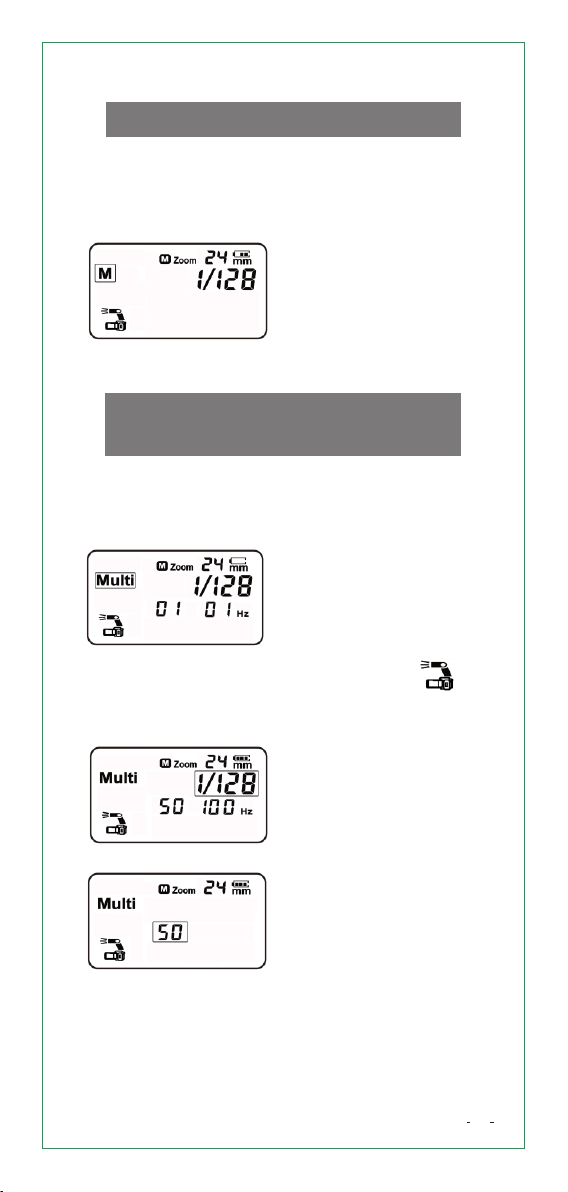
Flash Mode - M Manual Flash…………………
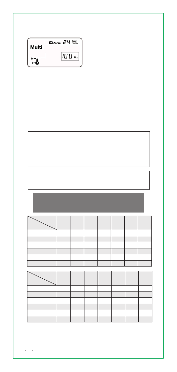
Flash Mode - Multi Stroboscopic Flash………
High-speed Sync ………………………………
Second-curtain Sync……………………………
S1 and S2 Optical Mode………………………
Wireless Flash Shooting………………………
Set Master Unit and Slave Unit ………………
Three Kinds of Master Control Modes ………
Slave Mode………………………………………
Set Transmission channel and Group
on Slave Unit……………………………………
Select Transmission channel and Group
on Master Unit……………………………………
Master Unit Sets Different Flash Mode
for Every Group of Slave Units………………
AF-assist Light………………………………
Bounce Flash……………………………………
Catchlight Panel…………………………………
Zoom: Flash Coverage Setting………………
Wide Panel………………………………………
Setting Custom Functions………………………
Reset Factory defaults…………………………
Overheating Protection…………………………
Specifications……………………………………
Firmware Update………………………………
Maintenance……………………………………
Troubleshooting…………………………………
02
.
3
4
4
5
6
6
6
7
8
8
10
11
11
12
12
12
13
13
14
14
16
16
17
17
18
18
19
19
19
21
21
21

Do not expose to rain or become damp.
Do not get the unit close to hot objects.
Do not use the unit in an environment where
flammable vapor is likely to come in contact
with the unit.
Do not use a flash with damaged covers.
Do not attempt to disassemble or service
the unit on your own to avoid shock hazard.
Do not use flash close to the eyes.
Always keep out of reach of children.
Remove battery before long-term non-use
of the flash.
SafetyNote
03
◆
◆
◆
◆
◆
◆
◆
◆

NameofParts
1. Catchlight Panel
2. Wide Panel
3. Flash Head
4. Wireless Trigger Sensor
5. Slave flash Ready
Indicator
6. AF-assist Light
7. Hot Shoe
8. USB Upgrade Terminal
9. Locking Screw
10. LCD Screen
11. Battery Cover
04
12. Flash Mode Selection /
Transmission channel and
Group Setup Button
13. Sync Mode Selection/
Custom Functions Setup
Button
14. Test Button
15. Confirm Button
16. Zoom Selection
Button
17. Master/Slave Unit
Selection Button
18. Power Switch
19. Select Dial
Button Operation

LCDPanel
1. <ITTL> Auto flash
2. Manual zoom mode
3. Lens focal length
4. Battery power display
5. <M> manual flash/ <Multi>
stroboscopic Flash
6. High speed sync
7. Second curtain sync
8. Wireless flash mode
9. S1/S2 Optical slave flash
10. 2.4G wireless single
transmission
11. Transmission channel
12. Group
13. Flash output power/
Flash exposure
compensation
14. Flash frequency/ Number
of flashes
Master unit flash ON
Master unit flash OFF
Exit master unit flash
05
Slave unit

Fig.1 Fig.2
Push the [Battery Cover] downward, and
open the battery cover.
According to “+” and “-” indicator on the
battery compartment, install 4 pieces of
AA batteries
Slide [Battery Cover] upward and locks the battery.
Caution: Please use regular AA batteries.
After a sequence of continuous shots, be aware
that the battery might be hot.
When replace batteries, please use 4 pieces of
new batteries from the same brand.
If the unit is not used for a long time, please turn
off Speedlite and remove battery.
Installbattery
Slip the Speedlite's mounting foot all the way
into the camera's hot shoe.
Rotate locking ring clockwise to attach the
Speedlite on camera firmly.
Rotate locking ring anticlockwise to detach the
Speedlite.
AttachSpeedlite
TurnonthePower
Switch [POWER] button to right side to turn
on the unit. Flash-ready lamp turns to red
(fully charged), press [PILOT] button to fire a
test flash.
When set as a MASTER flash, the power will
turn off automatically after approx. 90 seconds
battery not include
06

FlashMode-ITTLAutoFlash
In ITTL mode, flash-metering system of the camera
determines the accurate flash exposure for the
subject and the background.
Press [MODE] button and
set to <ITTL>.
Press camera shutter
halfway to focus. The
shutter speed and
aperture are displayed
in the viewfinder.
Press camera shutter
completely, the flash
will fire and the picture
will be taken.
1)SetSpeedlitein
ITTLMode
·
·
·
2)SetFlashExposure
Compensation
The FEC range is
adjustable from -3.0
to +3.0 in precision
1/3 f-stop increments.
FEC is very useful to make
quick minor adjustment of
exposure of the TTL
system, and create ideal
exposure as you like.
·
07
of idle use. To wake up the Speedlite again,press
camera shutter halfway or press any flash button.
When set as a slave flash, it will go to sleep mode
after approx. 60 minutes of idle use.
To wake up the Speedlite again, press any flash
button.
When use as off-Speedlite, disabling “Auto
Power Off” is recommended. (Set Fn 01 to <oF>)
Turn [Select Dial] to adjust
FEC value. “+” means more
exposure. “-“ means less
exposure. Cancel the flash
exposure compensation,
set the amount to “0.0”.
·
When FEC is +3.0, if still underexposure,
please adjust setting on your camera in terms
of shutter speed, aperture, ISO, etc.

08
1) Set flash mode <M>
Press [MODE] button and
set to <M> .
2) Set flash output
power
Turn [Select Dial] to
choose a desired flash
output power.
FlashMode-MultiStroboscopic
Flash
According to one shutter signal, the flash will
generate a series of fast flashes, and multiply images
will be integrated in one picture. It is useful to capture
trajectory of a moving object.
FlashMode-Mmanualflash
When use flash in manual mode, flash output power
is adjustable from 1/1 to 1/128 (8 f-stops) in 1/3 f-stop
increment. To obtain a correct flash exposure, use
a hand-held flash meter to determine the required
flash output.
1) SetFlashMode
<Multi>
Press and hold [M/S] button
for 3 seconds and set to
master unit mode.
Repeatedly press [M/S]
button and set to < >
Press [MODE] button,
and set to <Multi>
2)SetFlashOutput
Turn [Select Dial] to set a
desired flash output power.
Flash output power is
variable from 1/4 to 1/128.
3)S etnumberof
flashes
Press and hold [Confirm
Button] for 3 seconds and
set to <number of flashes>.
Turn [Select Dial] to choose
desired number of flashes
(1-50).

4)Setflashfrequency
Press and hold [Confirm
Button] for 3 seconds and
set to <number of flashes>.
Press [Confirm Button] and
set to <flash frequency>.
Turn [Select Dial] to choose
desired frequency(1-100).
Caution: To prevent flash damage from
overheating, don't continuously use stroboscopic
flashes more than 10 times. After 10 times, please
rest flash at least 15 minutes. If overheating
protection is active, flash will stop firing, please
cool down flash for at least 15 minutes.
Use stroboscopic flash in a dark environment is
more effective.Maximum output power of
stroboscopic flash is 1/4.
09
To ensure shooting effect,you may use the formula
below to calculate the shutter speed and set it with
the camera.Shutter Speed=Number of Flashes /
Flash Frequency For example, when the display
shows 15 Multi and 10Hz, the shutter speed 15/10=
is 1.5s.
MaximumNumberof
ContinuousFlashes
Flash
output
HZ 1 2 3 4 5 6-7 8-9
1/47 6 5 4 4 3 3
1/8
1/16
1/32
1/64
1/128
14 14 12 10 8 6 5
30 30 30 20 20 20 10
50
50
50
50
50
50
50
50
50
50
50
50
50
50
50
40
50
50
30
50
50
HZ 10 12 14 16 18 20-50 60-100
1/42 2 2 2 2 2 2
1/8
1/16
1/32
1/64
1/128
444 4 4 4 4
8 8 8 8 8 8 8
20 20 20 18 16 12 10
50 40 40 35 30 20 15
50 50 50 50 40 40 30
Flash
output

High-speedSync
With high-speed sync, the flash can synchronize
with shutter speed up to 1/8000s . When
photographers shoot portraits in bright sun with
wide open aperture, fast shutter speed can cut the
ambient light, get amazing result as you want.
SetHigh-SpeedSync
When using it as a master
unit, repeatedly press
[ H/Fn] button to display
< >.
Check if the high-speed
sync symbol < > is lit
in the viewfinder.
When using it as a slave
unit, the symbol < > is
not displayed, but it
automatically matches
the high-speed sync.
10
·If you set shutter speed equal to or slower than
the camera's maximum flash sync speed, < >
will not be displayed in the viewfinder.
·The faster the shutter speed, the shorter the
effective flash range.
·Multi flash can't be used under high-speed sync
mode.
·Overheating protection may be active after 15
successive high-speed sync flashes. Please turn
off the flash and rest it for a while to cool down.
·
·
·
ChooseAUTOFPoncameratouse
highspeedsync
Only when shutter sync speed on Nikon camera
is set to “1/250 (AUTO FP)” or “AUTO FP”, high
speed sync of transmitter will be effective.
Please refer to following steps to realize “high
speed sync”.
1. Slip the speedlite's mounting foot fully into the
camera's hot shoe. Rotate locking ring clockwise,
to attach speedlite on camera firmly.
2. Turn on Camera. Choose P/Tv/Av/M/B mode by
turning the mode dial.
3. Press the [MENU] button on camera, choose
[CUSTOM SETTING MUEU], and select
[Bracketing/flash].

4. Select [Flash sync speed]
5. Select Flash sync speed 1/250 (AUTO FP) or turn
on [Auto FP] .
The setting screen varies depending on the camera.
Second-curtainSync
Shooting with slow shutter speed and second-curtain
sync, you can capture a trajectory of moving light.
The flash fires right before shutter closes.
SetSecond-curtain
Sync
·
When the flash is used as
a master unit, repeatedly
press [ H/Fn] button to
display <>.
When the flash is used as
a slave unit, the symbol
<> is not displayed, but
it automatically matches
the second-curtain sync.
·
When the flash is used as a slave unit, in <M> manual
mode, the flash can function as optic S1 and S2
secondary flash with optic sensor.
S1andS2OpticalMode
11

S1 is suitable for manual
flash environment. The
master flash should set at
<M> manual flash mode.
In <S1> mode,the slave
unit will auto flash
immediately when the
master flash fires.
S2 is suitable for TTL flash
environment. The master
flash should set at <TTL>
flash mode. In S2 mode,
the unit will neglect the
pre-flash and only fire in
response to the second
main flash from the master
unit.
Set the camera's shooting mode to P/Tv/
Av/M/B
WirelessFlashShooting
This product supports wireless flash and functions
as either a master or a slave unit. “Master flash”
refers to the flash attached on a camera. “Salve
unit” refers to the one will be controlled by the
master flash. The master flash is able to control two
or three slave groups. Any flash settings in <ITTL>
and <M> mode on master unit will be automatically
transmitted to the slave units. You do not need to
operate the slave unit while shooting.
SetMasterunitandSlaveunit
Press and hold [M/S] button for 3 seconds to switch
between “Master unit” and “Slave unit”.
ThreeKindsofMasterControlModes
When the flash is used as a master unit, please find
three kinds of flash control mode below.
Selectcontrolmodeofmasterunit
Repeatedly press [M/S] button to switch three kinds
of Master control mode.
SetS1/S2
Hold and press [M/S] button for 3 seconds and set
to slave unit mode. Repeatedly press [M/S] button
to choose S1 or S2.
Ⅰ Ⅱ Ⅲ
12

Symbol Meaning
Master unit and slave unit fire at
the same time.
Master unit is set to OFF, only the
slave units will fire a flash.
Slave unit is set to OFF, only the
Master unit will fire a flash.
SlaveMode
When the flash is used as a
slave unit, a symbol will
display on the screen as
shown in the picture.
SetTransmissionchanneland
GrouponSlaveUnit
SetTransmission
channel
1. Press and hold [M/S]
button for 3 seconds and set
to slave mode.
2. Press and hold [MODE]
button for 3 seconds, so that
<CH> is displayed on the
screen.
3. Turn the [Select Dial] to
choose a transmission
channel number from 1 to 4.
4. Press and hold [MODE]
button for 3 seconds or turn
off the power to save
parameter.
SetGroup
1. Press and hold [M/S] button
for 3 seconds and set to
slave mode.
2. Press and hold [MODE]
button for 3 seconds, so that
<CH> is displayed on the
screen.
3. Press and hold [MODE]
button for 3 seconds twice,
so that <GROUP> is
displayed on the screen.
4. Turn the [Select Dial] to
choose Group number from
A to C.
13

SelectTransmissionchanneland
GrouponMasterUnit
SetTransmission
channel
1. Press and hold [M/S]
button for 3 seconds and
set to master mode.
2. Press and hold [MODE]
button for 3 seconds, so
that <CH> is displayed on
the screen.
3. Turn the [Select Dial]
to choose a transmission
channel number from 1 to 4.
4. Press and hold [MODE]
button for 3 seconds or turn
off the power to save
parameter.
SetGroup
1. Press [Confirm Button] to
select group from A to C. The
slave flash selected group
<A> by default. The selected
group will be underlined, and
the screen shows output
power of current selected
group. After you finish all the
settings for group <A>, press
[Confirm Button] will start
the setting for <B>.
2. Turn the [Select Dial] to
choose a desired flash
output.
3. Slave units under the
same group will be
controlled as if they were
one speedlite
MasterUnitSetsDifferentFlash
ModeforEveryGroupofSlave
Units
14

1.Setmasterunitandslaveunit
1.Set one speedlite attached to the camera as the
master unit. Set other speedlites to be controlled
wirelessly as the slave unit.
2.Selectcontrolmodeofmasterunit
Press and hold [M/S] button for 3 seconds and select
“Master unit”. Repeatedly press [M/S] button to
select control mode of master unit (Master unit
and slave unit fire at the same time) or (Master
unit is set to OFF, only the slave units will fire a
flash).
3.Checkthetransmissionchannel
Check the transmission
channel. If the channel of
the master unit and slave
unit(s) are different, set
them to the same
transmission channel number.
5.Setthefiringgroupoftheslaveunit
Operate and set the slave units one by one. Press
[Confirm Button] to select firing group <A>,<B>,<C>.
4.Positionthecameraandtheflash
Position them like above picture.
6.Settheflashmode
Set the flash mode of each firing group by operation
the master unit.Press [Confirm Button] to select the
firing group.
Press [MODE] button repeatedly to select the flash
mode of the selected group from <ITTL>、<M> and
<--> (OFF).
7.Settheflashoutputorflashexposure
compensationamount
While a firing group is selected, turn [Select Dial] to
set the flash function corresponding to the flash
mode.When using the <M> mode, set the flash
output power.When using the <ITTL> mode, set
the flash exposure compensation amount as
required.
15

8.T akethepicture
Press [PILOT] button, each slave unit fires in
the respective flash modes set. If slave units
do not fire a flash, please adjust the angel or
distance between master unit and slave units.
No matter where the slave unit's flash head is
toward, be sure that its wireless sensor faces
the master unit, and make sure the slave unit
is placed in an effective transmission range of
the master unit. Do not put obstacles between
master flash and slave flash.
AF-assistBeam
When autofocus cannot achieve focus on the subject
in low-light or when contrast is low, the build-in AF-
assist beam will actives automatically to help
autofocus.
Position Effecive
Range
Center 0.6~10M
Periphery 0.6~5M
BounceFlash
By pointing the flash head toward a wall or ceiling,
the flash will bounce off the surface before
illuminating the subject. This can soften shadows
behind the subject for a more nature-looking shot.
This is called bounce flash.
To set the bounce direction, hold the flash head and
turn it to a satisfying angle.
16

CatchlightPanel
• If the wall or ceiling is too far away, the bounced
flash might be too weak and result in
underexposure.
•T he wall or ceiling should be plain white for high
reflectance. If the bounce surface is not white, a
color cast may result in the picture.
Using the catchlight panel enables you to reflect
light in a person's eyes and create a more vivid
expression.
3. Push back the [wide
panel]. Shoot using the
same method as bounce
shooting.
1. Turn the flash head
90° up.
2. Pull out the [wide panel].
The [catchlight panel] is
also pulled up at the same
time.
To obtain captivating catchlight in a person's
eyes, shoot within 1.5m of the subject.
Position the flash head towards the front and
90° up. When the flash head is rotate to the
left or right, the catchlight is not very effective.
Zoom:FlashCoverageSetting
The flash coverage can be set automatically or
manually in a range of 24~105mm. Using built-in
wide panel, you can perform flash shooting with
ultra-wide angle lenses up to 14mm.
When the flash is used as a master unit, repeatedly
press [ZOOM] button to select Manual Zoom or Auto
Zoom.
Auto Zoom: <M> doesn't appear on the LCD panel.
The flash coverage is automatically adjusted
according to the focal length of the shooting lens.
Manual Zoom: <M> appears on the LCD panel.
Press [ZOOM] button to change the flash coverage
in sequence (24, 28, 35, 50, 70, 80, 105mm).
17

Auto ZoomManual Zoom
If set flash coverage manually, make sure flash
coverage is wider than the angle of view you are
shooting, to prevent the periphery of the picture
from being dark.
WidePanel
When you use the flash's built-in wide panel, you can
perform flash shooting with ultra-wide angle lenses
up to 14mm.
Pull out the [wide panel].
The [catchlight panel] is
also pulled up at the same
time.
Push back the [catchlight
panel].
SettingCustomFunctions
Custom
Functions No. Function Setting Code Description
Fn01 Auto power
off
ON
OF
Enable
Disable
Fn08
Fn20
Fn22
AF-assist
beam firing
Beep
LCD panel
illuminate
ON
ON
OF
OF
OF
ON
Enable
Enable
OFF
Disable
Disable
ON
12 On for 12s
SettingCustomFunctions
Press and hold [ H/FN] button for 3 seconds until
<Fn> appears.
Repeatedly press [ H/FN] button to select the
Custom Function number Fn 01, Fn 08, Fn 20, Fn 22.
Turn the [Select Dial] to select the Custom Function
After you set the Custom Function, press and hold
[ H/FN] button for 3 seconds, the camera will be
ready to shoot.
18

OverheatingProtection
After a long shooting session, overheating protection
will be active. <> appears on the LCD screen and
Slave Flash Ready Indicator blinks in red. Recycling
time of the flash will increase automatically. At least
10 to 20 minutes is advised either without flashing
or at substantially reduced rate.
When rapid shooting is needed, please use 1/4
output power or less, to avoid overheating influence.
ResetFactorydefaults
A factory restore erases the information and settings
on your speedlite in an attempt to restore the device
to its original manufacture settings.
Press and hold [ H/FN] button for 3 seconds until
< Fn> appears.
Repeatedly press [ H/FN] button until the following
icon apperas on the screen
Press [Confirm Button] to restore the device to its
original manufacture settings.
Model No.
Compatible
cameras
Guide No.
VS-765
Approx. 58(at 105mm
flash coverage, ISO100
in meter)
D4/D600/D610/D700/
D750/D7000/D7100/
D7500/D800/D810/D90
Type
Specifications
Color Temperature 5600±200K
Flash coverage
24-105mm (14mm
when using wide panel)
Automatic zoom
(Automatically sets
flash coverage
depending on shooting
angel of view and image
sensor size)
Manual zoom
19
Table of contents
Other VISICO Camera Flash manuals