Vision Systems ModGate Plus User manual

www.vscom.de
User Manual
User Manual
User Manual
User Manual
User Manual
User Manual
User Manual
User Manual
User Manual
User Manual
User Manual
User Manual
User Manual
User Manual
User Manual
User Manual
User Manual
User Manual
User Manual
User Manual
User Manual
User Manual
User Manual
User Manual
User Manual
User Manual
User Manual
User Manual
User Manual
User Manual
User Manual
User Manual
User Manual
ModGate Plus
ModGate Plus
ModGate Plus
ModGate Plus
ModGate Plus
ModGate Plus
ModGate Plus
ModGate Plus
ModGate Plus
ModGate Plus
ModGate Plus
ModGate Plus
ModGate Plus
ModGate Plus
ModGate Plus
ModGate Plus
ModGate Plus
ModGate Plus
ModGate Plus
ModGate Plus
ModGate Plus
ModGate Plus
ModGate Plus
ModGate Plus
ModGate Plus
ModGate Plus
ModGate Plus
ModGate Plus
ModGate Plus
ModGate Plus
ModGate Plus
ModGate Plus
ModGate Plus
Edition: August 2015
Edition: August 2015
Edition: August 2015
Edition: August 2015
Edition: August 2015
Edition: August 2015
Edition: August 2015
Edition: August 2015
Edition: August 2015
Edition: August 2015
Edition: August 2015
Edition: August 2015
Edition: August 2015
Edition: August 2015
Edition: August 2015
Edition: August 2015
Edition: August 2015
Tel: +49 40 528 401 0
Fax: +49 40 528 401 99
Web: www.visionsystems.de
Support: [email protected]

The software described in this manual is furnished under a license agreement and may be used
only in accordance with the terms of that agreement.
Copyright Notice
Copyright ©2009-2015 Vision Systems. All rights reserved. Reproduction without permission is
prohibited.
Trademarks
VScom is a registered trademark of Vision Systems GmbH. All other trademarks and brands are
property of their rightful owners.
Disclaimer
Vision Systems reserves the right to make changes and improvements to its product without pro-
viding notice.
Vision Systems provides this document “as is”, without warranty of any kind, either expressed or
implied, including, but not limited to, its particular purpose. Vision Systems reserves the right
to make improvements and/or changes to this manual, or to the products and/or the programs
described in this manual, at any time.
Information provided in this manual is intended to be accurate and reliable. However, Vision
Systems assumes no responsibility for its use, or for any infringements on the rights of third parties
that may result from its use.
This product might include unintentional technical or typographical errors. Changes are period-
ically made to the information herein to correct such errors, and these changes are incorporated
into new editions of the publication.
August 2015 ModGate Plus User Manual 2

Contents
Contents
1 Overview 5
2 Introduction 5
2.1 Features ........................................... 5
2.2 Product Specifications ................................... 6
2.2.1 Common Characteristics .............................. 6
2.2.2 Device specific Characteristics .......................... 7
ModGate Plus 113 ................................. 7
ModGate Plus 213 ................................. 8
ModGate Plus 413 ................................. 9
ModGate Plus 813 ................................. 10
2.3 Packing List ......................................... 11
2.4 About this Manual ..................................... 11
3 Hardware Description 12
3.1 Configuration by DIP Switch ............................... 12
3.2 Signal Assignment ..................................... 12
3.3 RS485 Electrical Configuration .............................. 13
3.3.1 Termination Resistors ............................... 13
3.3.2 BIAS Function ................................... 13
3.4 Network ........................................... 13
3.4.1 WLAN Configuration ............................... 13
3.4.2 WLAN Antenna .................................. 14
3.4.3 Ethernet ....................................... 14
3.5 Power Supply ........................................ 14
4 Configuration 15
4.1 Home ............................................ 15
4.1.1 Status ........................................ 16
4.1.2 Actions ....................................... 16
4.2 General Settings ...................................... 17
4.2.1 Access Control ................................... 17
4.2.2 Ethernet (IP) Settings ............................... 17
4.2.3 WLAN Settings ................................... 18
WLAN Radio Cell Parameters .......................... 18
WLAN IP Settings ................................. 19
4.3 Modbus Gateway Configuration .............................. 19
4.3.1 Modbus Gateway Settings ............................. 20
4.3.2 Configuration of Serial Ports ........................... 21
4.3.3 Configuration of TCP Connections ........................ 22
4.4 Mapping Table ....................................... 22
4.4.1 Devices to Serial or TCP (Direct Mapping) ................... 23
4.4.2 Serial to TCP (Promiscuous) ........................... 23
4.5 Manual Edit (Advanced) .................................. 23
4.5.1 General Options (general options for this program) ............... 24
4.5.2 Serial Ports (configuration of serial ports) .................... 24
4.5.3 TCP Connections (configuration of allowed TCP connections) ......... 24
August 2015 ModGate Plus User Manual 3

List of Tables
4.5.4 Mappings - DirectMappingMode ......................... 25
4.5.5 Mappings - PromiscuousMode .......................... 25
4.6 Update Firmware ...................................... 25
5 Special Implementation Features 26
5.1 Modbus/TCP Request Queueing ............................. 26
5.2 Conversion of Serial Line Parameters ........................... 26
6 History 26
List of Figures
1 ModGate Plus 113 on DIN Rail .............................. 7
2 ModGate Plus 213 Top, Front, Left and Back Side ................... 8
3 ModGate Plus 413 ..................................... 9
4 ModGate Plus 813 ..................................... 10
5 Connector DB9 male .................................... 12
6 UPnP Device Display ................................... 15
7 Navigation Bar ....................................... 15
8 Status information ..................................... 16
9 Possible Actions ...................................... 16
10 Access Control ....................................... 17
11 Ethernet Settings ...................................... 17
12 WLAN Radio Cell Settings ................................ 18
13 WLAN IP Settings ..................................... 19
14 Gateway Settings ...................................... 20
15 Serial Settings ........................................ 21
16 Edit Serial Parameters ................................... 21
17 TCP Settings ........................................ 22
18 Edit TCP Connections ................................... 22
19 Mapping Table ....................................... 22
20 Edit Direct Mappings ................................... 23
21 Edit Promiscuous Mappings ................................ 23
22 Update Firmware ...................................... 25
List of Tables
1 Specifications, common .................................. 6
2 Characteristics of ModGate Plus 113 ........................... 7
3 Characteristics of ModGate Plus 213 ........................... 8
4 Characteristics of ModGate Plus 413 ........................... 9
5 Characteristics of ModGate Plus 813 ........................... 10
6 Switch Configurations ................................... 12
7 Signal Assignment DB9 male ............................... 12
8 Ethernet LED Function .................................. 14
August 2015 ModGate Plus User Manual 4

2 Introduction
1 Overview
The ModGate Plus devices are designed to connect serial connection lines running Modbus protocol
to networks running Modbus/TCP. The network interface of ModGate Plus is implemented as
Gigabit Ethernet 10/100/1000 Mbit/s. The ModGate Plus Gateways are also available with a
second network interface as WLAN (802.11b/g/n), this will be used in parallel with the standard
Ethernet.
The network transport is implemented via TCP/IP protocol. Therefore control is available via
WLAN, Ethernet, Intranet and Internet. The serial data transmission uses Modbus/RTU and
Modbus/ASCII, physical on RS232 and RS485 connection lines. As an extension to the standard
RS422 is also available.
2 Introduction
This manual covers several models of ModGate Plus devices, in particular the ModGate Plus 113.
In general the operation is the same on all models, except where explicitly noted otherwise.
The devices come with a steel case well suited for industrial environments. The models provide
one, two, four and eight serial ports. Power-over-Ethernet may be ordered on the four and eight
port models.
The ModGate Plus Gateways support serial speed up to 115200 bps, which is a restriction of
Modbus. In RS232 mode the technical limit is 1000 kbps, used as RS485 the serial port can operate
up to 3 Mbps. In RS485 mode the serial ports use the Automatic Receive Transmit (ART) control
logic to follow the RS485 specifications for transmitting data.
2.1 Features
•Single power supply
DC 9-54V, 300-500 mA@12V
•Wireless LAN 802.11b/g/n (optional with integrated module or USB expansion)
•Ethernet 10/100/1000BaseT/Auto-MDI(X) for auto-configuration
•Serial port interfaces: RS232, RS422 and RS485
•Max. 115.200 bps, half- and full-duplex
•TCP/IP configuration fixed or by DHCP
•Easy remote configuration via HTTP (browser)
August 2015 ModGate Plus User Manual 5

2 Introduction
2.2 Product Specifications
Most of the hardware characteristics are common for all ModGate Plus models. However some
must differ from model to model, they are shown in dedicated sections.
2.2.1 Common Characteristics
Processor ARM Cortex-A8
Memory 256MB SDRAM, 256MB Flash
WLAN antenna SMA-reverse
Ethernet connector RJ45 10BaseT/100BaseTx/1000BaseT
Serial connector DB9 male (similar to PC)
Serial Speed 180 bps up to 3 Mbps
Parity None, Even, Odd
Data bits 7, 8
Stop bits 1, 2
Serial signals
RS232 TxD, RxD, RTS, CTS, DTR, DSR,
DCD, GND
RS485 Data+/Data−, GND
RS422 Tx+/Tx−, Rx+/Rx−, GND
RS485 4 wire Tx+/Tx−, Rx+/Rx−, GND
Protocols TCP/IP, UDP, DHCP, ICMP, ARP, HTTP, SSDP/UPnP
Serial operation RS232 to RS485, configured by software
Management Web browser
Operating temp. -20°to 65°C
LED
Power Red Blinks once when ready
WLAN Blue Only when WLAN installed
Ready Green Lights when Firmware is operating
Serial Tx Green One for each serial port
Serial Rx Yellow One for each serial port
Approval CE, FCC
Table 1: Specifications, common
August 2015 ModGate Plus User Manual 6

2 Introduction
2.2.2 Device specific Characteristics
The characteristics of certain ModGate Plus models are shown as a short overview for comparison.
ModGate Plus 113
Power requirement DC 9V to 54V, 300 mA@12V
Dimensions 115×73×25 mm3(W×D×H)
Weight 400 g
Mounting DIN Rail, Wall mount
Table 2: Characteristics of ModGate Plus 113
(a) Front, Top and Left Side (b) Rear Side
Figure 1: ModGate Plus 113 on DIN Rail
This is the ModGate Plus 113 with the serial connector, Ethernet port and USB for optional WLAN
expansion. The configuration switches, power connector and Reset hole are on the rear side. Also
visible are two positions for a WLAN antenna, when the internal module is installed.
August 2015 ModGate Plus User Manual 7

2 Introduction
ModGate Plus 213
Power requirement DC 9V to 54V, 300 mA@12V
Dimensions 115×73×25 mm3(W×D×H)
Weight 400 g
Mounting DIN Rail, Wall mount
Table 3: Characteristics of ModGate Plus 213
(a) Top, Front and Left Side
(b) Back Side
Figure 2: ModGate Plus 213 Top, Front, Left and Back Side
This is the ModGate Plus 213 with the serial connectors, Ethernet port and USB for optional
WLAN expansion. The configuration switches, power connector and Reset hole are on the back
side (same as ModGate Plus 113). Visible on the left is the position for a WLAN antenna if the
integrated module is installed. There is another positon for this antenna on the back side.
August 2015 ModGate Plus User Manual 8
2 Introduction
ModGate Plus 413
Power requirement DC 9V to 54V, 500 mA@12V
Dimensions 196×147×44 mm3(W×D×H)
Weight 900 g
Mounting 19 inch Rack, Wall mount
POE Optional supply by Power over
Ethernet 802.3af
Table 4: Characteristics of ModGate Plus 413
(a) Front Side
(b) Rear Side
Figure 3: ModGate Plus 413
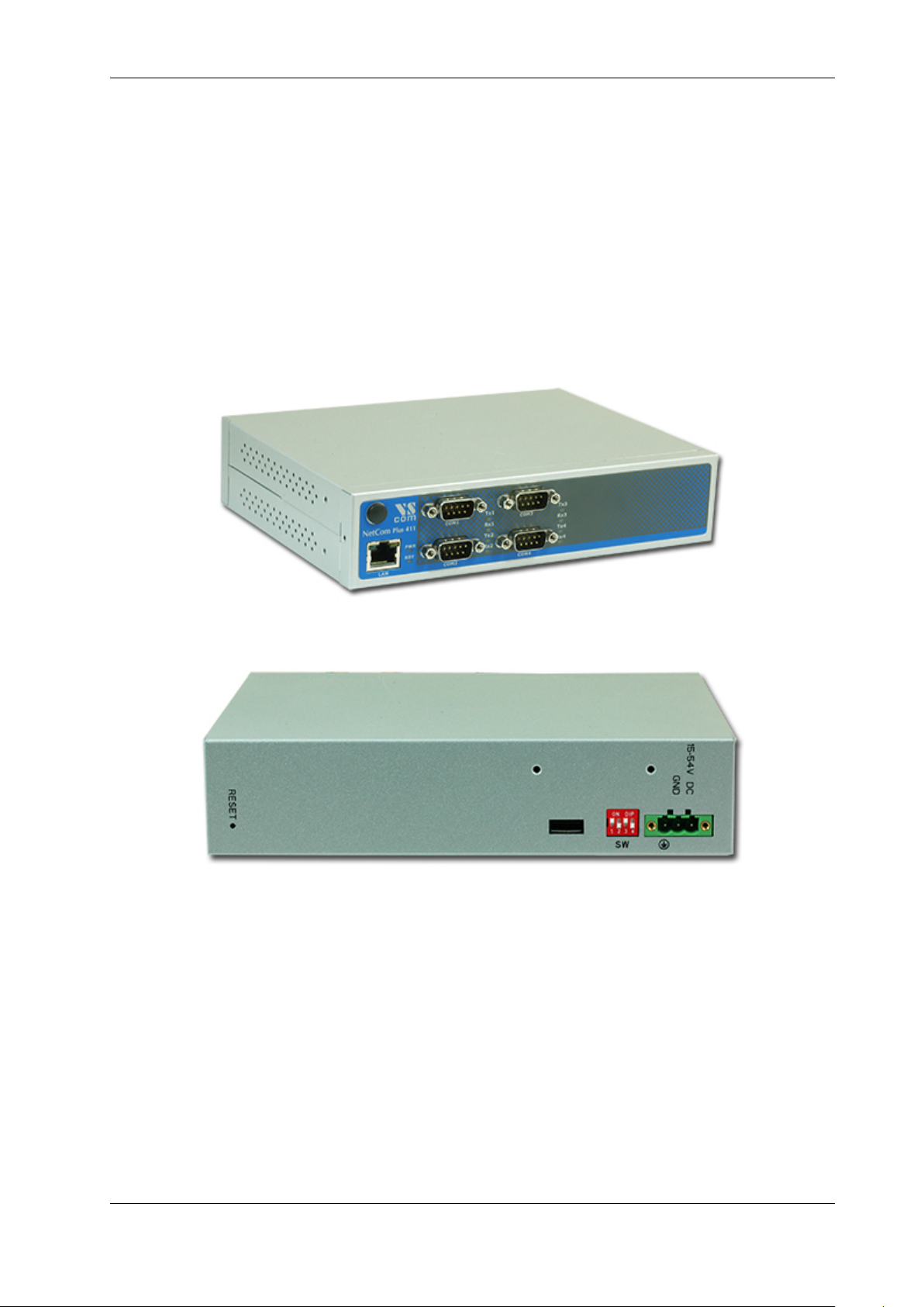
This is the ModGate Plus 413. The front side presents the four serial ports, Ethernet connector
and the position for WLAN antenna with the integrated module. The rear side shows the Reset
hole, the USB port for WLAN extension, configuration switches and the power supply.
August 2015 ModGate Plus User Manual 9

2 Introduction
ModGate Plus 813
Power requirement DC 9V to 54V, 500 mA@12V
Dimensions 196×147×44 mm3(W×D×H)
Weight 900 g
Mounting 19 inch Rack, Wall mount
POE Optional supply by Power over
Ethernet 802.3af
Table 5: Characteristics of ModGate Plus 813
(a) Front Side
(b) Rear Side
Figure 4: ModGate Plus 813
This is the ModGate Plus 813. The front side presents the eight serial ports, Ethernet connector
and the position for WLAN antenna with the integrated module. The rear side is the same as on
August 2015 ModGate Plus User Manual 10

2 Introduction
ModGate Plus 413 and shows the Reset hole, the USB port for WLAN extension, configuration
switches and the power supply.
2.3 Packing List
•ModGate Plus Modbus Gateway
•WLAN Antenna for Models with integrated module
•CD-ROM with documentation
2.4 About this Manual
This manual covers many configuration options of the ModGate Plus Modbus Gateways. The vast
majority of these are set by software, sometimes in alternative methods. To emphasize these in the
text, special character styles are used.
Bold Face is used for the names of configuration options or buttons, as they are displayed in
menus or dialogs.
Slanted denotes text as displayed by the software. These are the names of parameter options,
as well as special values for multiple-choice parameters. Such values may appear in
drop-down lists, as radio buttons or just as clickable words.
Typewriter is used for sample User Input.
The version of the firmware described in this manual is 2.0.0.
August 2015 ModGate Plus User Manual 11

3 Hardware Description
3 Hardware Description
This section focuses on the options provided by the hardware of ModGate Plus Modbus Gateways.
3.1 Configuration by DIP Switch
The ModGate Plus are configured using a webbrowser with JavaScript enabled. The DIP switches
on the ModGate Plus Gateways control special configuration options.
Function S1 S2 S3 S4 Switch Positions
Configuration IP 192.168.254.254 Off Off Off Off
Factory settings Off Off Off On
Standard Operation Off Off On On
Table 6: Switch Configurations
By default the ModGate Plus Gateway uses DHCP to get a valid IP Address. When the Gate-
way is configured for a static but unknown address, Configuration IP temporarily sets it to
192.168.254.254.
For Factory Settings the DIP switch is first set to the defined configuration. The parameters are
restored on Power-Up/Reset of the ModGate Plus Gateway. Wait until the Power LED blinks
once. Then change the DIP switch to Standard Operation and reboot the Gateway.
Standard Operation is the configuration to use for operating in Gateway mode.
3.2 Signal Assignment
It is very important to know the exact location of the serial signals in the configured mode. Here
is the table for the DB9 male connector.
Pin RS232 RS422/RS485 4-wire RS485 2-wire
1 DCD Tx−(A) Data−(A)
2 RxD Tx+(B) Data+(B)
3 TxD Rx+(B)
4 DTR Rx−(A)
5 GND GND GND
6 DSR
7 RTS
8 CTS
Table 7: Signal Assignment DB9 male
Figure 5: Connector DB9 male
August 2015 ModGate Plus User Manual 12

3 Hardware Description
For RS232 the assignment is the same as on any PC (Com1/2). This is required by RS232.
Please note the GND signal in RS485 modes (and RS422). This signal must also be connected
between the serial devices. So in reality there is not a 2-wire connection. With the exception of
very special configurations, a serial cable without GND violates the specifications for RS485.
3.3 RS485 Electrical Configuration
In typical RS485 installations certain electric conditions have to be configured. Simply connecting
cables is not enough to fulfill the specifications of RS485. For ease of installations the ModGate
Plus Gateways provide these functions for often used parameters. They are activated by software.
3.3.1 Termination Resistors
The use of long communication lines in RS485 mode requires the installation of termination resis-
tors. These must match the impedance of the cable. Typical cables in Twisted-Pair configuration
have an impedance of about 120Ω. In RS485 the typical configuration requires one resistor at each
end of the cable. This resistor is activated via the webbrowser.
3.3.2 BIAS Function
RS485 requires a BIAS option for the communication lines. This will guarantee stable electrical
levels on the cables, even at times when no station is transmitting data. Without BIAS there will
be noise on the cable, and sometimes receivers can not detect the first characters of a beginning
communication.
The serial ports of the ModGate Plus Gateways do not require adding BIAS. This function can be
added to the cable for other hardware on the RS485 bus.
3.4 Network
The ModGate Plus connects to Ethernet, and with WLAN option it may use Wireless LAN or
Ethernet at customers choice. Both interfaces are enabled and configured, a ModGate Plus with
WLAN accepts connections in parallel.
3.4.1 WLAN Configuration
The pre-defined operation mode is as Access Point, providing an open wireless network. Any
computer with WLAN equipment may contact the ModGate Plus with WLAN. This operation
mode is implemented to assist modern Windows and other operating systems, where the Ad-hoc
Mode is removed.
However the AP-Mode is not encrypted by default. As one result any station can read the data
transferred to the ModGate Plus with WLAN. This also includes the passwords. Therefore the
recommended method is to use the Ethernet connector for the first configuration.
The configuration of the WLAN parameters should follow in a later step. This is especially the
case, if encryption or certain other parameters require special configuration.
August 2015 ModGate Plus User Manual 13
3 Hardware Description
3.4.2 WLAN Antenna
The connector used for the WLAN Antenna is known as SMA-Reverse. This is a standard type
to allow for simple connection of different equipment. Just fit the supplied antenna by carefully
screwing it to the connector. You are free to connect a cable and a different antenna of your choice,
as long as it is designed for WLAN. When a ModGate Plus with WLAN detects an operational
WLAN it can connect to, the Blue LED lights.
3.4.3 Ethernet
The connector for Ethernet is the usual RJ45. Simply connect it to your (switching) Hub. Because
the Ethernet has Auto-MDI(X) function, a direct cable or a cross-over cable may both be used.
When the connect is done the Link LED on ModGate Plus (yellow) will light. When data traffic
occurs on the network, this LED will blink. It depends on your network whether a 1000 Mbit,
a 100 Mbit or a 10 Mbit connect will be established. A 1000 Mbit net causes the Speed LED on
ModGate Plus (green) to light, otherwise it will remain dark.
Red LED Yellow LED Green LED Status
Off – – Device off, no power
On Off Off No connection
On On Off 10/100 Mbit connection established
On Blink Off 10/100 Mbit data transfer (traffic)
On On On 1000 Mbit connection established
On Blink On 1000 Mbit data transfer (traffic)
Table 8: Ethernet LED Function
3.5 Power Supply
The ModGate Plus device is powered by a single 9-54V power supply. It requires 300 mA up to
600 mA of current, depending on the device type and voltage supplied. A suitable power supply
adapter is available as optional accessory. Connect the cable to the power jack (Terminal Block)
at the rear side of ModGate Plus, and put the adapter into the socket.
You may connect a power supply of your choice, providing the technical requirements are met.
August 2015 ModGate Plus User Manual 14
4 Configuration
4 Configuration
The ModGate Plus provide a webinterface for configuration. The IP Address of ModGate Plus is
used as the location to open by the web browser. Typically the IP Address is known to the user,
so this is an easy step. But this is not always the situation.
The ModGate Plus may use DHCP, which is also the default configuration. If a DHCP server is
available, it will assign an IP Address from a configured pool. At first this address is not known to
the user, since he can not access the DHCP servers log file. To solve this problem the ModGate
Plus uses UPnP. This mechanism announces the existence of ModGate Plus, so it will appear in
the Network Places of Windows.
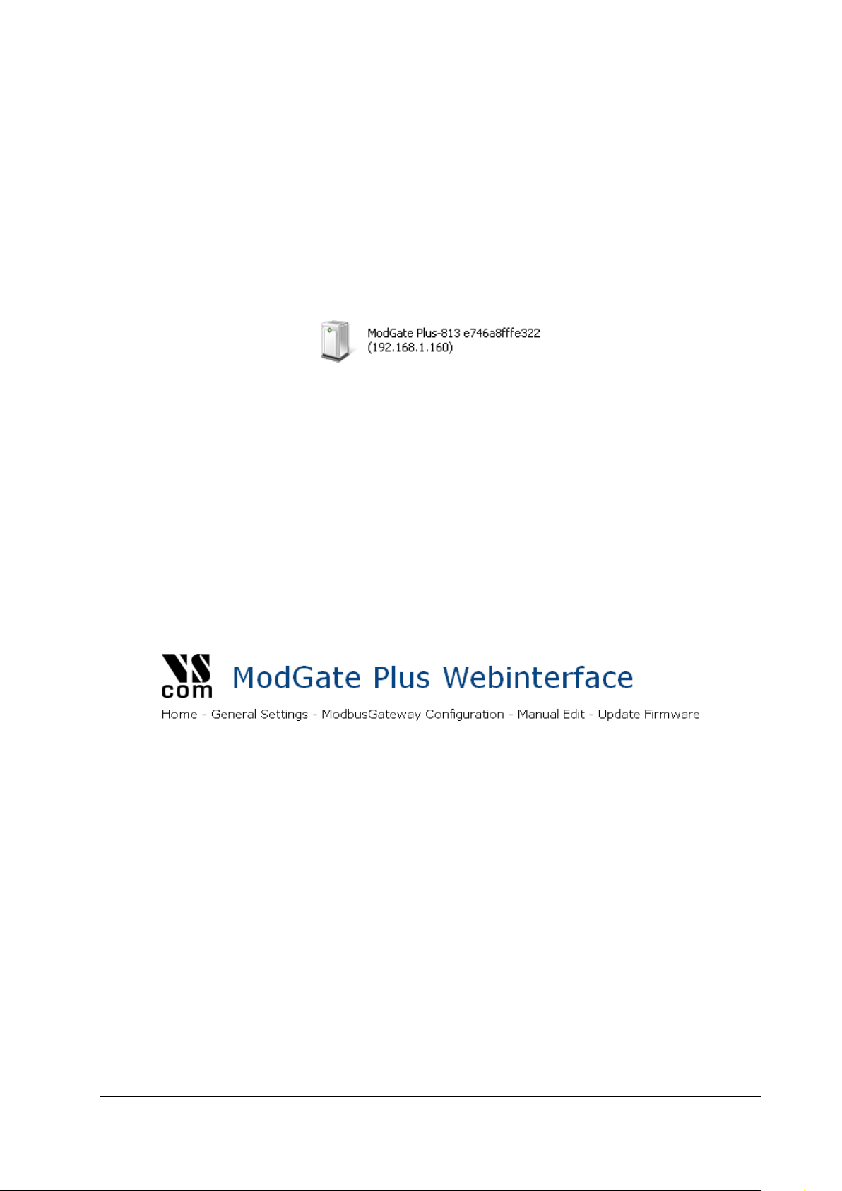
Figure 6: UPnP Device Display
Next to the icon the detected model is shown. The Ethernet MAC address (without colons) is shown
as well, so users can identify the device they wish to configure. The text displays the IP Address
in parentheses, to make access possible. More easy, a double-click will open the browser with the
configuration.
If no DHCP server is available, ModGate Plus uses the configured fixed IP Address. If this address
matches the configuration of the PC, UPnP is functional in the same way for getting access. If
the fixed address does not match the PC configuration, the user can either reset the ModGate
Plus to factory settings, or switch the ModGate Plus to the temporary configuration address
192.168.254.254 (see section 6 on page 12).
Accessing the configuration requires username and password, by default they are admin and vscom.
Figure 7: Navigation Bar
The navigation is done in the line on top of the parameters. Select the Home page, the General
Settings or the ModbusGateway Configuration. The option of Manual Edit is reserved for
special purposes, and not a supported user configuration so far. It is documented below (4.5).
Finally Update Firmware is the access to update the Firmware on the ModGate Plus.
4.1 Home
The Home page provides some Status information about the ModGate Plus to configure, as well
as some Actions the user can perform.
August 2015 ModGate Plus User Manual 15
4 Configuration
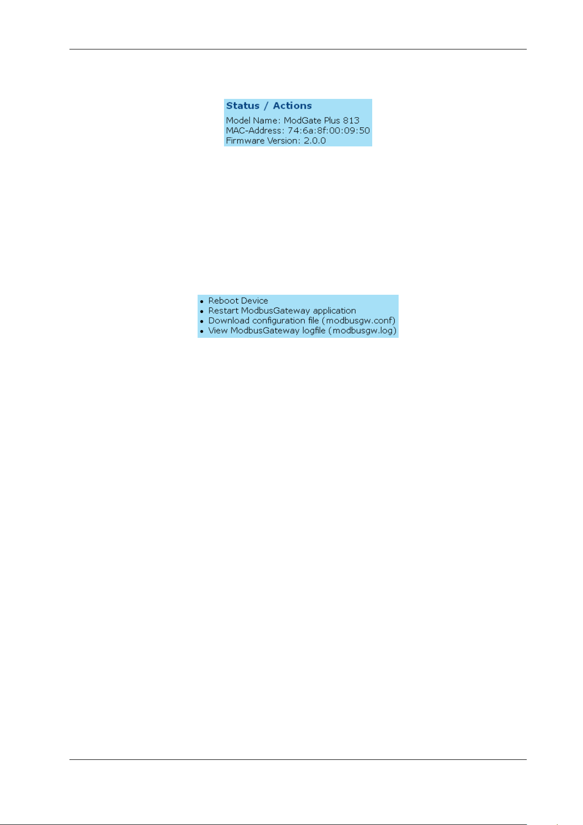
4.1.1 Status
Figure 8: Status information
The type of ModGate Plus is shown as the Model Name. For identification the MAC-Address
is also given. Since such an address must be unique for all devices on the world, this is suitable
to check if the configuration starts on the correct device. And last the Firmware Version is
presented.
4.1.2 Actions
Figure 9: Possible Actions
These Actions are required later, so they will be referenced in below sections. Here is only basic
information.
•Reboot Device
This will restart the complete ModGate Plus, thus cancelling all current operations and
connections.
•Restart application
The application is the Gateway part of the software.
•Download configuration file
The file is shown in a separate browser window. The download is performed by just saving
the ’page’. For service requests it is useful to send this saved configuration.
•View logfile
The log displays the operations performed recently. It is also shown in a separate window,
and can be saved in the same way as the configuration. Also useful for service requests.
August 2015 ModGate Plus User Manual 16
4 Configuration
4.2 General Settings
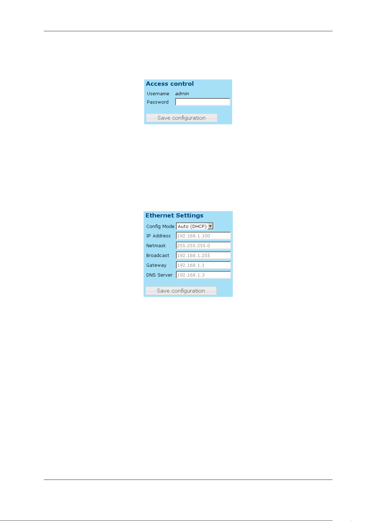
4.2.1 Access Control
Figure 10: Access Control
It is recommended to change the password to the webinterface for security reasons. The username
is fixed as admin. The factory password is vscom. Note: You have to reboot the device for the
changes to take effect.
4.2.2 Ethernet (IP) Settings
Figure 11: Ethernet Settings
Ethernet is considered the most often used network connection of ModGate Plus. Therefore the
default configuration is created for automatic acquire of suitable parameters.
Config Mode provides the choice between Auto (DHCP) and Manual. DHCP acquires the con-
figuration from a certain server in the network, no need to define the other parameters.
Selecting Manual requires to configure all following parameters, except of Gateway
and DNS Server, if they are not known. Ask your Network Administrator for proper
parameters.
IP Address is the fixed IP Address as given.
Netmask is the required Netmask.
Broadcast is the target address to use for sending out IP Broadcasts packages. Ask your Admin-
istrator.
Gateway This is the address of a Router, giving access to other networks (e.g. the Internet).
DNS Server This server translates Domain names like vscom.de to IP Addresses.
August 2015 ModGate Plus User Manual 17
4 Configuration
Note: You have to reboot (see 4.1.2) the device for the changes to take effect.
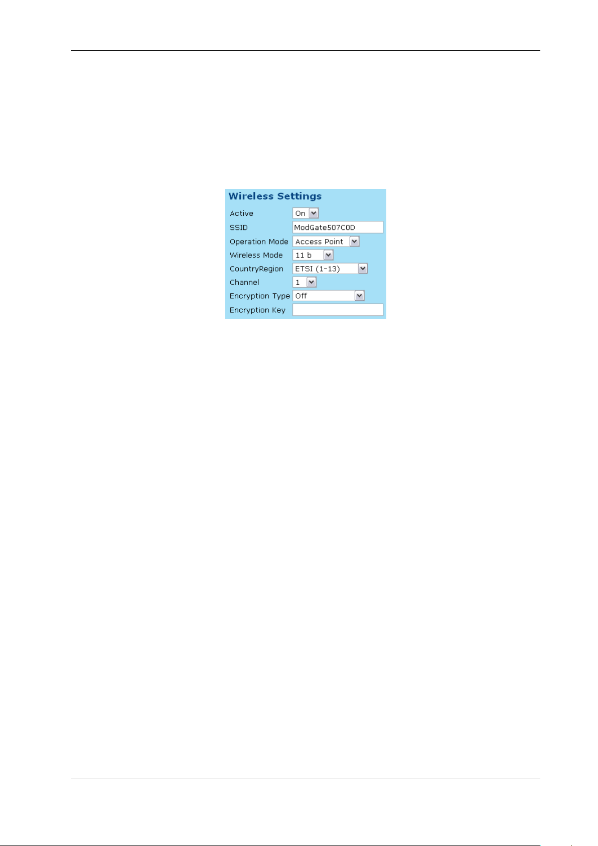
4.2.3 WLAN Settings
Models ModGate Plus with WLAN provide Wireless LAN as of IEEE 802.11b/g/n. This network
can operate in parallel to the Ethernet.
Figure 12: WLAN Radio Cell Settings
WLAN Radio Cell Parameters These are the parameters to configure the radio operation, so
ModGate Plus will operate on WLAN.
SSID is the name selected for the Radio Cell. The SSID has to be the same for devices to
communicate with each other. It is initialized with a unique string, generated from the
last characters of the Ethernet MAC Address.
Operation Mode provides the choice between Access Point and Infrastructure. The Ad-hoc
mode used in the past is no longer available in modern versions of Windows and other
operating systems. Therefore it is replaced here by the mode of Access Point, which also
allows a PC to establish a direct connection to the ModGate Plus. In Infrastructure
Mode all communication is sent via an Access Point on-site, which operates as the
central hub of the Radio Cell. In general this also enhances signal quality, security and
bandwidth.
Wireless Mode may be selected as 11b for 11 Mbit/s or 11b+g+n for up to 150 Mbit/s.
CountryRegion WLAN is a Radio technique, so local regulations apply. These are selected
by country. FCC(1-11) is valid in North America, and ETSI(1-13) generally in Eu-
rope. SPAIN(10-11) and FRANCE(10-13) are special European configurations, finally
MKK(14) is required for Japan. Please check local restrictions on allowed radio chan-
nels.
Channel selects the frequency the cell shall operate on. The previous parameter of CountryRe-
gion may restrict the possible configurations.
Encryption Type is used to restrict access to the radio cell. The possible selections Off,WEP,
WPA-PSK TKIP and WPA2-PSK AES, where WPA2 is the most secure variant.
August 2015 ModGate Plus User Manual 18
4 Configuration
Encryption Key This is the secret key which provides access to the radio cell. Without this key
no station can join the Wireless network. The length of the string defines the strength
of the key.
•WEP with 5 characters: WEP-40/64 with 40 bit text key
•WEP with 10 characters: WEP-40/64 with 40 bit binary key (hexadecimal)
•WEP with 13 characters: WEP-114/128 with 114 bit text key
•WEP with 26 characters: WEP-114/128 with 114 bit binary key (hexadecimal)
•WPA/WPA2 with 8 to 63 characters: The 256 bit key is generated from this text and the
SSID
•WPA/WPA2 with 64 characters: The 256 bit binary key (hexadecimal) is directly given
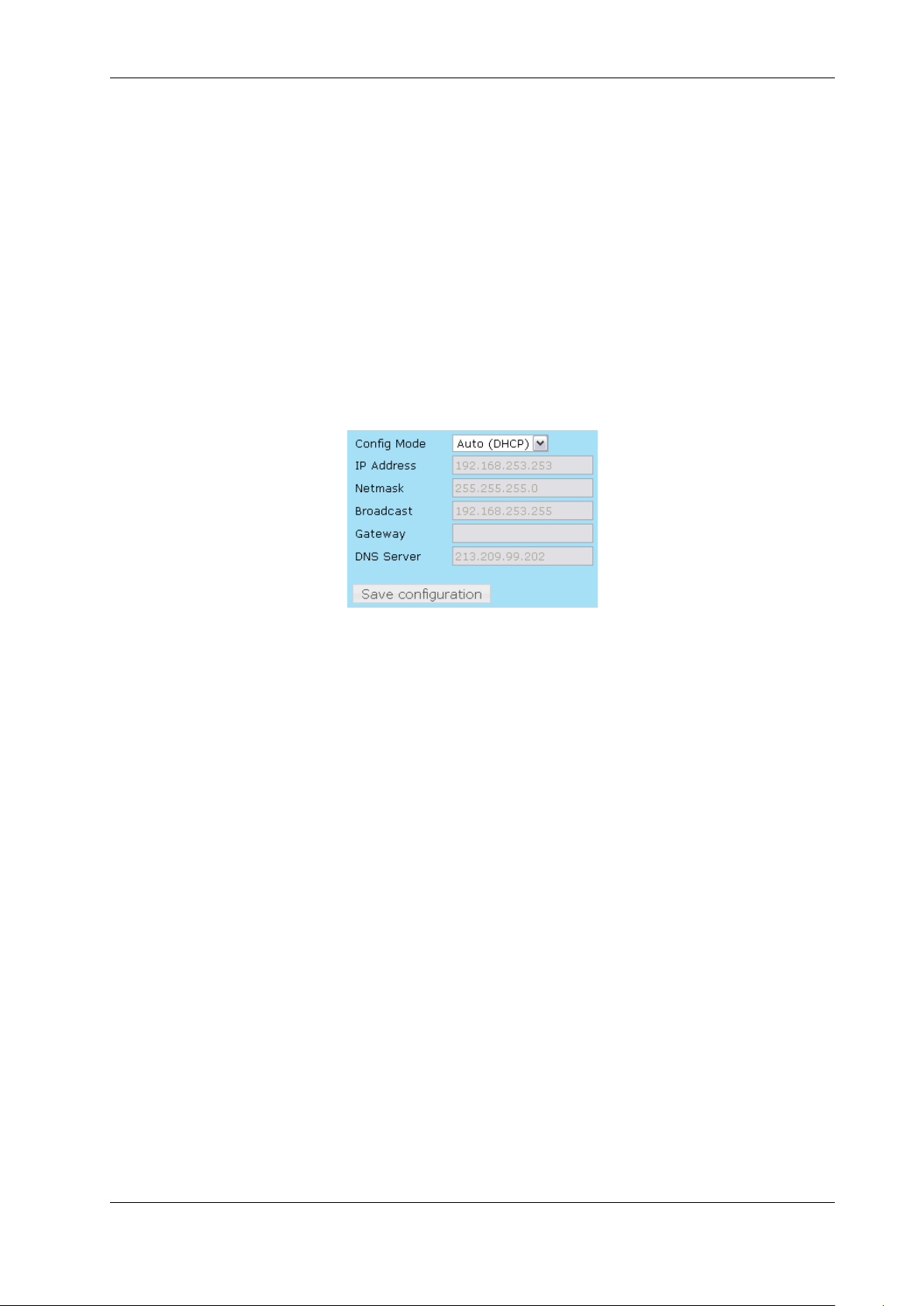
Figure 13: WLAN IP Settings
WLAN IP Settings When ModGate Plus has access to the WLAN radio cell, this network inter-
face operates similar to Ethernet. Meaning all IP traffic operates exactly the same on Ethernet or
WLAN. This results in a configuration parallel to Ethernet. Please ask your Network Administra-
tor for a correct configuration, and compare the parameter meanings with Ethernet (see 4.2.2 on
page 17).
Note: You have to reboot (see 4.1.2) the device for the changes to take effect.
4.3 Modbus Gateway Configuration
The ModGate Plus use a versatile but powerful concept of mapping target interfaces for incoming
Modbus frames. The decision where an incoming frame has to be transferred to is chosen on few
information, so the configuration stays quite simple.
Modbus uses a Master/Slave concept of communication. Each slave device has an address, which
is unique on the line where it is connected to. The Master sends commands and requests, which
contain this address in the frame header. ModGate Plus knows which communication line (serial
port, TCP connection) the address is connected to. So it is easy to send the received frame to that
interface. Of course responses are identified and sent to the Master which requested them. This is
the DirectMappingMode.
However in many installations there is a ModGate Plus with a single serial port only. This Gateway
is contacted by only one Master via TCP. Naturally all data coming from TCP must be sent to
August 2015 ModGate Plus User Manual 19

4 Configuration
the serial port, and vice versa. It is not necessary to define all the Modbus addresses for just this
simple task. The configuration is easy in the PromiscuousMode.
Note: Changes in this section do not need a complete reboot of the device, its sufficient to restart
the ModbusGateway application (see section 4.1.2 on page 16) once the configuration is finished.
4.3.1 Modbus Gateway Settings
Figure 14: Gateway Settings
ListenAddress Specifies the IP Address the modbus gateway application listens on. The default
value is 0.0.0.0, which means ModGate Plus accepts connections on all interfaces (Ethernet
and WLAN) in parallel. Enter the IP Address of either Ethernet or WLAN to restrict the
Gateway function to this interface.
ListenPort Specifies the TCP port number the Modbus gateway application listens on. The default
value is 502, which is the reserved port for Modbus/TCP protocol.
GatewayMode Lets you specify the mode which the gateway operates in. DirectMappingMode
(Mapping of Modbus devices to serial ports or TCP connections) or PromiscuousMode (Map-
ping of serial ports to TCP connections).
Allow unknown clients Enables all stations to connect to ModGate Plus, without prior configura-
tion as an allowed target for data.
Verbose When enabled the Modbus gateway application writes more debug output in the logfile
(/var/log/modbusgw.log). Don’t enable this, unless you want to resolve problems!
The combination of PromiscousMode with Allow unknown clients is useful only for single port
models. All requests from any master on TCP is directed to the single serial port.
PromiscousMode on multi-port models requires the definition of TCP connections. This allows
the assignment of certain clients (Modbus Master) on TCP to a distinct serial port.
The DirectMappingMode routes Modbus requests to the targets based on the Modbus ID. The
requests may originate from any source, including unknown clients.
August 2015 ModGate Plus User Manual 20
Table of contents


