Vision tools 09V0002B User manual

Technical Manual
VoE-IOBox Rev. 2.0
Article-No.: 09V0002B
Version: 5.2

© Vision Tools Bildanalyse Systeme GmbH
Heinrich-Hertz-Straße 7
68753 Waghäusel
Germany
Tel.: +49 7254 –9351 0
Fax: +49 7254 –9351 200
www.vision-tools.com
Revision date:
July 2021
Version:
5.2
Version change:
Log

Table of contents
Technisches Handbuch
Version 5.2
1
1 Table of contents
1Table of contents.....................................................................1
2General .....................................................................................2
2.1 Abbreviations.................................................................................................. 2
2.2 Information on the manual.............................................................................. 2
2.3 Documents enclosed...................................................................................... 2
2.4 Safety information........................................................................................... 2
2.5 Limitation of liability ........................................................................................ 4
2.6 Copyright law.................................................................................................. 4
2.7 Guarantee and Liability................................................................................... 4
3Safety........................................................................................5
3.1 Appropriate use .............................................................................................. 5
3.2 Foreseeable misuse ....................................................................................... 6
4Technical data..........................................................................7
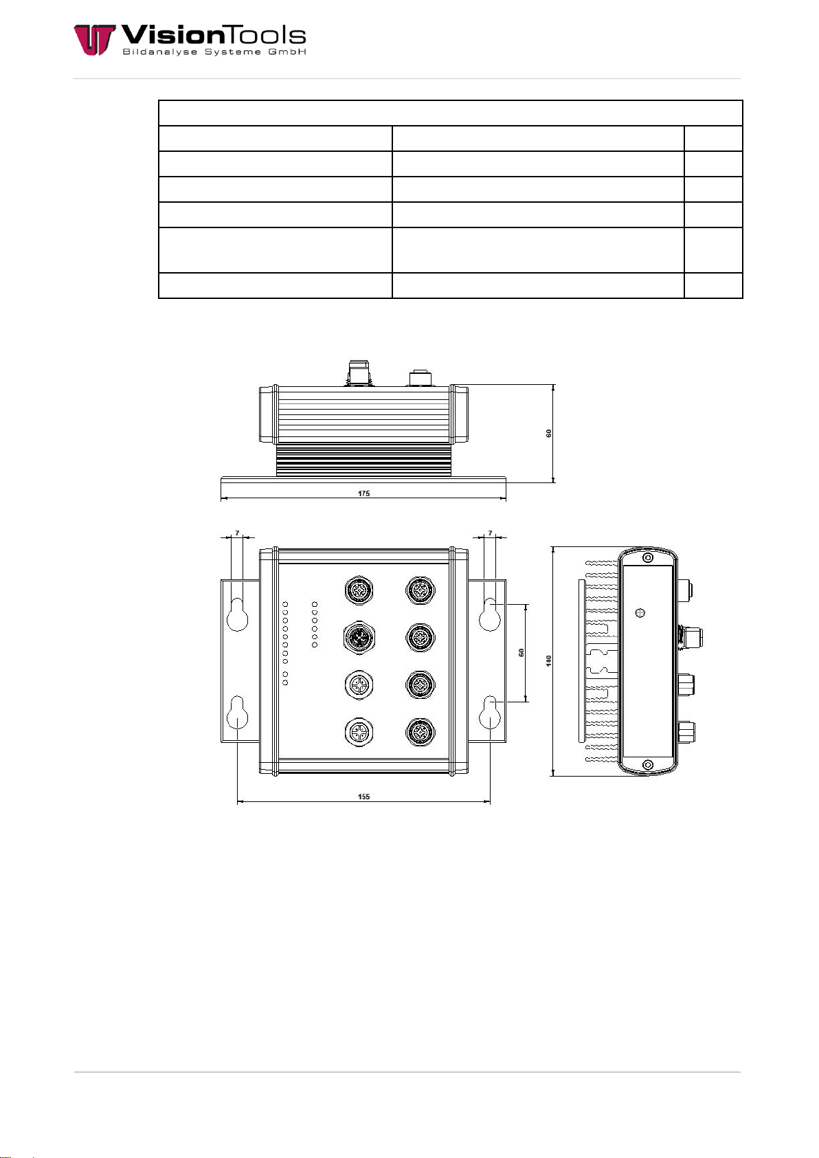
4.1 Dimensions (mm)............................................................................................ 8
4.2 Plug Position................................................................................................... 9
4.3 Status LEDs.................................................................................................... 9
4.4 Pin Assignment............................................................................................. 10
4.5 Delivery status.............................................................................................. 11
4.6 Settings......................................................................................................... 12
4.6.1 Log................................................................................................................ 12
4.6.2 Bootloader .................................................................................................... 22
4.6.3 Calibration of analogue measurement ......................................................... 22
4.6.4 Change the IP address................................................................................. 23
4.6.5 Update firmware ........................................................................................... 25
4.6.6 Setting the IP address of the network adapter............................................. 26
4.6.7 Dim lights...................................................................................................... 28
5Commissioning......................................................................29
5.1 Assembly...................................................................................................... 29
6Disposal..................................................................................30
7Notes.......................................................................................31
8Attachment.............................................................................32
8.1 Manufacturer's Declaration........................................................................... 33

General
Technisches Handbuch
Version 5.2
2
2 General
2.1 Abbreviations
The abbreviations used are explained below:
V60 = Image analysis program from the VisionTools company
PPE = personal protective equipment
I/O = Input/Output
VoE = Vision over Ethernet
GND = Ground
EMC = Electromagnetic compatibility
2.2 Information on the manual
This technical manual contains important instructions for working with the product named on
the cover sheet. The prerequisite for workplace safety is the observance of all safety and
handling instructions specified in this manual. The local accident prevention regulations and
national health and safety regulations must be observed in addition to the instructions in this
manual. All information and instructions are to be carefully read before use. The manual is a
product component and must be kept accessible to the plant operator at all times.
2.3 Documents enclosed
Manufacturer's declaration
2.4 Safety information
In this manual, icons (acc. to EN ISO 7010) are used to highlight correct text passages and
relevant sections. If the product is sold in a non-EU country, the warning symbols may need
to be amended, if necessary.
The signal word describes the severity of the impending risks:
Danger! Imminent dangerous situation which will result in serious bodily injury or death.
Warning! Potentially dangerous situation which could result in serious bodily injury or
death.
Caution! Potentially dangerous situation which could result in minor bodily injury or
death. Also warning of damage to property.
Note! For application instructions and other important information.

General
Technisches Handbuch
Version 5.2
3
Note
General information
Follow the instructions
In accordance with DIN EN ISO 7010
General warning sign
In accordance with DIN EN ISO 7010
Warning of electrical voltage
In accordance with DIN EN ISO 7010
Warning of oxidising substances
In accordance with DIN EN ISO 7010

General
Technisches Handbuch
Version 5.2
4
2.5 Limitation of liability
All information and statements in this manual are compiled in consideration of valid standards
and regulations, as well as state of the art technological knowledge.
The manufacturer accepts no liability for damages due to:
Failure to observe this manual
Inappropriate use
Using non-trained personnel
Undertaking unauthorized modifications
Using impermissible replacement parts
Additionally, the obligations, the General Terms and Conditions and delivery conditions of the
manufacturer, and the statutory regulations valid at the time the contract was concluded will
apply.
2.6 Copyright law
Copyright law to this operating manual belongs to the company VisionTools Bildanalyse
Systeme GmbH. This manual is intended only for the operator and the operator’s personnel.
It includes regulations and information that may not be
duplicated,
distributed, or
transmitted in any other manner, either in whole or in part.
Duplicating the manual within a company for the purposes of training by the operator is
excepted. Violations may have criminal consequences.
2.7 Guarantee and Liability
Our General Terms and Conditions apply. Claims for a guarantee or for liability in case of
personal injury or property damage are excluded if they are due to one or more of the
following causes.
Inappropriate use of the assembly
Inappropriate installation, commissioning, operation, and maintenance of the device or
system
Failure to follow the information in the manual regarding transportation, storage,
installation, commissioning, operation, limit values, maintenance of assemblies
Unauthorized modifications to the assemblies
Unauthorized modifications to the programmes
Lack of monitoring of components subject to wear
Catastrophic incidents due to foreign objects and force majeure
Liability for subsequent damages is excluded

Safety
Technisches Handbuch
Version 5.2
5
3 Safety
3.1 Appropriate use
The VoE IOBox provides an interface between industrial process technology and the
personal computer (PC).
It is intended for use on a PC, which is equipped with an Ethernet interface. The PC is
subject to EC Directive 89/336/EEC and must meet the EMC protection requirements.
Products that meet these requirements bear the CE mark.
The data between the VoE IOBox and the PC is exchanged via a shielded CAT6 cable with
an X-Cross connector on the side of the module. The cable is connected to the X1 socket.
The module has 6 inputs and 4 outputs for processing digital 24 V signals.
For operation of the inputs and outputs, an external 24 V supply voltage is required. The
terminals are divided into two groups with the GND potential. The inputs E1.0-E1.7 and the
outputs A1.0-A1.7 have a common GND potential as well as the inputs E2.0-E2.7 and the
outputs A2.0-A2.7.
The use of the VoE IOBox in combination with external clamping or relay boards requires
professional installation in a closed control cabinet.
Therefore check the shielding capacity of the PC housing and cable shield before using the
equipment.
Any other use or use beyond the scope of this document is deemed contrary to the
designated use. The manufacturer shall not be liable for any resulting damages.
The intended use requires compliance with all instructions in the technical manual.
Limits of use
When using the VoE IOBox, in a plant, the interference resistance and emissions of the plant
can also change. Increased emission or decreased interference resistance could means that
the conformity of the system is no longer ensured.
The VoE IOBox must remain in its original packaging until use.
Do not remove the identification numbers (serial number) of the VoE IOBox. To do so
will result in loss of the warranty.

Safety
Technisches Handbuch
Version 5.2
6
3.2 Foreseeable misuse
Any other use besides that determined in Appropriate use this chapter or any use extending
beyond this is not appropriate!
The operator will bear sole responsibility
for any damages that may result from such use.
the company VisionTools accepts no liability.
In case of changes or unauthorized modifications to the system, any liability or guarantee
from VisionTools Bildanalyse Systeme GmbH will cease to exist.
The electromagnetic behaviour of the system can be impaired by additions or changes of any
kind.
Therefore, make no changes or additions to the system without consulting with the company
VisionTools Bildanalyse Systeme GmbH and receiving written approval to do so.
Danger!
Dangers may occur following improper use.

Technical data
Technisches Handbuch
Version 5.2
7
4 Technical data
Housing
Aluminium diecast (IP65)
Unit
Dimension (LxBxH)
130x140x76 (without plug)
mm
Temperature limit
Operating temperature
0 to 60
°C
Storage temperature
-15 to 70
°C
Humidity
30 –99 whitout condensation
%
Electrical limits
PoE voltage
max. 56
V
PoE current
max. 1.2
A
X2 voltage
max. 30
V
X2 current
max. 12
A
Inputs (IN)
Type
positive switching
Voltage
max. 30
V
Current
5
mA
Connection type
M12 Male-Connector 4pos. A-Coded
Outputs (OUT 24)
Type
positive switching
Voltage
24
V
Current
max. 4 / in total max. 12
(depending on the power supply)
A
Connection type
M12 Female-Connector 4pos. A-Coded
Outputs (OUT PW)
Type
push-pull
Voltage
24
V
Current
max. 200
mA
Frequency
1.5
kHz
min. pulse width (duty factor 1%)
6.7
µs
Connection type
M12 Female-Connector 4pos. A-Coded
Interface
Type
Ethernet 10
MBit/s
Connection type
M12 Female-Connector 8pos. X-Coded

Technical data
Technisches Handbuch
Version 5.2
8
Power X2
Type
Power supply
Voltage
max. 30
V
Current
max. 12
A
Connection type
M12 Male-Connector 4pos. T-Coded
Current drain without load
(idle)
approx. 0.1
A
Power consumption without load
approx. 2.4
W
4.1 Dimensions (mm)

Technical data
Technisches Handbuch
Version 5.2
9
4.2 Plug Position
4.3 Status LEDs
LED label
Meaning
LINK
The VoE-IOBox is connected and supplied with power.
DATA
Data transmission takes place, or data packages are
transmitted.
O1.24 –O4.24
Outputs 1, 2, 3 or 4 are switched.
O1.PW –O4.PW
Outputs 1, 2, 3, or 4 were switched via the PWM duty factor [%].
IN1 –IN6
Inputs 1, 2, 3, 4, 5 or 6 are switched.
PoE
The power supply is via PoE.
24V
The power supply is via 24V.

Technical data
Technisches Handbuch
Version 5.2
10
4.4 Pin Assignment
X1 Ethernet
X5 Output
M12 Female-Connector 8pos.
X-Coded
PIN
Signal
1
MX0+
2
MX0-
3
MX1+
4
MX1-
5
MX3+
6
MX3-
7
MX2-
8
MX2+
M12 Female-Connector 4pos.
A-Coded
PIN
Signal
1
24V
2
GND
3
GND
4
PWM
X2 Power 24V
X6 Output
M12 Male-Connector 4pos.
T-Coded
PIN
Signal
1
24V
2
GND
3
GND
4
24V
M12 Female-Connector 4pos.
A-Coded
PIN
Signal
1
24V
2
GND
3
GND
4
PWM
X3 Input
X7 Output
M12 Male-Connector 4pos.
A-Coded
PIN
Signal
1
INB/24V
2
INC
3
GND
4
INA
M12 Female-Connector 4pos.
A-Coded
PIN
Signal
1
24V
2
GND
3
GND
4
PWM
X4 Input
X8 Output
M12 Male-Connector 4pos.
A-Coded
PIN
Signal
1
INB/24V
2
INC
3
GND
4
INA
M12 Female-Connector 4pos.
A-Coded
PIN
Signal
1
24V
2
GND
3
GND
4
PWM

Technical data
Technisches Handbuch
Version 5.2
11
4.5 Delivery status
MAC
individual
IP address
192.168.0.254
Subnetwork mask
255.255.255.0
Gateway
192.168.0.1
DNS1
192.168.0.1
DNS2
0.0.0.0
TCP/IP Port
9760
To return the device to the delivery status, the RESET button must be pressed until the LED
on the left of the RESET button begins flashing.
Then adjust the IP address in the "TCP/IP-Client - Init" object (see chapter Change the IP
address) and briefly switch the box off.
NOTE!
Only the power supply may be connected for resetting.
The video "How to reset the VoE IO-Box.mp4" serves as an additional
help.

Technical data
Technisches Handbuch
Version 5.2
12
4.6 Settings
4.6.1 Log
The commands are sent and received to the VoE-IOBox via "TCP-IP". The correct IP address
as well as the correct port must be entered.
All commands are sent in plain text (ASCII). Values begin with an angle bracket and end with
an angle bracket. Values are sent as decimal values in plain text (ASCII). If a command is not
understood or is wrong, the module sends "ENR<X>".
1. Example (read out limit values of the outputs):
Command to read: RCRL1 (1 to 4 are the outputs of the VoE-IOBox)
2. Example (read error):
Command to read: ERR (Result 99 = over-current)

Technical data
Technisches Handbuch
Version 5.2
13
Configure CIP/RCIP IP addresses
Write:
CIP<IPAddr,Mask,Gateway,DNS1,DNS2,HostName>
Answer: none
_CIP<IPAddr,Mask,Gateway,DNS1,DNS2,HostName>
Answer: „ACK“
E.g. CIP<192.168.0.10,255.255.255.0,192.168.0.1,0.0.0.0,VOE_HOST>
Read:
RCIP
Answer: CIP<MACAddr,IPAddr,Mask,Gateway,DNS1,DNS2,HostName>
E.g.: CIP<00:04:A3:D0:00:00,192.168.0.10,255.255.255.0,192.168.0.1,0.0.0.0,VOE_HOST>
RVER Returns the program version
Read:
RVER
Answer: VER<vX.XX.XX>
UPL Upload Mode
Send:
UPL
Answer: UPL<vX.XX.XX>
The controller is set to upload mode for 4 seconds. See Bootloader.
TEST starts and stops the test run.
Send:
TEST
Answer: TEST<1>
Answer: TEST<0>
The controller is set to test mode.
CADC Calibration of the analogue measurement
Send:
CADC
Answer: RVER<vX.XX.XX>
See Calibration of analogue measurement.

Technical data
Technisches Handbuch
Version 5.2
14
SPA memory parameter
Send:
SPA
Answer: SPA
Transmitted parameters such as CFIx<>, CFOx<>, TMRx<> and CRL<> are not immediately
permanently stored in the EEPROM of the VoE-IOBox. Only with the command SPA are the
parameters stored permanently and are then still available after a restart.
EXCEPTION CIP<> is stored immediately.
CFI/RCFI Setting the inputs IN1...6
Write:
CFI1<PORT,EVENT,MODE,Debounce time>
Answer: none
_CFI1<PORT,EVENT,MODE,Debounce time>
Answer: „ACK“
CFI1<0..4,0..4,0..1,0..999>
Specifies the output to be switched.
0 = not assigned to any output, 1 = OUT1, 2 = OUT2, 3 =
OUT3, 4 = OUT4
CFI1<0..4,0..4,0..1,0..999>
0 = Input static. Output remains on as long as the input is
present.
1 = positive edge.
Output switches on with rising edge for the time programmed
with TMR1<...>.
2 = negative edge.
Output switches on with falling edge for the time programmed
with TMR1<...>.
3 = positive edge.
Output switches on/off with rising edge (impulse relay).
4 = negative edge.
Output switches on/off with falling edge (impulse relay).
CFI1<0..4,0..4,0..1,0..999>
0 = polling input.
1 = push input.
If the input state changes, INP1<0> or INP1<1> is transmitted.
CFI1<0..4,0..4,0..1,0..999>
0..999 ms debouncing for IN1.
CFI2<x,x,x,xxx>
see CFI1<x,x,x,xxx>
CFI3<x,x,x,xxx>
see CFI1<x,x,x,xxx>
CFI4<x,x,x,xxx>
see CFI1<x,x,x,xxx>
CFI5<x,x,x,xxx>
see CFI1<x,x,x,xxx>
CFI6<x,x,x,xxx>
see CFI1<x,x,x,xxx>

Technical data
Technisches Handbuch
Version 5.2
15
Read:
RCFI1
Answer: CFI1<0..4,0..4,0..1,0..999>
RCFI2
Answer: CFI2<0..4,0..4,0..1,0..999>
RCFI3
Answer: CFI3<0..4,0..4,0..1,0..999>
RCFI4
Answer: CFI4<0..4,0..4,0..1,0..999>
RCFI5
Answer: CFI5<0..4,0..4,0..1,0..999>
RCFI6
Answer: CFI6<0..4,0..4,0..1,0..999>
RINP Reads the inputs IN1...6
RINP1
Answer: INP1<0..1>
RINP2
Answer: INP2<0..1>
RINP3
Answer: INP3<0..1>
RINP4
Answer: INP4<0..1>
RINP5
Answer: INP5<0..1>
RINP6
Answer: INP6<0..1>
CFO/RCFO Sets the outputs OUT1...4
Write:
CFO1<MODE,Delay>
Answer: none
_CFO1<MODE,Delay >
Answer; „ACK“
CFO1<0..1,0..9999>
0 = OUT1.24 = Switch, OUT1.PW = PWM (pulse width modulation)
1 = OUT1.24 = PWM, OUT1.PW = off
CFO1<0..1,0..9999>
0..9999 ms Switch-on delay OUT1.
CFO2<x,xxxx>
see CFO1<x,xxxx>
CFO3<x,xxxx>
see CFO1<x,xxxx>
CFO4<x,xxxx>
see CFO1<x,xxxx>
Read:
RCFO1
Answer: CFO1<0..1,0..9999>
RCFO2
Answer: CFO2<0..1,0..9999>
RCFO3
Answer: CFO3<0..1,0..9999>
RCFO4
Answer: CFO4<0..1,0..9999>

Technical data
Technisches Handbuch
Version 5.2
16
OUT/ROUT Switches the outputs OUT1…4
Write:
OUTx<STATUS>
Answer: none
_OUTx<STATUS>
Answer: „ACK“
OUT1<0..1>
0 = Switches OUT1 off
with CFO1<0,xxxx> Output OUT1.24 is switched off and the PWM signal
at output OUT1.PWM is stopped.
with CFO1<1,xxxx> the PWM signal is stopped at Output OUT1.24.
1 = Switches OUT1 on
with CFO1<0,xxxx> Output OUT1.24 is switched on and the PWM signal
at Output OUT1.PWM is output.
with CFO1<1,xxxx> the PWM signal is output at Output OUT1.24.
OUT2<x>
see OUT1<x>
OUT3<x>
see OUT1<x>
OUT4<x>
see OUT1<x>
Read:
ROUT1
Answer: OUT1<0..1>
ROUT2
Answer: OUT2<0..1>
ROUT3
Answer: OUT3<0..1>
ROUT4
Answer: OUT4<0..1>
OUTP Switches the outputs OUT1...4 with PWM value
Write:
OUTPx<STATUS,PWM>
Answer: none
_OUTPx<STATUS,PWM>
Answer: „ACK“
OUTP1<0..1,0..100>
0 = Switches OUT1 off
with CFO1<0,xxxx> Output OUT1.24 is switched off and the PWM
signal at output OUT1.PWM is stopped.
with CFO1<1,xxxx> the PWM signal is stopped at Output OUT1.24.
1 = Switches OUT1 on
with CFO1<0,xxxx> Output OUT1.24 is switched on and the PWM
signal at Output OUT1.PWM is output.
with CFO1<1,xxxx> the PWM signal is output at Output OUT1.24.
OUTP1<0..1,0..100>
0..100% Brightness for OUT1.

Technical data
Technisches Handbuch
Version 5.2
17
OUTP2<x,xxx>
see OUTP1<x,xxx>
OUTP3<x,xxx>
see OUTP1<x,xxx>
OUTP4<x,xxx>
see OUTP1<x,xxx>
OUT0 Simultaneous switching of the outputs OUT1…4
Write:
OUT0<OUT1,OUT2,OUT3,OUT4>
Answer: none
_OUT0< OUT1,OUT2,OUT3,OUT4>
Answer: „ACK“
OUT0<0.X.1,0.X.1,0.X.1,0.X.1>
0 = Switches OUTx off
with CFO1<0,xxxx> Output OUT1.24 is switched off and
the PWM signal at output OUT1.PWM is stopped.
with CFO1<1,xxxx> the PWM signal is stopped at Output
OUT1.24.
1 = Switches OUTx on
with CFO1<0,xxxx> Output OUT1.24 is switched on and
the PWM signal at Output OUT1.PWM is output.
with CFO1<1,xxxx> the PWM signal is output at Output
OUT1.24.
X = no change at OUTx
OUTP0 Simultaneous switching of outputs OUT1...4 with PWM value
Write:
OUTP0<OUT1,PWM1,OUT2,PWM2,OUT3,PWM3,OUT4,PWM4>
Answer: none
_OUTP0<OUT1,PWM1,OUT2,PWM2,OUT3,PWM3,OUT4,PWM4>
Answer: „ACK“
OUTP0<0.X.1,0..100,..
..,0.X.1,0..100>
0 = Switches OUTx off
with CFO1<0,xxxx> Output OUT1.24 is switched off and the PWM
signal at output OUT1.PWM is stopped.
with CFO1<1,xxxx> the PWM signal is stopped at Output OUT1.24.
1 = Switches OUTx on
with CFO1<0,xxxx> Output OUT1.24 is switched on and the PWM
signal at Output OUT1.PWM is output.
with CFO1<1,xxxx> the PWM signal is output at Output OUT1.24.
X = no change at OUTx
OUTP0<0.X.1,0..100,..
..,0.X.1,0..100>
0..100% Brightness for OUTx.

Technical data
Technisches Handbuch
Version 5.2
18
PSS/RPSS Switches the outputs PSS1…2 on
Write:
PSS1<STATUS>
Answer: none
_PSS1<STATUS>
Answer: „ACK“
PSS1<0..1>
0 = Switches PSS1 off
1 = Switches PSS1 on
Switches at X3.1 24Volt on/off. Used to supply voltage to a connected
sensor with max. 200mA.
PSS2<x>
see PSS1<x>
Switches at X4.1 24Volt on/off. Used to supply voltage to a connected
sensor with max. 200mA.
Read:
RPSS1
Answer: PSS1<0..1>
RPSS2
Answer: PSS2<0..1>
TRG Software trigger for Outputs OUT1…4
Write:
TRG1<TIME>
Answer: none
_TRG1<TIME>
Answer: „ACK“
TRG1<0…9999>
0..9999 ms Duty cycle for OUT1
with CFO1<0,xxxx> Output OUT1.24 is switched on and the PWM signal
at Output OUT1.PWM is output. After the time has elapsed, both outputs
are switched off.
with CFO1<1,xxxx> the PWM signal is output at Output OUT1.24. After
the time has elapsed, the output is switched off.
TRG2<xxxx>
see TRG1<xxxx>
TRG3<xxxx>
see TRG1<xxxx>
TRG4<xxxx>
see TRG1<xxxx>
If TRG1..4 is sent with empty brackets "<>", the time of TMR1..4 is taken.
Table of contents
Other Vision tools Control Unit manuals