manuals.online logo
Brands
  1. Home
  2. •
  3. Brands
  4. •
  5. Dormakaba
  6. •
  7. Control Unit
  8. •
  9. Dormakaba SIO-DR User manual

Dormakaba SIO-DR User manual

WN 059731 45532 – 2019-04
EN
SIO-DR
Mounting instructions
1 About this document
1.1 Contents and purpose
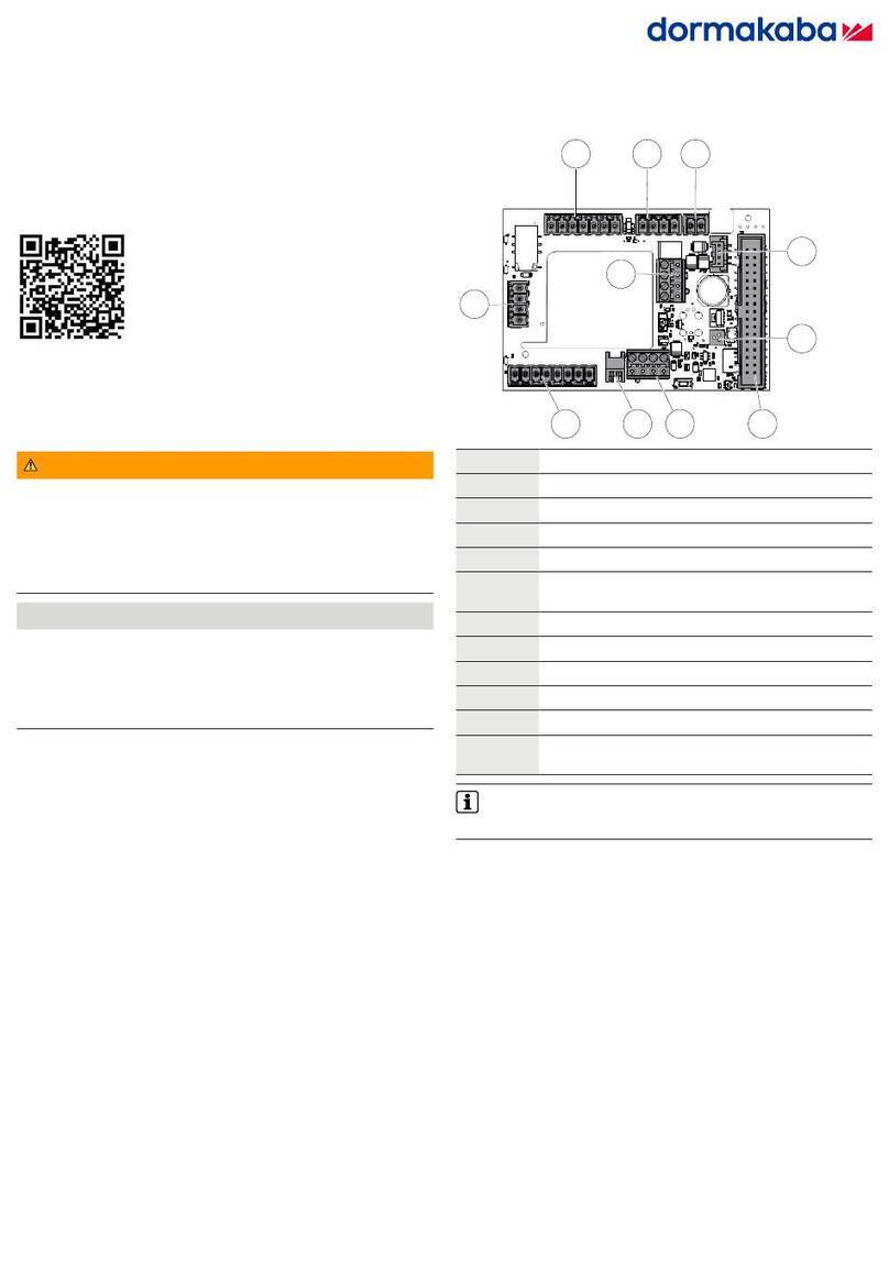
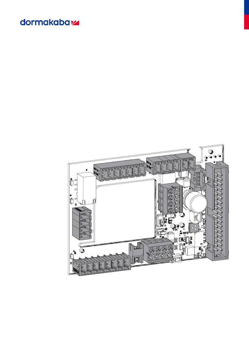
This document describes the mounting of the SIO-DR
module.
1.2 Target group
This document is intended for assembling technicians
and specialists authorized for mounting by
dormakaba.
1.3 Other applicable documents
• Instructions for devices intended for networking
1.4 Symbols used
1. 2. Sequence of action steps
6Reference to a chapter
Components may be damaged by
electrostatic discharge. Ground
your own body before touching a
component!
2 Safety
2.1 Intended use
The SIO-DR module is used to connect analog switch
contacts to the dormakaba system bus. Messages are
output via contacts or control signals are read in.
2.2 Personnel qualification
Mounting may only be carried out by persons
authorized by dormakaba.
3 Product description
The SIO-DR module is a DCW® component. Status
messages are output potential-free via relays. Control
signals are read in via optocouplers.
The mounting takes place on a 35 mm DIN rail in
a housing. The housing must at least meet the
requirements of IP 30.
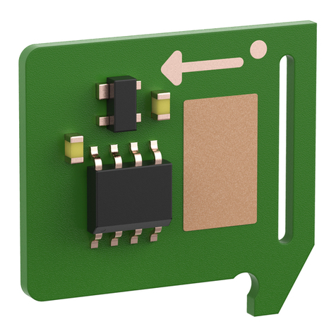
3.1 Parts included
106
92
65
Contents
1 About this document 1
2 Safety 1
3 Product description 1
4 Mounting 2
5 Disassembly and disposal 4
2SIO-DR 2019-04
WN 059731 45532
dormakaba Mounting instructions Mounting
4 Mounting
4.1 Mount the SIO-DR
5.1
J-Y(St)Y
2x2x0.8
1.
2.
1
2
1.
4.2 Assignment of terminals and switches
Out 1Out 2Out 3Out 4
GND 24V
NO
C
NC
NO
C
NC
NO
C
NC
NO
C
NC
GND 24V
DCW
In 1In 2 In 3 In 4 GND 24V1AB3
GND 24V1AB3
Addr
X500 X504
X502
X506X510X507X400
Out 1Out 2Out 3Out 4 GND 24V
NO
C
NC
NO
C
NC
NO
C
NC
NO
C
NC
GND 24V
DCW
In 1In 2 In 3 In 4 GND 24V1AB3
GND 24V1AB3
Addr
X500 X504X502
X506X510X507X400
Technical information
Supply voltage: 24VDC +/- 15 %
Power consumption:
- Quiescent current:
- Relay
For each active relay,
the current consumption
increases
by approx. 11 mA
7 mA
Relay 1 active 18 mA
Relay 1+2 active 29 mA
Relay 1+2+3 active 40 mA
Relay 1+2+3+4 active 51
mA
Ambient temperature: -10 °C to +55 °C
Rel. humidity: up to 93 % (non
condensing)
Protection class: dependent on the housing
used
Inputs
In 1 to In 4
(optocoupler)
Current consumption of
inputs per input:
at 5V AC/DC: 3mA
at 12V AC/DC: 8mA
at 24V AC/DC: 17mA
at 28V AC/DC: 28mA
Contact load capacity: 24 V, 1 A current carrying
capacity
3.2 LED displays
DCW
LED on LED off LED flashes
Bus connection OK
Power supply or DCW® bus
connection disturbed
Bus connection interrupted
(not Safe DCW® node)
3SIO-DR 2019-04WN 059731 45532
dormakaba Mounting instructions Mounting
X400 +24VDC
GND
DCW® bus
X502 GND
GND
+24VDC
+24VDC
Output for external loads
(max. 1A, depending on the power supply)
X507 GND
GND
+24VDC
+24VDC
Output for external loads
(max. 1A, depending on the power supply)
X500
Out1
Out2
Contact load capacity: 24V, 1A
Pre-alarm (door open)
Main alarm (door open)
Parameterizable
via TMS Soft®.
For multi-door
systems
Out 1 to Out 4 are
assigned to the
corresponding
door addresses 1
to 4.
X504
Out3
Out4
Contact load capacity: 24V, 1A
Emergency button
pressed
Locked
X506 In1
In2
Optocoupler 5-28VAC/DC
Temporary unlocking Ü1
Long-term unlocking Ü1
Parameterizable
via TMS Soft®.
In multi-door
systems In 1 to In
4 are assigned to
the corresponding
door addresses 1
to 4.
X510 In3
In4
Optocoupler 5-28VAC/DC
Permanent unlocking
Lock
Address Switch
1
ON 1
0
2
1
2
3
4
0
1
0
1
0
0
1
1
DCW® DIP switch
If several SIO-DR modules are connected via the DCW® bus, assign different DCW® bus
addresses to the SIO-DR modules.
dormakaba Deutschland GmbH
DORMA Platz 1 58256 Ennepetal Germany T: +49 2333 793-0 F: +49 2333 793-4950 www.dormakaba.com
Translation of the original document, subject to change without notice
5 Disassembly and disposal
Disassembly is carried out in the reverse order of
mounting and must be carried out by qualified
personnel.
The product must be disposed of in an
environmentally friendly manner. Electro-
technical parts and batteries must not be
disposed of as domestic waste. Dispose of
electrotechnical parts and batteries in the designated
acceptance and collection points. Refer to the
statutory regulations for your country.

Other Dormakaba Control Unit manuals

Dormakaba MFC User manual

Dormakaba

Dormakaba MFC User manual

Dormakaba UNIQUIN User manual

Dormakaba

Dormakaba UNIQUIN User manual

Dormakaba SLI-A Interlock User manual

Dormakaba

Dormakaba SLI-A Interlock User manual

Dormakaba MotionIQ ED-CAN User manual

Dormakaba

Dormakaba MotionIQ ED-CAN User manual

Dormakaba SCU-DR User guide

Dormakaba

Dormakaba SCU-DR User guide

Dormakaba LA GARD 700 Series User manual

Dormakaba

Dormakaba LA GARD 700 Series User manual

Dormakaba ED connection board CAN User manual

Dormakaba

Dormakaba ED connection board CAN User manual

Dormakaba SafeRoute SCU-UP User manual

Dormakaba

Dormakaba SafeRoute SCU-UP User manual

Popular Control Unit manuals by other brands

TYROLIT Hydrostress WSE1217P operating instructions

TYROLIT Hydrostress

TYROLIT Hydrostress WSE1217P operating instructions

Sargent VLM6 Installation & user guide

Sargent

Sargent VLM6 Installation & user guide

Smartgen APC715 user manual

Smartgen

Smartgen APC715 user manual

Pneumax 2 SAFELI 412/2 Series Installation, Use and Maintenance Instruction

Pneumax

Pneumax 2 SAFELI 412/2 Series Installation, Use and Maintenance Instruction

ComNav Technology K801 user guide

ComNav Technology

ComNav Technology K801 user guide

Samsung CBAP210A user manual

Samsung

Samsung CBAP210A user manual

Pickering 40-529A user manual

Pickering

Pickering 40-529A user manual

Eclipse PulsePak installation guide

Eclipse

Eclipse PulsePak installation guide

Siemens 3KC9826-0 operating instructions

Siemens

Siemens 3KC9826-0 operating instructions

Quectel RM510Q-GL Hardware design

Quectel

Quectel RM510Q-GL Hardware design

Designer Systems PHAT-GSM Technical description

Designer Systems

Designer Systems PHAT-GSM Technical description

Metz Connect BTR Netcom E-DAT Termination instructions

Metz Connect

Metz Connect BTR Netcom E-DAT Termination instructions

Rice Lake LaserLight3 Installation Setup and Maintenance

Rice Lake

Rice Lake LaserLight3 Installation Setup and Maintenance

Siemens SINUMERIK 840C Operator's guide

Siemens

Siemens SINUMERIK 840C Operator's guide

Keysight 34921A user guide

Keysight

Keysight 34921A user guide

DFI SH960-QM170 user manual

DFI

DFI SH960-QM170 user manual

Libelium Waspmote LoRaWAN Networking guide

Libelium

Libelium Waspmote LoRaWAN Networking guide

Bristan MT503CP Installation instructions and user guide

Bristan

Bristan MT503CP Installation instructions and user guide

manuals.online logo
manuals.online logoBrands
  • About & Mission
  • Contact us
  • Privacy Policy
  • Terms and Conditions

Copyright 2025 Manuals.Online. All Rights Reserved.