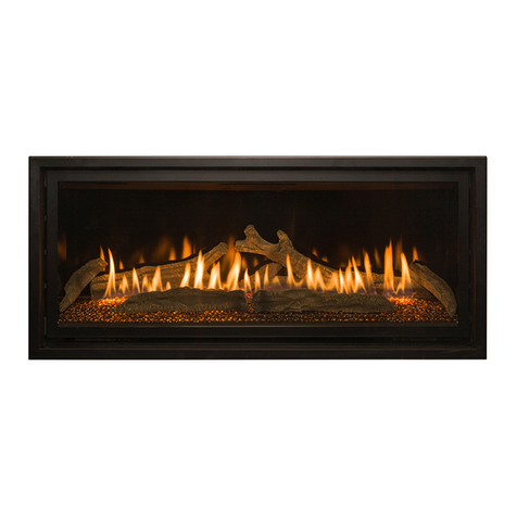
Trimline 70 SLInstallation instructions 14
9 CONCENTRIC FLUE SYSTEM
Theconcentricuesystemiscomposedofaninnerueand
anouterue.Theseueshavebeensetupconcentricallyso
thecombustiongaseswillbedischargedviatheinternalue
while the fresh combustion air is supplied via the gap between
theinnerandouterues.
9.1 Components of the concentric
uesystem
Differentconnectionsarepossibleusingtheconcentricue
system. These are:
Through the roof face and through the exterior wall
The pathway used for this system can be laid in different ways,
but there are a few important conditions:
• Thetotalallowedverticaluelengthmustnotexceed
9metres(thesumoftheuelengthandcalculationlengths
for the bends).
•90° bends have a 2-metre horizontal calculation length.
•45° bends have a 1-metre horizontal calculation length.
•The outlet can be installed at any point on the roof face or
exterior wall (supply and discharge in an identical pressure
area), but must meet applicable regulations.
•Flue pathways must not be insulated.
NOTE
Ensure the restriction plate is mounted in the correct
manner, as indicated in these instructions.
The correct restriction plate will provide the unit with the
mostoptimalefciency,ameimageandcombustion.
Mountinganincorrectlyplacedrestrictionplatemaycause
malfunction of the unit.
9.2 Indirect/direct façade connection
ifapplicable
See Chapter 8
The outlet may also be installed above the exhaust in the
wall, taking any hindrance to the surrounding area into
consideration, in accordance with national, regional, local
standards and regulations.
NOTE
Ensure wind pressure on the outlet is not excessive,
suchasinlocationswithabalcony,atroof,cornersand
very narrow alleys, etc., as this can negatively affect the
performance of the unit.
• Makearecessinthefaçadeofaround155mmwhen
usingØ100-150ues(keepanextraspaceof50mmin
arefractoryfaçadearoundtheoutertube)andtthefaçade
pass-through with the wall plate on the inside of the wall.
The wall plate of the exterior façade pass-through must be
sealedsufcientlyagainstthewallontheoutsidetoavoid
moistureand/oruegasleaksleakingintothelivingspace.
We recommend our clearance box use as a direct façade
pass-through through a refractory façade.
• Theueshouldbeencasedifnecessary.Eveniftheue
istobeinstalledalongnon-refractorymaterials,sufcient
re-resistantmeasuresmustbetaken.
•Determine the position of the unit and outlet and begin
constructionoftheuewiththeconnectiononthe
unit, paying attention to the direction of installation and
connecting the elements by means of clamp strips.
• Thettedpipecanbeusedbetweenthebendsorwhen
connecting to the unit. If necessary, use wall brackets
tosupporttheue.
Mounting using the roof pass-through option
• Theueoutletcanbelocatedatanyrandomplaceonthe
roof face (supply and exhaust in identical pressure areas)
and must meet the applicable rules and regulations.
• Aroongsheetforaatrooforaroongsheetleadfor
slopingtiledroofscanbeusedforawatertightduct.Use
various bends for the slope, if required. The recess in the
roof decking should be 5cm larger all around to ensure
sufcientreresistance.
•One needs to take into account the regulation regarding
reresistancebetweenrooms(Seenational,regional,local
standardsandregulations).Acasingofreproofmaterial
(forexample,12mmPromatectre-resistantplate)should
beappliedupto25mmfromtheouterue.
•Determine the position of the unit and the outlet and begin
theconstructionoftheuewiththeconnectionontheunit
(always1metreverticalrst)payattentiontothedirection
ofinstallation.Theinneruemustbeinstalledfordraining
purposes. Connect the elements using the clamping straps.
Ensure all connections are gastight.
• Attedpipecanbeusedbetweenthebendsorwhenmaking
theconnectiontotheunitand/ortheroofpass-through.Use
2wallbracketstosupporttheueoneachoor.
9.3 Installation instructions regarding
existing ues
See Appendix 2
Instructions
Theuegasexhaustsystemfallswithincategory:C91and
must be built in accordance with national rules and regulations
andtheinstructionsofthemanufacturer,asspeciedinthe
documentation and installation instructions.
This means, among other things, that the chimney pass-
through must not be smaller than 150mm round/square,
butnolargerthan200mm,andnotventilatedbygrilles,etc.
Inthecaseoflargerchimneypass-throughs,aexiblehoseof
around150mmmaypossiblybeusedincombinationwitha
exiblehoseofaround100mm,asdescribedbelow.Forother
situations, consult your supplier/manufacturer.
9.4 Parts
Check all parts for damage before commencing the
installation.Fortheconversionofabrickuetoconcentric
ue,connectedtoCCuesystem,youneedthecomponents
described in Appendix 2.
NOTE
The renovation kit consists of parts:
4 Interiormountingplate
5 Slidingelement
8 Chimneymountingplate


