Vision PREMIUM DSP 10-300kVA Specification sheet

1
Operating and Installation
manual for
PREMIUM DSP
10-300kVA
Uninterruptible Power Systems

2
Important Notice
Thank you for purchasing VISION UPS.
This document provides instructions about safety, installation and handling of the UPS. It is necessary to
read the manual completely before working on this equipment.
Read the manual completely before working on this equipment!
Keep this manual near UPS for easy consultation!
Symbols
This symbol points out the instructions which are especially important.
This symbol points out the risk of electric shock if the following instruction is not obeyed.
This symbol points out the instructions, which may be resulted with the injury of the operator or
damage of the equipment if not obeyed.

3
Index
1Safety ...................................................................................................................................................... 5
2Installation ............................................................................................................................................. 6
2nd1 Transportation ...................................................................................................................................................................6
2nd2 Unpacking...........................................................................................................................................................................6
2nd3 Storage.................................................................................................................................................................................6
2nd4 Placement ...........................................................................................................................................................................6
2nd4.1 Environmental Requisites .......................................................................................................................................6
2nd4.2 Electrical Requisites..................................................................................................................................................7
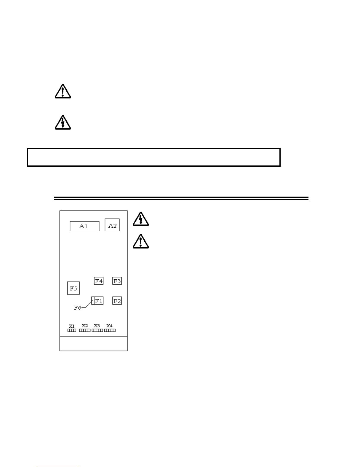
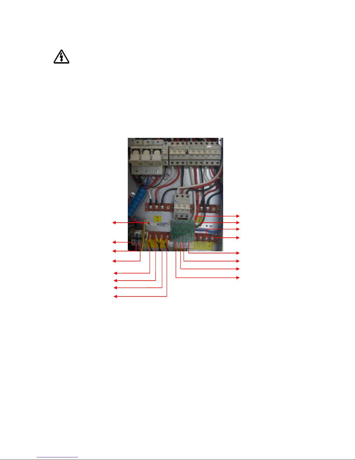
2nd5 Connections .......................................................................................................................................................................8
2nd5.1 Power Connections ..................................................................................................................................................9
2nd5.1.1 Protective Earth (Ground) Connections ............................................................................................................... 12
2nd5.1.2 Input Connection ....................................................................................................................................................... 13
2nd5.1.3 Separated by-pass mains input connection (optional) ........................................................................................ 13
2nd5.1.4 External Battery Connection.................................................................................................................................... 13
2nd5.1.5 Output Connection.................................................................................................................................................... 14
2nd5.2 Communication Interface Connections..............................................................................................................14
3Modes of Operation ..............................................................................................................................15
3rd1 Bypass Mode ....................................................................................................................................................................16
3rd2 Normal Mode ..................................................................................................................................................................17
3rd3 Battery Mode....................................................................................................................................................................17
4Control and Monitoring ........................................................................................................................18
4th1 Front Panel.......................................................................................................................................................................18
4th1.1 Keypad......................................................................................................................................................................18
4th1.2 Mimic Panel .............................................................................................................................................................19
4th1.3 Liquid Crystal Display (LCD) and User Menu..................................................................................................20
4th1.4 Buzzer .......................................................................................................................................................................23
5Operating Procedures .......................................................................................................................... 24
5th1 Commissioning................................................................................................................................................................24
5th2 Decommissioning ...........................................................................................................................................................24
5th3 Switching into manual by-pass during operation ......................................................................................................25
5th4 Returning from manual bypass to UPS.......................................................................................................................25
5th5 Connection to a generator .............................................................................................................................................25
6Operating Procedures for Parallel Systems .......................................................................................... 26
6th1 Introduction .....................................................................................................................................................................26
6th2 Procedure for Commissioning and Start Up ( First Installation ) ..........................................................................26
6th3 Procedure for Transferring to Static Bypass ..............................................................................................................29
6th4 Procedure for Transferring to ( Maintenance ) Manual Bypass..............................................................................29
6th5 Procedure for Switching OFF ......................................................................................................................................29
7Features and operating limits .............................................................................................................. 30
7th1 Mains limits for normal operation ...............................................................................................................................30
7th2 By-pass mains limits for bypass operation..................................................................................................................30
7th3 Battery test........................................................................................................................................................................30
7th4 Overload behavior ..........................................................................................................................................................31
7th5 Electronic short circuit protection...............................................................................................................................31
8Communication ................................................................................................................................... 32
8th1 RS232 Communication ..................................................................................................................................................32
8th2 RS422 Communication ..................................................................................................................................................32

4
8th3 Digital Inputs (UPS OFF and GEN ON)..................................................................................................................33
8th4 Free Contact Communication ......................................................................................................................................33
9Maintenance......................................................................................................................................... 35
9th1 Battery fuses.....................................................................................................................................................................35
9th2 Batteries ............................................................................................................................................................................35
9th3 Fans ...................................................................................................................................................................................35
9th4 Capacitors .........................................................................................................................................................................35
10 Troubleshooting................................................................................................................................... 36
11 Technical Specifications ...................................................................................................................... 39

5
1Safety
Information related to the safety of the UPS, loads and the user is summarized below.
But the equipment should not be installed before reading the manual completely.
The equipment may only be installed and commissioned by authorized technical persons.
When the UPS is brought from a cold place to a warmer place, humidity of the air may
condensate in it. In this case, wait for two hours before beginning with the installation.
Even with no connections have been done, hazardous voltages may exist on connection terminals
and inside the UPS. Do not touch these parts.
Connect the PE ground connector before connecting any other cable.
Do not put the battery fuses into the fuse holder before operating the equipment and seeing the
“NORMAL” message on the LCD.
The connections shall be made with cables of appropriate cross-section in order to prevent the
risk of fire. All cables shall be of insulated type and shall not be laid out on the walking path of
the persons.
Do not expose UPS to rain or liquids in general. Do not introduce any solid objects.
The equipment shall be operated in an environment, which is specified in “placement” section of
this manual.
Affix a label bearing the following expression, on the distribution panels feeding the UPS :
“Isolate the Uninterruptible Power Supply before working on this circuit”
Do not plug the communication cables in or out during stormy weather.
The equipment shall only be maintained and fixed by authorized technical persons.
In case of an extraordinary situation (damaged cabin or connections, penetration of foreign
materials into the cabin etc.) deenergize the UPS immediately and consult to the technical service.
Replaced batteries must be disposed of at authorized waste disposal centers.
Keep this manual near for easy consultation.
The equipment shall be packed properly during transportation.
The equipment is compliant with the European Community directives. Hence it is marked:

6
2Installation
2nd1 Transportation
The UPS must remain in a vertical position throughout the transportation.
Make sure that the floor can support the weight of the system.
2nd2 Unpacking
Equipment and batteries whose packages are damaged during transportation shall be inspected by
a qualified technical person before starting with the installation.
The procedure is as following:
Remove the bands and the protective packaging from the UPS.
Use suitable equipment to remove the UPS from the pallet.
Mount the cabinet parts supplied with the UPS after positioning and connecting the UPS.
The equipment shall be packed properly during transportation. Therefore it is recommended to
keep the original package for feature need.
Check if the following are provided with the equipment
Key of the cabin door
Battery fuses (three pieces)
Test report
2nd3 Storage
Recommended storage temperature, humidity and altitude values are listed on the “Technical
specifications” section.
If the batteries will be stored for longer than 2 months, they shall be charged periodically. Charge period
depends on the storage temperature. The relationship is as shown below:
Every 9 months if the temperature is below 20 C,
Every 6 months if the temperature is between 20 C and 30 C,
Every 3 months if the temperature is between 30 C and 40 C,
Every 2 months if the temperature is over 40 C
2nd4 Placement
2nd4.1 Environmental Requisites
This product meets the safety requirements for devices to be operated in restricted access locations
according to EN 60950-1 safety standard, which states that the owner should guarantee the following:
Access to the equipment can only be gained by service persons or by users who have been
instructed about the reasons for the restrictions applied to the location and about any precautions
that shall be taken and,

7
Access is through the use of a tool or lock and key, or other means of security and is controlled
by the authority responsible for the location.
Recommended operating temperature, humidity and altitude values are listed on the “Technical
specifications” section. Air conditioning may be required to provide these values.
Other requisites are:
The equipment and the batteries shall not be exposed to direct sunlight or placed near to a heat
source.
Do not expose UPS to rain or liquids in general. Do not introduce any solid objects.
Avoid dusty environments or areas where dust of conductive or corrosive materials is present.
Air outlets of the UPS are on sides, front and back except 80kva ups. At 80kva the FANs are on
the tope side of the ups therefore there are no air inlets, outlets at the rear panel at 80kva. Leave
at least 75 cm at the front and both sides and 50 cm at the back for maintenance and ventilation.
At 80kva you do not have to leave any space at the rear part.
2nd4.2 Electrical Requisites
The installation must comply with national installation regulations.
The electrical distribution panels for the mains and separated by-pass mains inputs must have a protection
and disconnection system. Disconnection devices used in these panels shall disconnect all line conductors
and the neutral conductor simultaneously. The following table shows the recommended size of the mains
and separate by-pass mains input protection devices (thermal, magnetic and differential) and the cable
cross-sections for the linear loads.
UPS
Input
thermal
protection
Bypass
mains input
thermal
protection
Input cable
cross-
section
Bypass
mains input
cable
cross-
section
Battery
cable cross-
section
Neutral
Cable
Cross
section
Leakage
current
protection*
10 kVA (1Ph output)
25 A
50 A
6 mm2
6 mm2
6 mm2
10 mm2
30 mA
10 kVA (3Ph output)
25 A
25 A
6 mm2
6 mm2
6 mm2
10 mm2
30 mA
15 kVA (1Ph output)
25 A
80 A
6 mm2
6 mm2
6 mm2
10 mm2
30 mA
15 kVA (3Ph output)
25 A
25 A
6 mm2
6 mm2
6 mm2
10 mm2
30 mA
20 kVA (1Ph output)
40 A
100 A
10 mm2
25 mm2
10 mm2
25 mm2
30 mA
20 kVA (3Ph output)
40 A
40 A
10 mm2
10 mm2
10 mm2
16 mm2
30 mA
30 kVA (1Ph output)
63 A
160 A
16 mm2
35 mm2
16 mm2
35 mm2
30 mA
30 kVA (3Ph output)
63 A
63 A
16 mm2
16 mm2
16 mm2
25 mm2
30 mA
40 kVA (3Ph output)
80 A
80 A
16 mm2
16 mm2
16 mm2
25 mm2
30 mA
60 kVA (3Ph output)
100 A
100 A
25 mm2
25 mm2
25 mm2
35 mm2
30 mA
80 kVA (3Ph output)
125 A
125 A
35 mm2
35 mm2
35 mm2
50 mm2
30 mA
100 kVA (3Ph output)
160 A
160 A
35 mm2
35 mm2
35 mm2
50 mm2
30 mA
120 kVA (3Ph output)
200 A
200 A
50 mm2
50 mm2
50 mm2
70 mm2
30 mA
160 kVA (3Ph output)
250 A
250 A
70 mm2
70 mm2
70 mm2
95 mm2
30 mA
200 kVA (3Ph output)
315 A
315 A
95 mm2
95 mm2
95 mm2
120 mm2
30 mA
250 kVA (3Ph output)
400 A
400 A
120 mm2
120 mm2
120 mm2
150 mm2
30 mA
300 kVA (3Ph output)
500 A
500 A
150 mm2
150 mm2
150 mm2
185 mm2
30 mA
Input magnetic protection devices shall have D characteristic.

8
*Load leakage currents are added to those generated by the UPS. If loads with high leakage currents are
present, adjust this value accordingly. It is recommended to adjust the protective device after measuring
the total leakage current with the UPS installed and operational with the intended load.
During transitory phases (power failure, return and voltage fluctuations) short leakage current peaks may
occur. Make sure that the protection is not activated in such cases.
If the loads have a nonlinear characteristic, the current on the mains input, separate by-pass
mains input and output neutral conductors may have a value that is 1.5-2 times the phase value
during operation. In this case, size the neutral cables and the input/output protection adequately.
According to EN 62040-1-2, the user shall place a warning label on the input distribution panel
and the other primary power isolators, in order to prevent the risk of electric shock caused by a
fault voltage on the UPS. The label shall carry the following wording:
Isolate uninterruptible power supply before working on this circuit
2nd5 Connections
Connections shall be done by authorized technical staff only.
When the UPS is brought from a cold place to a warmer place,
humidity of the air may condensate in it. In this case, wait for
two hours before beginning with the installation.
Layout of the connection terminals and boards are shown below:
A1: Communication interface board
A2: Parallel connection board (optional)
F1: Input circuit breaker
F2: Output circuit breaker
F3: Manual by-pass circuit breaker
F4: By-pass circuit breaker (optional)
F5: Battery circuit breaker
F6: Inrush fuse
X1: Battery terminals
X2: Input mains terminals
X3: Separate by-pass mains terminals (optional)
X4: Output terminals

9
2nd5.1 Power Connections
Devices with internal batteries may have dangerous voltages on the battery terminals
The power screw terminals are located on the lower front side of the UPS. Terminal details for 3ph
output ups’s and for 1phase output ups’s are shown separately in the below figures. Refer to the names of
each terminal to identify it during connection:
10-15-20-30kVA (3ph-3ph) UPS Terminal Connections
BATTERY (-)
BATTERY NEUTRAL
BATTERY (+)
PE
INPUT L1
INPUT L2
INPUT L3
INPUT NEUTRAL
OUTPUT L1
OUTPUT L2
OUTPUT L3
OUTPUT NEUTRAL
SPLITT-BYPASS NEUTRAL
SPLITT BYPASS L3
SPLITT BYPASS L2
SPLITT BYPASS L1

10
10-15-20-30kVA (3ph-1ph) UPS Terminal Connections
40-60kVA UPS Terminal Connections
80-100kVA UPS Terminal Connections
PE
BATTERY (-)
BATTERY NEUTRAL
BATTERY (+)
INPUT L1
INPUT L2
INPUT L3
INPUT NEUTRAL
SPLITT BYPASS NEUTRAL
SPLITT BYPASS L3
SPLITT BYPASS L2
SPLITT BYPASS L1
OUTPUT NEUTRAL
OUTPUT L3
OUTPUT L2
OUTPUT L1
PE
BATTERY (-)
BATTERY NEUTRAL
BATTERY (+)
INPUT L1
INPUT NEUTRAL
OUTPUT L1
OUTPUT NEUTRAL
SPLITT BYPASS NEUTRAL
SPLITT BYPASS L1
INPUT L2
INPUT L3

11
120-160-200 UPS Terminal Connections
PE
BATTERY (-)
BATTERY NEUTRAL
BATTERY (+)
INPUT L1
INPUT NEUTRAL
INPUT L2
INPUT L3
OUTPUT NEUTRAL
OUTPUT L3
SPLITT BYPASS NEUTRAL
SPLITT BYPASS L3
OUTPUT L2
OUTPUT L1
SPLITT BYPASS L2
SPLITT BYPASS L1
OUTPUT NEUTRAL
OUTPUT L3
OUTPUT L2
OUTPUT L1
SPLITT BYPASS NEUTRAL
SPLITT BYPASS L3
PE
BATTERY (-)
BATTERY NEUTRAL
BATTERY (+)
INPUT L1
INPUT NEUTRAL
INPUT L2
INPUT L3
SPLITT BYPASS L2
SPLITT BYPASS L1

12
250-300kVA UPS Terminal Connections
Cables shall be passed through the hole under the connection terminals.
Make sure that all circuit breakers are “OFF”/”0” before starting with the installation.
Connections shall be done with the order below.
2nd5.1.1
Protective Earth (Ground) Connections
The device shall be earthed for a safe and reliable operation. Connect the PE ground connectors
before connecting any other cable
Input protective earth connection terminal (PE) of the UPS shall be connected to ground with a low
impedance connection.
PE terminals of the loads shall be connected to output protective earth terminal of the UPS.
If there is an external battery cabin present, it shall be grounded via battery protective earth terminal of
the UPS.
INPUT & OUTPUT
NEUTRAL
PE
BATTERY (-)
BATTERY N
BATTERY (+)
INPUT L1
INPUT L3
OUTPUT L3
OUTPUT L2
OUTPUT L1
INPUT L2

13
2nd5.1.2
Input Connection
Bring the circuit breaker on the distribution panel to “OFF” or “0” position before making the
connections
Connect the phases to input (X2) L1, L2 and L3 terminals.
A definite phase sequence is needed for the UPS to operate. If you encounter “IN SEQ FLR” alarm at
start up, decommission the UPS, make the protection devices on the input distribution panels “0”/”OFF”
and interchange any two phase cable.
Connect neutral to N terminal of X2.
2nd5.1.3
Separated by-pass mains input connection (optional)
Bring the circuit breaker on the distribution panel to “OFF” or “0” position before making the
connections
Connect the phases to bypass (X3) L1, L2 and L3 terminals.
Make sure that the phases have the same sequence with the input supply.
Connect neutral to N terminal of X3.
2nd5.1.4
External Battery Connection
Do not put the battery fuses into the fuse holder (F5) before operating the equipment and seeing
the “NORMAL” message on the LCD.
Devices with internal batteries may have dangerous voltages on the battery terminals
To connect external batteries, do the following:
Switch the circuit breaker of the external batteries to “OFF” or “0” position.
Connect the (-) pole of the external batteries to the battery (-) terminal,
Connect the (+) pole of the external batteries to the battery (+) terminal,
Connect the midpoint of the external batteries to the battery N terminal.
Danger of explosion and fire if the batteries of the wrong type are used.

14
2nd5.1.5
Output Connection
To enable the short circuit protection feature of the UPS, each load shall be fed over a separate
circuit breaker chosen according to the load current. This may provide quick disconnection of the
short circuited load and operation continuity of the other loads. To obtain maximum protection,
the rating of each individual load circuit breaker shall have the minimum value, which is enough
to carry the full load current continuously.
Rated apparent and active power of the loads shall be less than the UPS power ratings.
Connect the loads to output (X4) Line and N terminals.
2nd5.2 Communication Interface Connections
Related information is given in “communication” section.

15
3Modes of Operation
There are three operation modes, which differ in the path of the energy flow.
UPS block diagrams and the energy flow path in each operation mode is shown below:
When UPS has no separate bypass mains input, bypass line is also fed from the mains input. Thus, if such
a device is in question, mains input shall be comprehended when the bypass mains input is referred in the
following sections of the manual.
UPS behavior at the start-up is different from the usual operation. The UPS can only operate in bypass
mode during start-up. So, in order for the UPS to start-up, frequency/waveform/rms value of the bypass
mains voltage shall be in acceptable limits and bypass shall be enabled.

16
After start-up, the following applies:
Operation mode depends on the priority, inverter, rectifier and bypass preferences made by the user and
mains, separate by-pass mains and battery voltages.
Priority and inverter, rectifier and bypass preferences can be set by using the COMMANDS and extra
commands (EXTCMNDS) menus.
If operation in any of these modes is impossible, output voltage will not be present. In this case, loads will
not be fed, and “VSECFLR” message is shown on the LCD instead of operation mode.
3rd1 Bypass Mode
Devices without separate bypass mains input, absorb energy from the mains. In devices with separate
bypass mains input, energy is drawn from the separate bypass mains.
Loads are fed via static bypass line.
Output voltage has the same amplitude, frequency and waveform as the input voltage.
Current drawn by the loads are only limited by the thermal/magnetic switches over the energy flow path.
Voltage, frequency and waveform of the bypass supply shall be in their tolerance limits, and bypass shall
be enabled for the UPS to operate in this mode.
When the upper provisions are met, the UPS works in bypass mode in the following conditions:
During the start-up
If the bypass priority is selected
If the inverter is disabled or blocked
In case of a prolonged overload
You can save energy by selecting the bypass priority. Efficiency in bypass mode is higher than the
efficiency in normal mode. If the bypass priority is selected, the UPS will operate in bypass mode
whenever the frequency/waveform/rms value of bypass mains voltage is in their tolerance limits. If the
bypass voltage goes beyond these limits, the UPS switches into normal operation.
Bypass mode doesn’t provide perfect stability in frequency/waveform/rms value of the output
voltage like in normal mode. Thus, the use of this mode should be carefully executed according to
the level of protection required by the application.
Bypass mode doesn’t provide electronic short circuit protection like in normal mode. If a short
circuit or occurs on the output during bypass operation, the thermal/magnetic protection will act
and all loads will be deenergized.
Prolonged overloads may cause the thermal/magnetic protection act. In this case, all loads will be
deenergized.

17
3rd2 Normal Mode
Energy is drawn from the mains input.
Loads are fed via the rectifier and the inverter. The AC voltage at the input is converted to a DC voltage
by the rectifier. The inverter converts this DC voltage to an AC voltage with a stable sinusoidal waveform,
amplitude and frequency.
Output voltage is sinusoidal and has a regulated amplitude and frequency. It is independent from the input
voltage.
The inverter is synchronized in frequency with the bypass mains input to enable load transfer to the
bypass supply without any interruption, in case of an overload or inverter failure.
Voltage and frequency of the mains input shall be in their tolerance limits, and both the rectifier and the
inverter shall be enabled for the UPS to operate in this mode.
When the upper provisions are met, the UPS works in normal mode in the following conditions:
If the inverter priority is selected.
If the bypass priority is selected but bypass is disabled or frequency/waveform/rms value of
bypass mains voltage is not in acceptable limits.
3rd3 Battery Mode
Energy is drawn from the batteries. Loads are fed via the inverter.
Output voltage is sinusoidal and has a regulated amplitude and frequency. It is independent from the
battery voltage.
Battery voltage shall be in acceptable limits and the inverter shall be enabled for the UPS to operate in this
mode.
When the upper provisions are met, the UPS works in battery mode in the following conditions:
If rectifier is disabled.
If the rectifier is disabled or frequency/waveform/rms value of mains voltage is not in acceptable
limits.

18
4Control and Monitoring
4th1 Front Panel
The front panel located on the upper part of the UPS informs the user about operating status, alarm
conditions and measurements. It also provides access to controls and configuration parameters.
Front panel shown below consists of three parts. As mimic panel provides basic information about the
energy flow path and existing alarms, LCD (liquid crystal display) offers detailed information and provides
access to controls. Keypad enables the user to move in the menu and to make selections.
4th1.1 Keypad
Functions of the buttons are given below:
BUTTON
SYMBOL
DEFINITION
ESC
Exit from the current menu
UP
Scrolls the available menus/values upwards. It increases the
value each time it is pushed when changing a parameter.
DOWN
Scrolls the available menus/values downwards. It decreases the
value each time it is pushed when changing a parameter.
ENTER
Enters the menu displayed on the screen. It makes selections or
confirms the choice/changes made.

19
4th1.2 Mimic Panel
Mimic panel is a diagram, which shows the path of energy flow in the UPS by means of several LED’s.
Definitions of LED states are shown below:
LED's
ID
COLOR
DEFINITION
STATE
Line 1
Green
Input mains voltage is OK and rectifier is active
Steady
Input mains voltage is OK and rectifier is inactive
Flashing
Input mains voltage is very close to its upper/lower limit and rectifier is
active
Input mains voltage is not OK
Off
Line 2
Green
Bypass voltage is OK
Steady
Bypass voltage is not OK and output voltage is synchronized to the
bypass voltage
Flashing
Bypass mains voltage is not OK and output voltage is not synchronized
to the bypass voltage
Off
Battery
Red
Battery mode is active and battery voltage is OK
Steady
UPS is performing battery test and battery voltage is OK
Battery mode is active and battery voltage is close to its lower limit
(energy available in the battery is about to be depleted)
Flashing
Battery test is active and battery voltage is close to its lower limit
(energy available in the battery is about to be depleted)
Rectifier is active and able to supply whole power required by the
inverter
Off
Inverter
Green
Load is fed via inverter
Steady
Inverter is not active
Off
Load
Green
Load is powered
Steady
Load is powered but UPS is overloaded
Flashing
Output voltage is not OK
Off
Bypass
Yellow
Load is fed via static bypass line
Steady
Bypass is not active
Off
Fault
Red
No alarms
Off
A minor alarm is present
Flashing
A major alarm is present
Steady

20
4th1.3 Liquid Crystal Display (LCD) and User Menu
LCD provides detailed information about device status, alarms and measurements. It also enables the
operator to manage the UPS. All information, commands and configuration parameters are given in a
menu, which has the following structure:
LCD consists of two lines and has the following structure:
“OPERATING MODE” or “VSECFLR”
“MENU or PARAMETER NAME”
If there is no voltage on the output, VSECFLR message is displayed on the upper line.
Operation mode parameter is one of the notations below:
OPERATING MODE NOTATIONS
NORMAL
Normal mode
BYPASS
Bypass mode
BATT
Battery mode
Menu and parameter descriptions are given below:
ALARMS MENU
ALR
=
“XXXXXXXXXXXX”
12 digit service codes.
Note these numbers before referring technical service.
ST
=
“XXXX-XXXXXXXX”
Alarm codes and names can be seen by entering the ALR submenu.
This manual suits for next models
13
Table of contents
Other Vision UPS manuals
Popular UPS manuals by other brands

socomec
socomec Masterys BC Installation and operating manual

Eaton
Eaton 93E UPS Installation and operation manual

LEGRAND
LEGRAND Trimod HE user manual

Powerware
Powerware 9315 installation manual

Powervar
Powervar Security Plus User instruction manual

Eaton
Eaton Power Xpert 9395 550 Installation and operation manual

Huawei
Huawei UPS5000-E-400K-SM user manual

Toshiba
Toshiba UT1A1A010C6 user guide

Velleman
Velleman UPS400N manual

Alpha Outback Energy
Alpha Outback Energy Tri Power X33 HE user manual

Alpha Technologies
Alpha Technologies CFR 3000 Operator's manual

Fideltronik Inigo
Fideltronik Inigo KI 1000R 1U user manual