Vision SPIRIT II G User manual

User Manual
Vision Spirit II G
6-10KVA
PF0.9 –1/1 phase
True online double conversion UPS

SPIRIT II G 6-10KVA PF0.9 LCD - UPS www.visionups.com
- 2 -
All rights reserved.
The information in this document is subject to change without notice.
Thank you for purchasing this series UPS.
This series UPS is an intelligent, single phase in single phase out, high frequency online UPS
designed by our R&D team who is with years of designing experiences on UPS. With excellent
electrical performance, perfect intelligent monitoring and network functions, smart appearance,
complying with EMC and safety standards, The UPS has become standard product meets the
world’s advanced level.
Read this manual carefully before installation. This manual provides technical support to the
operator of the equipment.

SPIRIT II G 6-10KVA PF0.9 LCD - UPS www.visionups.com
- 3 -
Safety Instruction
1. Prohibition
1.1 There is a high risk of electric shock from the UPS inside, so please do not open or
remove the casing or front panel unless it is operated by authorized technicians,
otherwise warranty becomes void as well.
1.2 Please contact and discuss with distributors before connecting the UPS to following
equipments
Medical equipments which have direct relationship with patients’ life
Equipments like elevators which may do harm to human being
Similar equipments as mentioned above
1.3 Don’t dispose of the battery with fire so as to avoid explosion
2. Safety notice
1) Output of standard UPS configured with internal batteries may be energized even if
the UPS input is not connected to the utility
2) Do disconnect the UPS input and make sure the UPS is complete off before moving
the UPS or reconfigured the connection, otherwise there will be potential electric
shock.
3) For the sake of human being safety, please well earth the UPS before starting it.
4) Working environment and storage way will affect the lifetime and reliability of the
UPS. Avoid letting the UPS work under following environment for long time
Area where the humidity and temperature is beyond the specified range
(temperature 0 to 40 Celsius degree, relative humidity 5%-95%).
Direct sunlight and location nearby heat
Area which can be crashed easily
Area with corrosive gas, flammable gas, excessive dust, etc.
5) Keep the ventilations in good conditions otherwise the temperature of components
inside UPS will be high and the component and UPS life will be affected.
6) It is forbidden to pour liquid or put any objects into the UPS.
7) Don’t use liquid extinguisher if there is a fire, a dry powder extinguisher is
recommended.

SPIRIT II G 6-10KVA PF0.9 LCD - UPS www.visionups.com
- 4 -
8) Battery life cycle will be shorter as environment temperature rise. Replacing battery
periodically can help to keep UPS in normal status and assure backup time required.
Battery replacement should be done by authorized technician.
9) Keep the UPS in a dry area or environment if it will not be free of operation for long
time. Storage temperature of UPS with internal battery is -20℃~+55℃, extended
backup model without internal battery is -40℃~+70℃.
10) Taking out the UPS or batteries from storage, it is recommended to connect them
with the utility for at least 12 hours per 3 months to avoid battery over-draining
11) Don’t open the battery, electrolyte inside will do harm to eyes and skin. Please use
plenty of clean water to wash if touching and go to see a doctor

SPIRIT II G 6-10KVA PF0.9 LCD - UPS www.visionups.com
- 5 -
Contents
1. Production Introduction ........................................................................................................... - 7 -
1.1 Application............................................................................................................................... - 7 -
1.2 Product range......................................................................................................................... - 7 -
1.3 Systme principle diagram...................................................................................................... - 7 -
1.4 Features .................................................................................................................................. - 8 -
1.5 Product overview.................................................................................................................... - 8 -
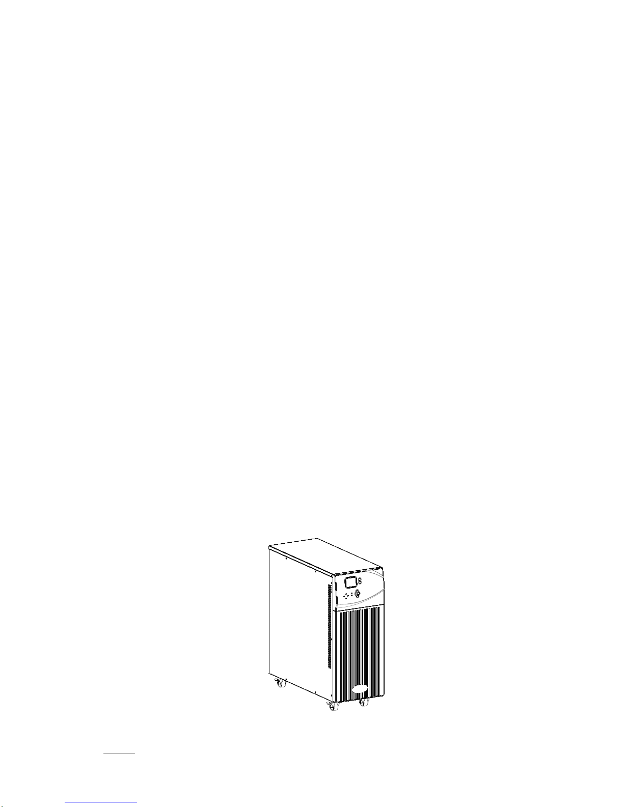
1.5.1 Product view.................................................................................................................... - 8 -
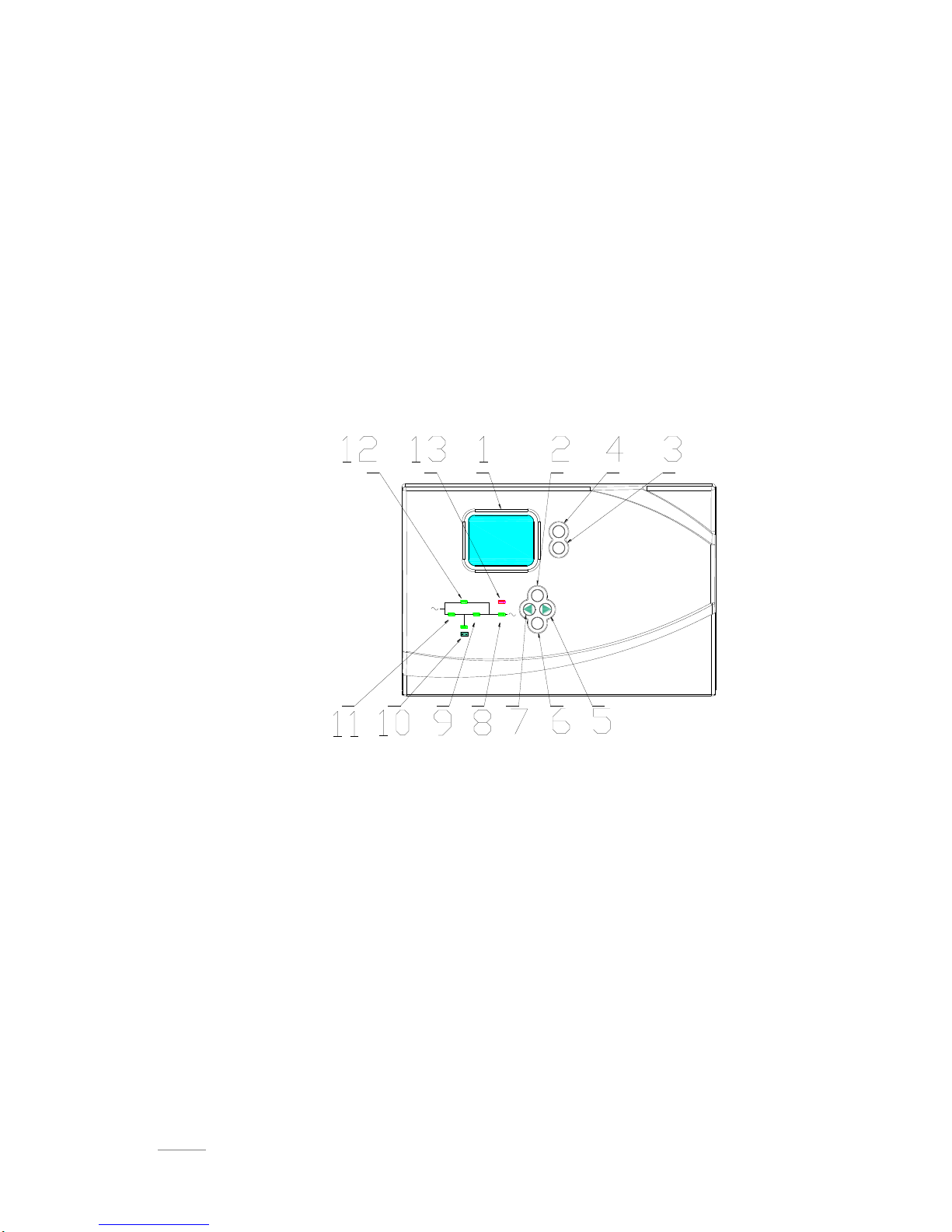
1.5.2 LCD Operation instruction............................................................................................. - 9 -
1.5.3 Display instruction ........................................................................................................ - 11 -
1.5.4 Rear panel instruction.................................................................................................. - 13 -
2 Installation................................................................................................................................... - 15 -
2.1 Unpack checking.................................................................................................................. - 15 -
2.2 Installation procedure.......................................................................................................... - 15 -
2.2.1 Installation note............................................................................................................. - 15 -
2.2.2 Installation...................................................................................................................... - 16 -
2.3 Connection of parallel system............................................................................................ - 18 -
3.Operation..................................................................................................................................... - 19 -
3.1 Working modes .................................................................................................................... - 19 -
3.1.1 AC mode........................................................................................................................ - 19 -
3.1.2 Bypass mode................................................................................................................. - 19 -
3.1.3 Battery mode................................................................................................................. - 19 -
3.1.4 ECO mode..................................................................................................................... - 20 -
3.2 Operation ............................................................................................................................. - 20 -
3.2.1 Power on........................................................................................................................ - 20 -
3.2.2 System parameter setting ........................................................................................... - 20 -
3.2.3 Start................................................................................................................................ - 20 -
3.2.4 Inverter shutdown......................................................................................................... - 21 -
3.2.5 Power off........................................................................................................................ - 21 -
3.3 Working Mode and transferring.......................................................................................... - 21 -
3.3.1 Transfer to bypass if overload .................................................................................... - 22 -
3.3.2 Normal mode to battery mode.................................................................................... - 22 -
3.3.3 Go to Bypass mode due to over temperature .......................................................... - 22 -
3.3.4 Output short circuit ....................................................................................................... - 22 -
3.4 UPS monitoring.................................................................................................................... - 23 -
3.5 LCD operation menu ........................................................................................................... - 23 -
3.5.1 Main menu switching.................................................................................................... - 23 -
3.5.2 Submenu switching...................................................................................................... - 23 -
3.5.3 Priority of info displayed on LCD ............................................................................... - 23 -

SPIRIT II G 6-10KVA PF0.9 LCD - UPS www.visionups.com
- 6 -
4 Maintenance................................................................................................................................ - 24 -
4.1 Fan maintenance ................................................................................................................. - 24 -
4.2 Battery maintenance............................................................................................................ - 24 -
4.3 Visual checking .................................................................................................................... - 24 -
4.4 UPS status checking ........................................................................................................... - 25 -
4.5 Function checking................................................................................................................ - 25 -
5 Trouble shooting....................................................................................................................... - 25 -
Appendix 1. USB communication ............................................................................................ - 27 -
Appendix 2. RS232 communication port definition............................................................. - 28 -
Appendix 3. Specification........................................................................................................... - 29 -
Appendix 4. Option ...................................................................................................................... - 31 -
Appendix 5. UPS message table............................................................................................... - 31 -

SPIRIT II G 6-10KVA PF0.9 LCD - UPS www.visionups.com
- 7 -
1Production Introduction
1.1 Application
This series UPS providing reliable AC power to various equipment, can be used for
computer center, network management center, auto control system, telecom
systems, etc
1.2 Product range
Capacity
6kVA
10kVA
Model
6kVA S
6 kVA H
10kVA S
10kVA H
Remarks
with internal
battery
External battery
with internal
battery
External battery
1.3 System principle diagram
The system can work in single unit, and parallel so as to enhance the reliability.
Fig.1-1 Single unit

SPIRIT II G 6-10KVA PF0.9 LCD - UPS www.visionups.com
- 8 -
1.4 Features
This series UPS is newly introduced. It is an intelligent online sine wave UPS.
High frequency, double conversion, high input power factor, wide input voltage
range, the output will not be disturbed by power network, suitable for area with
poor power supply condition
DSP technology for all-digital control, high reliability, self-diagnostics and
protections are featured
Intelligent battery management which extends battery life
LCD panel and LED indicators clearly indicate the system status and
parameters such as input/output voltage, frequency , load ,temperature inside
UPS, etc.
Perfect network power management can be achieved by using UPS
monitoring software
Maintenance bypass switch is provided so the power supply to load will not be
interrupted during repair
Friendly maintenance module design, easy for maintenance.
1.5 Product overview
1.5.1 Product view
F1-2 Complete unit view

SPIRIT II G 6-10KVA PF0.9 LCD - UPS www.visionups.com
- 9 -
1.5.2 LCD Operation instruction
The LCD control panel which consists of LCD display board, LED and buttons, (see
Fig1-3) displays and controls these information including operating information, alarm
information, function setting information.
LCD control panel
1) Five green LED and one red LED
2) LCD control panel which can display four line of English
3) Button: On, Off, ESC, Enter, and Left, Right
ON
OFF
ESC
ENT
BYPASS
RECT INV OUTPUT
FAULT
Fig.1-3 LCD control panel introduction
1. LCD Display Board
2. ESC
3. Off button
4. On button
5. right or down
6. Enter/Save
7. left or up
8. Output Indicator
9. Inverter Indicator
10. Battery Indicator
11. Mains (AC) Indicator
12. Bypass Indicator
13. Fault Indicator

SPIRIT II G 6-10KVA PF0.9 LCD - UPS www.visionups.com
- 9 -
LED indicator definition
1) Fault Indicator(red):On indicates when a fault occurred; Off means no fault
2) Indicator(Green):On means AC is normal, Off means AC is not present,
blinking means voltage is beyond normal range
3) Inverter Indicator(Green):On : when load is powered by inverter, Off : when it
is not working, blinking: when overload
4) Bypass Indicator(Green):On : when UPS is in bypass mode, Off: not in bypass
mode; blinking: when the input is beyond normal range
5) Battery Indicator(Green):On: when UPS is in battery mode, Off : Not in Battery
mode; Blinking: when battery voltage is low or battery is not connected
6) Output Indicator(Green):On: when there is output, Off: no output.
LCD display content
1) Running parameters
Input voltage/frequency, output voltage/frequency/current/loading, output power,
inverter voltage, battery voltage/battery remaining capacity, Bus voltage/bus
running time, temperature inside UPS
2)Alarm information (priority from high to low)
It provides shutting down, auxiliary power fault, output short circuit, inverter fault,
rectifier fault, over temperature, overload, charger fault, battery fault, battery
capacity low, ready to shut down and output fault.
3)Parameter setting
Menu setting, working mode setting, battery capacity setting, ID of parallel UPS,
output voltage/frequency level, bypass voltage range, Buzzer enable
Boosting charging voltage 2.30 to 2.35V per cell, floating charging voltage
2.20 to 2.29V per cell(use PC to setting)
Battery capacity setting includes the Ah of each battery unit, battery quantity
16 to 20, parallel group number
Parallel setting
UPS ID setting
UPS amount setting

SPIRIT II G 6-10KVA PF0.9 LCD - UPS www.visionups.com
- 10 -
Button definition
Button
Definition
ON
Switch on the inverter by pressing and holding it for
1s when the UPS is off
OFF
Switch off the inverter output by pressing and holding
it for 1s when the UPS is on, load will be powered by
bypass output if the bypass is normal
ENT
Confirm the operation
ESC
cancel and go to previous menu
◀
Turn to another menu or parameter
▶
Turn to another menu or parameter
UPS Messages reference table
Explanation
Content / Message
Initialization
CurState: Init
No export
No-Out
At bypass
Bypass
Rectifier working
Mains
Battery mode
Battery
Battery testing
Testing
Starting
Starting
ECO mode
CurState : ECO
EPO mode
CurState: EPO
UPS maintaining
CurState: M-Byp
UPS fault
CurState: Fault
Battery float charging
Battery Charging
Battery Boost charging
Battery Boost
Inverter on/off
Inverter ON/ Inverter OFF
Master of UPS
Inver Master
Maintenance switch close or open
SWMB ON/ SWMB OFF

SPIRIT II G 6-10KVA PF0.9 LCD - UPS www.visionups.com
- 11 -
1.5.3 Display instruction
1) The main interface below comes out when the power is connected or the system is
cold start. See Fig1.
Fig.1:Main interface
2) Press ESC/ ◀or ▶button, it will change to the basic status interface , see
Fig2 below.
Fig.2:Basic status screen
3) Press the ENT button, it will change to main menu, see Fig3.
Fig.3:Main menu
4) An arrow icon will come out on the LCD when pressing the ENT, then the data info,
status info, setting info can be selected by pressing the right or left arrow button, and
checking the details by pressing
5) Select and confirm the data info to be viewed in detail. It contains the details of the
AC input/output, inverter, battery, BUS, parallel, temperature. See Fig 4 to 12 below.
Fig.4:MAIN INPUT INFO Fig.5:OUTPUT INFO Fig.6:OUTPUT INFO
10.0KVA
FIGURE
Battery :7AH
Vin:220V 50HZ
Vout:220V 50HZ
FIGUER
STATUS
SETTING
FIGURE
Mains
220.0V 50.0Hz
FIGURE
Output
220.0V 0.0A
50.0Hz Load: 0%
FIGURE
Output
0KW 0KVA

SPIRIT II G 6-10KVA PF0.9 LCD - UPS www.visionups.com
- 12 -
Fig.7:INVERTER INFO Fig.8:BATTERY INFO Fig.9 BATTERY INFO
Fig.10:BUS INFO
Fig.11:PARALLEL INFO
Fig.12:TEMPERATURE
INFO
6) Select and confirm the status info can view the details, including status information,
alarm information, code, power rating and version. See Fig 13 to 14
Fig.13:main menu Fig.14:main menu
7) Select and confirm setting menu, setting information will be displayed on the screen,
which includes user set, system set, parallel set, battery sett, revise set. See Fig 15
to 19
Fig.15:setting menu Fig.16:setting menu
Fig.17:setting menu Fig.18:setting menu
FIGURE
Invert
220.0V 50.0HZ
FIGURE
P Battery
0V 0.0A
0min 0%
FIGURE
N Battery
0V 0.0A
0min 0%
FIGURE
BUS
-370V +370V
CAP:0Hour
FIGURE
Parallel
ID: 1
P_Amount:0
STATUS
Code:11
Fault :0. 0.0.0
Model:10.0KVA
STATUS
Version
V03B05D002
SETTING
Mode:NOR
Batt num:16
Batt cap:7AH
SETTING
V-Level:220V
F-Level:50Hz
SETTING
V-upper 15%
V-lower -45%
FIGURE
Temperature℃
PFC:27 INV:27
ENV:27
SETTING
Buzzer:Enable

SPIRIT II G 6-10KVA PF0.9 LCD - UPS www.visionups.com
- 13 -
Fig.19:Parallel setting
1.5.4 Rear panel instruction
1.5.4.1 6k H/S rear panel
Fig.1-4 Rear Instruction
1. Parallel slot
2. Maintenance bypass switch (covered)
3. Intelligent slot
4. EPO
5. COM
6. USB
7. Input switch
8. Input/output/battery terminal(covered)
SETTING
Parallel set
ID 1
P-amount 2
P-Redund 0

SPIRIT II G 6-10KVA PF0.9 LCD - UPS www.visionups.com
- 14 -
1.5.4.2 10k H/S rear panel
1. Parallel slot
2. Maintenance bypass switch (covered)
3. Intelligent slot
4. EPO
5. COM
6. USB
7. Input switch
8. Input/output/battery terminal(covered)

SPIRIT II G 6-10KVA PF0.9 LCD - UPS www.visionups.com
- 15 -
2 Installation
2.1 Unpack checking
1) Don’t lean the UPS when moving it out from the packaging.
2) Check the appearance to see if the UPS is damaged during transportation, do
not switch on the UPS if any damaged is found and please contact the dealer.
3) Check the accessories according to the packing list and contact the dealer if
found any parts missing
2.2 Installation procedure
2.2.1 Installation note
* Put the UPS at flat place next to the equipment.
* Keep the UPS at least 20cm from wall or equipment or other object. Don’t block
the ventilation holes of the UPS located in the front panel and the bottom part, so as
to *keep the ventilation in good conditions, avoid temperature of components inside
getting high.
* Keep the UPS away from high temperature, water, flammable gas, corrosive gas,
dust, direct sunlight and explosive things .
* Don't lay the UPS outdoor.
* 63A circuit breaker is required at the input L-N for 6KVA UPS, while 100A for the
10KVA UPS.
* PDU is required to connect to the UPS output so as to weaken the affection
between loads.
* In order to fix the UPS, please lock its wheels by shifting the sheet on each wheel.
* RCD load like computer, linear load and small inductive load can be connected
with the UPS. Please contact dealer if other types of loads is required to be
connected with.
* For the sake of user and equipments, please betake correct power configuration.
Fig.2-1 Correct power configuration

SPIRIT II G 6-10KVA PF0.9 LCD - UPS www.visionups.com
- 16 -
2.2.2 Installation
External battery connection (for extend model only )
1) The breaker on battery cabinet should be off.
2) Connect battery with positive pole, common pole and negative pole to battery
connector (BAT+, BATN, BAT-), don’t reverse battery polarity.
3) Make sure battery quantity complies with the specs. Measure the voltage of
battery bank after finishing connection and the battery voltage should be around
192/216/240Vdc. measure positive and negative battery voltage should be
around 96/108/120Vdc。Don’t mix batteries with different capacity,
manufacturers and don’t mix brand new and old batteries, either.
CAUTION
It is recommended to connect or replace battery after switching off the
system; don’t reverse battery polarity when doing battery hot-swapping.

SPIRIT II G 6-10KVA PF0.9 LCD - UPS www.visionups.com
- 17 -
UPS input and output connection
Minimum 10AWG copper wires are required for the 6KVA, and 8AWG for 10KVA,
including input/output cables, battery cables.
1) Switch off all breakers before connecting cables
2) Remove the cover of the terminals, see Fig 2-2,following it to connect the cables
Fig.2-2I/O terminals connection
3) Connect the UPS output L, N, E to L, N, E of load via a PDU. Tighten the screws
and shelter the terminals
WARNING
!
Please connect the output Earth well before go for other operation
Connection of the UPS communication cables
1) USB cable provided in accessories can be used to connect the UPS with PC
2) Follow steps below to install SNMP (if purchased ):
A. Remove the cover of SNMP slot at UPS rear panel and keep it for further use.
B. Insert the SNMP card and tighten the screws
C. Connect the UPS with internet by network cable.
D. Refer to the SNMP manual provided to do SNMP setting
CAUTION
Terminators are required so as to ensure the connections are firm
Don’t reverse the input L and N
Don’t connect the UPS input to a wall outlet or the outlet will get burnt.

SPIRIT II G 6-10KVA PF0.9 LCD - UPS www.visionups.com
- 18 -
2.3 Connection of parallel system
Parallel
cable Parallel
cable
Parallel
cable
UPS1 UPS2 UPS4
UPS3
Fig.2-3 parallel system
Make sure all the breakers are off and no output at the UPS output.
Extended connecting cables in Parallel:
When the UPSes are connected in parallel, the copper wires required to connect
with each UPS is minimum 10AWG for the 6KVA and 8AWG for 10KVA, but the
main wire for linking all the UPS in parallel should be N* 10AWG or 8AWG (N refers
to the number of the UPS in parallel.)
Make sure the cables are as shorter as possible to reduce any possible noise
interference to data transfer.
CAUTION
Connect the L, N and E well
Configurate individual battery bank for each extend backup UPS in
parallel system. Also can be use common battery bank.

SPIRIT II G 6-10KVA PF0.9 LCD - UPS www.visionups.com
- 19 -
3. Operation
3.1 Working modes
The UPS has AC mode, bypass mode, battery mode and ECO mode
3.1.1 AC mode
If the AC input and load capacity are in normal ranges, the load will be powered by
inverter output, battery will be charged at the same time.AC and inverter indicators
on LCD control panel will be on (green).
3.1.2 Bypass mode
When the AC power is connected and the UPS has not been switched on, or the
UPS is overloaded after switching on the UPS, it will go to bypass mode. The Loads
will be powered by AC, battery will be charged, and the bypass indicator on the LCD
control panel will be on (green). But, if the bypass is beyond normal range or absent,
the UPS will not go to bypass mode and no power will be supplied to the loads.
3.1.3 Battery mode
In AC mode, if the AC is absent or beyond normal range, the rectifier and charger
will stop working, the loads will be powered by battery bank of which energy goes
through inverter circuit. The Inverter’s and battery’s indicators on LCD control panel
will be on (green) and the alarm will beep every 3 seconds.
In battery mode, if the battery voltage becomes low and reaches the setting value,
the system will give low battery voltage alarm, beep once every second and the LCD
will give low battery alarm, too.
CAUTION
Charge batteries for at least 8 hours when the UPS is used at the first
time as battery has self-discharge characteristics even though the
UPS has been fully charged by manufacturer before shipping.
CAUTION
Please note below if the UPS input power is provided by a generator
1) Don't switch on the loads before starting UPS. After the UPS
has been started and worked steadily, switch on the loads one
by one. Suggest that the total capacity of the loads should
lower than 30% of capacity of generator
2) It is suggested that the rating of generator should be 1.5-2
times of the capacity of the UPS.
Table of contents
Other Vision UPS manuals
Popular UPS manuals by other brands

Powertronix
Powertronix Mizar user manual

Uninterruptible Power Supplies
Uninterruptible Power Supplies PowerWAVE 9000 DPA Installation and operating guide

CyberPower
CyberPower AVR Series user manual

Always “On” UPS
Always “On” UPS GES-242NX-R Installation and operator's manual

Riello
Riello VST 2000 Installation and use manual

Effekta
Effekta OFFICE-RM 600 operating manual