manuals.online logo
Brands
  1. Home
  2. •
  3. Brands
  4. •
  5. Vaisala
  6. •
  7. Antenna
  8. •
  9. Vaisala RM32 User manual

Vaisala RM32 User manual

Other Vaisala Antenna manuals

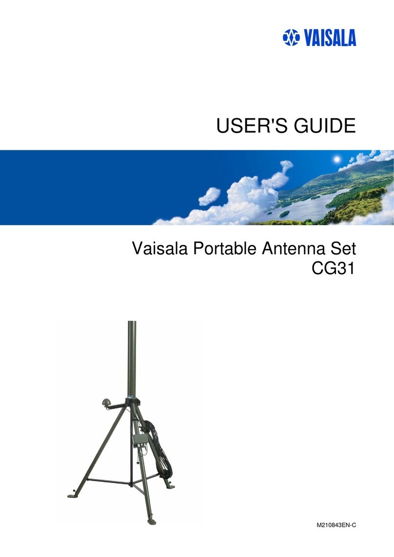
Vaisala CG31 User manual

Vaisala

Vaisala CG31 User manual

Vaisala CA31 User manual

Vaisala

Vaisala CA31 User manual

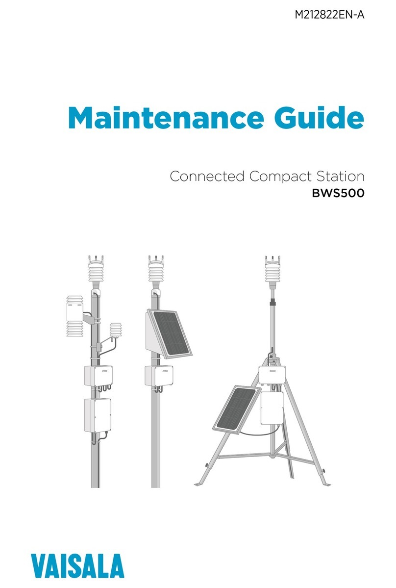
Vaisala Beacon Station BWS500 Operating manual

Vaisala

Vaisala Beacon Station BWS500 Operating manual

Vaisala RB31 User manual

Vaisala

Vaisala RB31 User manual

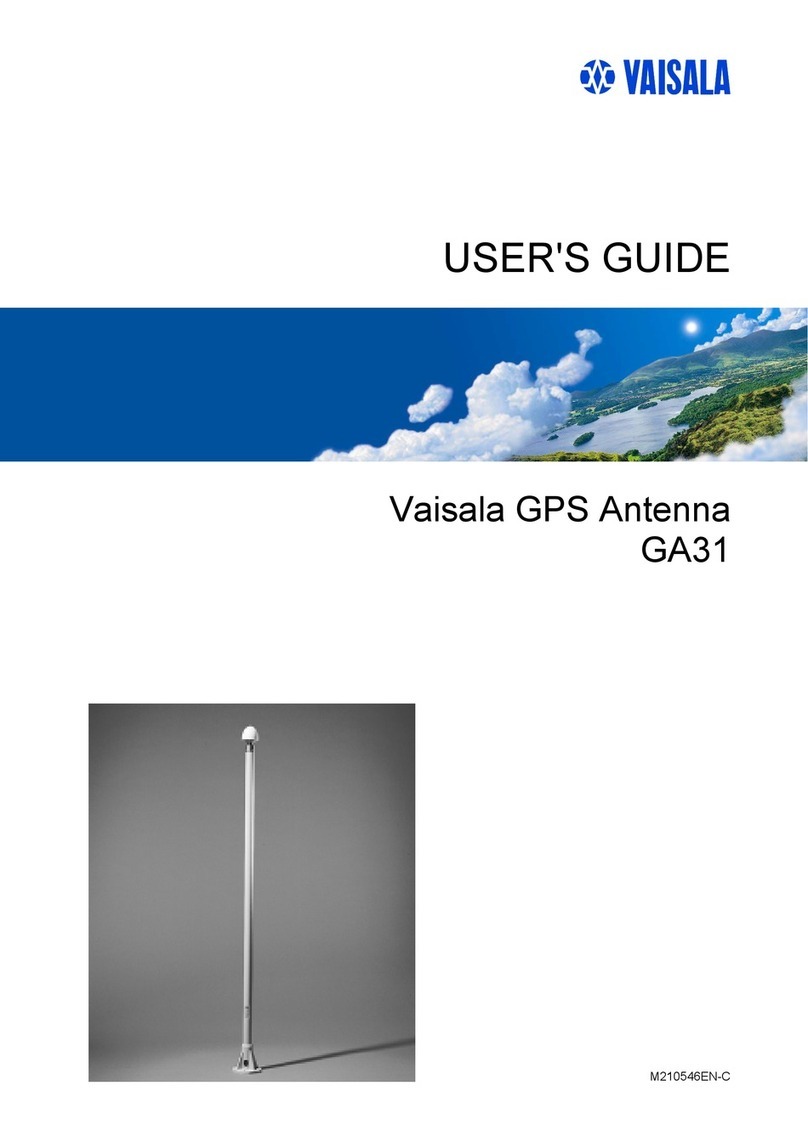
Vaisala GA31 User manual

Vaisala

Vaisala GA31 User manual

Popular Antenna manuals by other brands

DAVIS Windex AV 3160 installation instructions

DAVIS

DAVIS Windex AV 3160 installation instructions

Belden Hirschmann BAT-ANT-N-14G-IP23 Mounting instruction

Belden

Belden Hirschmann BAT-ANT-N-14G-IP23 Mounting instruction

Vtronix YHK Fitting instructions

Vtronix

Vtronix YHK Fitting instructions

KVH Industries TracVision 6 Technical manual

KVH Industries

KVH Industries TracVision 6 Technical manual

Leica Geosystems GS10 user manual

Leica Geosystems

Leica Geosystems GS10 user manual

Sirio Antenne Gain-Master manual

Sirio Antenne

Sirio Antenne Gain-Master manual

Sony VCA-41 Installation/connections

Sony

Sony VCA-41 Installation/connections

ZCG Y100 Series installation guide

ZCG

ZCG Y100 Series installation guide

Advantech Wireless INTREPID120 Assembly instructions

Advantech Wireless

Advantech Wireless INTREPID120 Assembly instructions

Cerio ANT-10AO installation guide

Cerio

Cerio ANT-10AO installation guide

Alfa Network APA-L01 Specifications

Alfa Network

Alfa Network APA-L01 Specifications

Naval PR-422CA Operation manual

Naval

Naval PR-422CA Operation manual

Feig Electronic ID ISC.ANTH200/200 Series manual

Feig Electronic

Feig Electronic ID ISC.ANTH200/200 Series manual

TERK Technologies TV44 owner's manual

TERK Technologies

TERK Technologies TV44 owner's manual

TERK Technologies SIR3 owner's manual

TERK Technologies

TERK Technologies SIR3 owner's manual

Directive Systems & Engineering DSE2324LYRMK quick start guide

Directive Systems & Engineering

Directive Systems & Engineering DSE2324LYRMK quick start guide

HP J8999A instructions

HP

HP J8999A instructions

MobilSat MSP-S Mounting instructions

MobilSat

MobilSat MSP-S Mounting instructions

manuals.online logo
manuals.online logoBrands
  • About & Mission
  • Contact us
  • Privacy Policy
  • Terms and Conditions

Copyright 2025 Manuals.Online. All Rights Reserved.

Quick Reference Guide
Vaisala Telemetry Antenna
RM32
0611-035
Figure 1 RM32 Antenna Assembly
PRODUCT OVERVIEW
This Quick Reference Guide yields a general description of the
Vaisala Telemetry Antenna RM32 used for receiving radiosonde
signals in the 400 MHz meteorological band.
General
Vaisala Telemetry Antenna RM32 is an antenna system intended
to be used with Vaisala DigiCORA® Sounding System. It is
well suited for fixed installations, but it can also be used in
portable systems where feasible.
RM32 has two antennas which have been selected to optimize
the performance in all elevation angles, both near the horizon
and at the zenith. The sounding system selects the antenna with
the best reception through a two position antenna switch.
Construction
The Vaisala Telemetry Antenna RM32 consists of
•vertical antenna (1)
•helix antenna (2)
•Antenna Amplifier and Switch RAA111G (3)
•tubular antenna mast, tube branch and antenna cables.
The numbering above refers to the figure on the cover page of
this Quick Reference Guide.
Vertical Antenna
The vertically polarized omnidirectional antenna performs best
at the low elevation angles when the radiosonde is near the
horizon. The maximum gain of 5dBi is just below zero elevation.
Helix Antenna
The helix antenna is an omnidirectional antenna with
approximately hemispheric coverage with a maximum gain of 3
dBic at the zenith.
Antenna Amplifier and Switch RAA111
All the amplifier parts are housed in a watertight box at the base
of the antenna mast. The amplifier runs on +12 VDC voltage,
supplied by the UHF receiver.
Antenna Mast and Tube Branch
The vertical antenna is installed on top of a tubular mast, and the
amplifier box is mounted on the base of the mast.
The helix antenna is attached to a flange in the tube branch.
A mounting sleeve is provided for mounting the whole antenna
on top of an external mast.
INSTALLATION
Select an installation site that is open, in other words, clear of
obstacles such as buildings, dense forests, or high metal masts.
1. Fit the Antenna Amplifier and Switch RAA111G on
the tubular mast.
2. Attach the tube branch to the tubular mast using the
clamp included as shown in Figure 2.
0611-037
Figure 2 Attaching the Tube Branch to the Tubular Mast
The distance between the antennas in the system is
optimized to minimize mutual interference. Set the
distance as shown in Figure 3.
0611-038
Figure 3 Distance Between the Vertical and Helix Antennas
3. Connect the vertical antenna with cables
(DRW214802) to the ANT1 and the helix antenna to
the ANT2 connector in the Antenna Amplifier and
Switch RAA111G. Direct the cables through the holes
in the antenna mast and the branch as shown in Figure
4.
4. Fit the vertical antenna on top of the tubular mast as
shown in Figure 4.
5. Fit the helix antenna on the flange of the tube branch
as shown in Figure 4.
www.vaisala.com Ref. M210814EN-A
0611-036
Figure 4 Connecting the Antennas
The following numbers refer to Figure 4 above:
6. Connect the feeder antenna cable (RARC13) to the
OUT connector of the RAA111G.
7. If you are mounting the whole antenna assembly on
top of an external mast, use the mounting sleeve of the
tubular antenna mast. The inner diameter of the sleeve
is 61.5 mm.
For instructions on connecting the antenna as a part of the
sounding system, see DigiCORA® Installation Manual.
WARNING
Always ensure that the antenna mast is connected to a
proper grounding point: a water conduit, a heating pipe or a
metal structure. Use separate cable for grounding if
necessary.
TECHNICAL DATA
Property Value
Vertical Antenna
Frequency range 400 - 406 MHz
Directivity 5 dBi
Polarization Vertical
Horizontal pattern Omnidirectional
Helix Antenna
Frequency range 400 - 406 MHz
Gain 3dBic
Polarization Right-hand circular
Horizontal pattern Omnidirectional
Telemetry Range
With RS92-SGP radiosonde 200 km
Amplifier
Gain 20 dB typical
Noise figure <2 dB
Power input +10 … 12 VDC, typically 130
mA through RF cable
Output impedance Output impedance 50 ohms,
VSWR <1.5
Mechanics
Cable connector Coaxial N-type male
Total height including mast 1760 mm
Inner diameter of mounting
sleeve
61.5 mm
Depth of mounting sleeve 200 mm
Distance between the
antennas
302 mm
Weight 11.4 kg with the feeder cable
6.3 kg without the cable
Standard cable length 33 m fixed
Environmental conditions
Operating temperature range -40 ... 55° C
Operating humidity range 0 … 100 % RH
Operating precipitation Unlimited
Maximum wind speed 65 m/s
Storage temperature -50 … +100 °C
Storage humidity 0 … 100 % RH
SPARE PARTS LIST
Part no. Item
212167 Vertical antenna, connector N-female
215809 Helix antenna, connector N-female
RAA111G Antenna Amplifier and Switch
DRW214802 Amplifier-to-antenna cable
RARC13 Antenna cable, 33m
1 = Holes in the antenna mast and branch
2 = Tubular mast
3 = Flange of the tube branch