Viso Systems LightSpion User manual

LightSpion
Patent pending
User guide
Last edited: 2013-03-27

© 2007 Viso Systems ApS, Denmark
All rights reserved. No part of this manual may be reproduced, in any form or by any means,
without permission in writing from Viso Systems ApS, Denmark.
Information subject to change without notice. Viso Systems ApS and all affiliated companies
disclaim liability for any injury, damage, direct or indirect loss, consequential or economic loss
or any other loss occasioned by the use of, inability to use or reliance on the information
contained in this manual.
Dimensions

3 LightSpion user guide
Contents
Introduction........................................................................ 6
About the LightSpion......................................................6
Package contents........................................................... 6
About this document.......................................................7
Installation ......................................................................... 8
Software installation.......................................................8
Connecting power ..........................................................9
Connecting USB........................................................... 10
Making measurements..................................................... 11
Alignment of light source.............................................. 11
Quality selection........................................................... 12
Full automatic............................................................... 13
Manual power control................................................... 15
Manual integration time setup....................................... 16
Free running spectrometer........................................... 17
Measurement data........................................................... 18
Power details................................................................ 21
CRI details.................................................................... 23
Attaching pictures......................................................... 25
Saving measurement ................................................... 26
Exporting to IES/LDT.................................................... 27
Exporting to PNG ......................................................... 28

4 LightSpion user guide
Exporting to CSV.......................................................... 29
Emailing measurement................................................. 30
Advanced setup............................................................... 31
Custom calibration........................................................ 31
Accuracy.......................................................................... 34
Photo spectrometer accuracy....................................... 34
Optical sensor accuracy............................................... 35
Circular field accuracy.................................................. 37
Lumen accuracy........................................................... 39
Specifications................................................................... 41

5 LightSpion user guide
Safety Information
Warning! This product is not for household use.
Read this manual before installing and operating the
controller, follow the safety precautions listed below, and
observe all warnings in this manual.
Preventing electric shocks
Always ground (earth) the power supply.
Use only a source of AC power that complies
with local building and electrical codes, and that
has both overload and ground-fault protection.
If the controller or power supply are in any way damaged,
defective, wet, or show signs of overheating, disconnect the
power supply from AC power and contact Viso Service for
assistance.
Do not install or use the device outdoors. Do not spray with
or immerse in water or any other liquid.
Do not remove any covers or attempt to repair the controller
or power supply. Refer any service to Viso.
Disposing of this product
Viso products are supplied in compliance with Directive
2002/96/EC of the European Parliament and of the Council of
the European Union on WEEE (Waste Electrical and
Electronic Equipment), as amended by Directive 2003/108/EC,
where applicable.
Help preserve the environment! Ensure that this product is
recycled at the end of its life. Your supplier can give details of
local arrangements for the disposal of Viso products.

6 LightSpion user guide
Introduction
About the LightSpion
The LightSpion is a revolutionary new portable lighting
measurement device making it possible for the first time to
measure all aspects of a light source within a few seconds.
Package contents
The LightSpion package contains the following items.
LightSpion portable measurement system
Light Inspector software CD-ROM
Viso calibration certification document
E27 goniometer base light holder
Light source alignment tool
E14, B22, GU10 from E27 socket converters
2 m IEC power cord
2 m USB cable

7 LightSpion user guide
About this document
This guide describes how to install and use the LightSpion
controller, and how to make measurement of different light
sources.

8 LightSpion user guide
Installation
Software installation
Before you can start using the LightSpion, the “Viso Light
Inspector”software must be installed. Supported on all
windows platforms.
Use the following link to download the latest version:
http://www.lightdataserver.com/software/Viso%20Systems/Viso
%20Light%20Inspector.msi
Please make sure the LightSpion is not connected to the
computer during software installation.
Run the msi file and follow the
installation instruction.
USB drivers are automatically
installed.
Your measurements are not
lost, when installing newer versions or uninstalling. All
measurements always remain in your document folder.

9 LightSpion user guide
Connecting power
The LightSpion comes with a standard IEC power in
connector and with standard euro power cable, but any
power cable can be used as the LightSpion support any
outlet voltage from 90-260VAC.
The power in connector supplies
power to the goniometer motor
and to the power analyser and
subsequent to the light source to
be measured, meaning that
power supplied will be identical to
power supplied to the light source
to be measured.
AC power supply cable plug
Warning: Risk of electric shock! Plug
installation shall be performed by a qualified
electrician.
A grounding-type (earthed) power plug that fits the local
power outlet must be used which you can acquire an IEC
power cable with a suitable grounding-type plug from most
consumer electronics stores.
When installing the plug connect pins as follows:
yellow and green wire to ground (earth)
blue wire to neutral
brown wire to live

10 LightSpion user guide
Connecting USB
The LightSpion is connected to the computer using a USB
connector type B. A 2m USB cable type A to B is included
with the LightSpion but any USB cable supporting USB2.0
can be used.
The USB supplies
communication and power to the
LightSpion’s main board
processor, power analyser and
photo spectrometer, meaning
that the photo spectrometer can
be used only with USB
connected.
After connecting USB start the “Viso Light Inspector”
software and connection to the LightSpion will automatically
be established. A successful
connection is shown with a green
“Connected” icon in the upper
right corner of the “Viso Light
Inspector” software.
USB can be connected and disconnected without the need
of restarting the “Viso Light Inspector” software, as
connection always is established automatically as soon as
the USB connector is plugged in and vice versa.

11 LightSpion user guide
Making measurements
Alignment of light source
Before making a measurement is it important to align the
light source to be measured. Use
the alignment tool located in the
front of the LightSpion and place it
in front of the light source.
Then adjust the height by sliding the
lamp holder bracket up and down.
Turn the lamp holder 90 degrees
and set the centre of rotation by
sliding the lamp forward and
backwards, so that the centre of the
illumination part of the lamp is
aligned with the alignment tool.

12 LightSpion user guide
When measuring light sources having narrow beam angles
is it important the light is pointing horizontally straight to
ensure that the centre of the beam is scanned at the correct
point as shown below.
After alignment turn the light source back pointing straight
towards the optical sensor.
Quality selection
Before making a measurement is it possible to select the
measurement quality by clicking on Setup->Measurement
quality.
As default does the “Viso Light Inspector” use the “low
resolution”. It is possible
to select 3 levels: low,
medium and high. Each
quality level increases
the number
measurements made during goniometer measurements and
also increases the photo spectrometer integration time
lowering noise level of photo spectrometer measurements.
Increasing the quality results in substantial extended
measurement time.

13 LightSpion user guide
Full automatic
By default does the “Viso Light Inspector” software make
full automatic measurement, meaning adjusting photo
spectrometer to the background light environment by
turning off the light source and measuring the background
light levels which subsequent is subtracted from
measurements so that measurements can be done even in
a lit room. The adjustment of the exposure time of the photo
spectrometer also known as integration time is also done
automatically.
A measurement is simply started by clicking on the
play icon.
Then is integration time automatically
set.
Then is the ambient light level
automatically measured by turning off
the light source.
The light source is then turned 180 degrees to prepare for
measurement.
Power is then measured and stored.

14 LightSpion user guide
Before detailed
auto re-scan
After detailed
auto re-scan
The complete 360 degrees angular
light field is then measured and the
beam angle is calculated.
Light sources having a narrow beam angle can result in the
number of measurements made in the beam section being
too few to generate an accurate measurement. In this case
will the “Viso Light Inspector” software automatically ask
you if you want to make a more detailed scan of the beam
section.
The increase in measurement quality after a detailed re-
scan of the narrow beam section can be seen below.

15 LightSpion user guide
When the measurement is complete is the total luminous
flux is calculated in lumen and CRI, lumen/watt, peak light
output in candela, power and power factor, is also
calculated.
Further details about the measurement data can be found in
the chapter “Measurement data”.
Manual power control
It can in some cases be necessary to control the light
source power manually. Such a case could be when
measuring a flash light which is powered using batteries
where the LightSpion’s power analyser is unable to turn on
and off the light source automatically. Another case could
be when measuring a low voltage light source such as LED
chips with external power supply that has a low response
time when turned on and off and therefore would give an
inaccurate result of the ambient
light level.
To enable manual power control
simply select Setup->Power
control and select manual power
control.
When manual power control has been selected will the
“Viso Light Inspector” ask you manually to turn on and off
the light source when necessary as shown below.

16 LightSpion user guide
Manual integration time setup
It can in some rear cases be desirable to setup the
integration time of the photo
spectrometer manually. One case
could be when measuring a light
source emitting most of the light to the
sides instead of in direction of centre.
As the automatic setup of integration
is done in the centre at 0 degrees
could the integration time be set to high, resulting in the
saturation of the photo spectrometer giving an inaccurate
measurement.
The integration time of the photo
spectrometer can be set manual
by selecting Setup->Integration
time.

17 LightSpion user guide
Free running spectrometer
The photo spectrometer can also be used as free running to
test different light sources that might be too large for a
complete goniometer measurement or just to have a real-
time update of how a light source behaves over time.
To start the photo spectrometer free run
simply click on the start spectra scan icon
During free run mode is light output in candela, CRI, and
colour temperature continuously updated.
The integration time can be changed during free run scan
as explained in previous chapter to ensure correct
resolution.
NOTE: After changing photo spectrometer integration time
should the spectra be “Calibrated to ambient light”.

18 LightSpion user guide
Measurement data
After a goniometer measurement is complete will the
following results be displayed.
1. The angular light distribution shows
the amount of light of the non-rotation
symmetrical part of the light source.
This field distribution is used to
calculate the beam angle.
2. The complete integrated spherical
spectra is shown in the spectra
window. Integrated spherical spectra
means that it is a spectra that is
created based on all the radiated
spectra’s in all angular direction
measured, this means that the
displayed spectra will be equal to that measured using an
integrating sphere.
3. The complete integrated spherical spectra calculated in
step 2 is used to calculate the complete
luminous flux in lumens.
The peak output in candela is also
displayed, which is the highest level of light output
measured during goniometer measurement.
4. The power is measured by sampling
voltage and current at a rate of 50.000
samples per second to ensure high
resolution and thus high power precision.

19 LightSpion user guide
The power factor (PF) which indicates the quality of power
consumption where 1.0 is the best normally achieved by a
pure resistive load such as a tungsten lamp and where 0.0
is the worst. The power factor (PF) value should be
between 1.0 - 0.5 to be within a satisfactory level. Please
refer to quality charter standards for different countries and
regions to acquirer power factor limits.
5. The efficiency in lumens per watt is calculated by dividing
lumens with power consumption. The result is display in the
efficiency bar where 100 lumen/watt
it displayed as most green. The
scientifically maximum value of 100% efficacy is 683
lumen/watt.
6. The CRI is calculated using 8 reflectance standard colors
to calculate the ability of the light to
reflect colors thus indicating the
quality of the light radiated. 0 being
the worst quality and 100 being the best quality equal to
that of the sun.
The CRI can only be used for white light, if CRI is not
displayed is indicating that the radiated light does not meet
the criteria for white light or that light levels are too low to be
measured.
7. The color temperature indicates the color of white light
and is displayed in kelvin. Where 6000K is observed as cold
and 2500K as warm. The kelvin
scale is derived from the temperature
of the tungsten filament thus explaining that high
temperature of the filament results in cold light and vice
versa. If color temperature is not displayed is indicating that

20 LightSpion user guide
the radiated light does not meet the criteria for white light or
that light levels are too low to be measured.
8. At maximized view is the color radiated shown as x,y
coordinates in a CIE1931 diagram. The CIE1931 diagram
illustrates all colors visible to the human eye, and is based
on experiment made in 1931 with a series of test persons to
find out how the human
eye observes colors.
The black line in
diagram is called the
black body curve and
illustrates all colors that
are defined as white
colors from warm to
cold. The point of the
measured color is shown with a black cross and can be
used to check the whiteness of a color, by checking how
close it is to the black body curve, the closer to the black
body curve the more accurate white is the color.
Other manuals for LightSpion
1
Table of contents
Other Viso Systems Measuring Instrument manuals
Viso Systems
Viso Systems LabSpion User manual

Viso Systems
Viso Systems LabSpion User manual
Viso Systems
Viso Systems BaseSpion User manual
Viso Systems
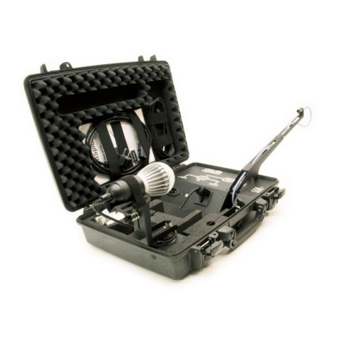
Viso Systems LightSpion LIGSP001 User manual

Viso Systems
Viso Systems LabSpion User manual

Viso Systems
Viso Systems LabFlicker User manual
Viso Systems
Viso Systems VISO SYSTEMS Labarazzi User manual
Popular Measuring Instrument manuals by other brands
Vortex
Vortex RWG Series user manual
VOLTCRAFT
VOLTCRAFT DT-70 operating instructions
Klein Tools
Klein Tools CL320 instruction manual

Nokeval
Nokeval Solid-Sky-2Pro-24VDC manual

Mountz
Mountz EZ-TORQ III operating instructions
Precision Digital Corporation
Precision Digital Corporation Helios PD2-6363 instruction manual
