Viso Systems LightSpion LIGSP001 User manual

VISO SYSTEMS LightSpion
User Manual
Revision: 3 September 2020

2
Congratulations on purchasing your new Viso Systems LightSpion. Before using this
product, please read the Safety Information.
This manual contains descriptions and troubleshooting necessary to install and
operate your new Viso Systems product. Please review this manual thoroughly to
ensure proper installation and operation.
For news, Q&A and support at Viso Systems, visit our website at
www.visosystems.com
Other manuals in this series for which the latest version can be downloaded from
www.visosystem.com, include:
▪Light Inspector User Guide (Software)
▪LabFlicker User Manual (optional equipment)
▪VISO Reference CALI-T50 User guide (optional calibration light source)

3
Contents
Safety Information........................................................................................................4
Preventing electric shocks ........................................................................................4
Disposing of this Product ..............................................................................................4
Introduction..................................................................................................................4
About this document ................................................................................................4
These guidelines describe the installation process of the LightSpion followed by
the typical measurements of various light sources...................................................4
About the LightSpion ................................................................................................4
Product Dimensions......................................................................................................5
Shipping packages.........................................................................................................5
Installation ....................................................................................................................5
Software installation.................................................................................................5
Connecting power.........................................................................................................6
AC power supply cable plug......................................................................................6
Connecting USB.............................................................................................................6
Room Considerations....................................................................................................7
Laboratory environment...........................................................................................7
Making measurements .................................................................................................7
Bulbs and Spots.........................................................................................................7
Strips and Tubes............................................................................................................9
LightPort Installation.................................................................................................9
Linear Light Holder Installation...............................................................................10
Check for light overspill...........................................................................................11
Advanced setup ..........................................................................................................12
Checking the calibration status...............................................................................12
Custom calibration..................................................................................................12
Accuracy......................................................................................................................15
Photo spectrometer accuracy.................................................................................15
Optical sensor accuracy ..........................................................................................15
Circular field accuracy.............................................................................................16
Specifications..............................................................................................................19
4
Safety Information
Warning! This product is not for household use.
Read this manual before installing and operating the LightSpion, follow the safety
warnings listed below, and study all the cautions in the manual.
Preventing electric shocks
Make sure the power supply is always grounded.
Use a source of AC power that complies with the local building and electrical codes,
that has both overload and ground-fault protection.
If the controller or the power supply are in any way damaged, defective, wet, or
show signs of overheating, disconnect the power supply from the AC power and
contact Viso Service for assistance.
Do not install or use the device outdoors. Do not spray with or immerse in water or
any other liquid.
Do not remove any covers or attempt to repair the controller or the power supply.
Refer any service to Viso.
Disposing of this Product
Viso Systems products are supplied in compliance with Directive 2012/19/EU on
waste - electrical and electronic equipment (WEEE) together with the RoHS Directive
2011/65/EU with amendments 2015/863. Help preserve the environment! Ensure
that this product is recycled at the end of its lifetime. Your supplier can give details of
local arrangements for the disposal of Viso Systems products.
Introduction
About this document
These guidelines describe the installation process of the LightSpion followed by the
typical measurements of various light sources.
About the LightSpion
The LightSpion is a portable far field goniometer system with a spectrometer sensor
that makes it possible to get all photometric measurements quickly and efficiently.
The Light Inspector software enables to quickly measure, save and export the newly
obtained data.
© 2007 Viso Systems ApS, Denmark
All rights reserved. No part of this manual may be reproduced, in any form or by any means,
without permission in writing from Viso Systems ApS, Denmark. Information subject to change
without notice. Viso Systems ApS and all affiliated companies disclaim liability for any injury,
damage, direct or indirect loss, consequential or economic loss or any other loss occasioned by
the use of, inability to use or reliance on the information contained in this manual.

5
Product Dimensions
Shipping packages
Shipping Dimensions
Shipping
Volume
Weight
1. LightSpion
450 x 350 x 160 mm
0.025 m3
(net 6 kg)
7 kg
Installation
Software installation
Before you can start using the LightSpion, the Viso Light Inspector software must be
installed. It is supported on all windows platforms.
Use the following link to download the latest version:
http://www.lightdataserver.com/software/Viso%20Systems/LightInspector.htm
Please make sure the LightSpion is not connected to the computer during software
installation.
Run the .msi file and follow the installation instruction.
USB drivers are automatically installed.

6
Your measurements are not lost when installing newer versions or uninstalling. All
measurements will always remain in your document folder. If you want to remove all
your measurements go to the ‘Light Inspector’ folder and delete them manually.
Typical folder location:
C:\Users\’Username’\Documents\Viso Systems\Light Inspector
Or if stored in dropbox:
C:\Users\’username’\Dropbox
Connecting power
The LightSpion comes with a standard IEC power-in connector and with a standard
euro power cable, but any power cable can be used as the LightSpion supports any
outlet voltage from 90-260VAC.
The power-in connector supplies power both to the goniometer motor and to the
power analyzer and then subsequently to the measured light source. It means that
the power is identical to the one of the measured light source (unless the latter is
power with an external power supply).
AC power supply cable plug
Warning: Risk of an electric shock! Plug installation shall be performed by a qualified
electrician.
A grounding-type (earthed) power plug that fits the local power outlet must be used.
You can acquire an IEC power cable with a suitable grounding-type plug from most of
consumer electronics stores.
When installing the plug connect pins as follows:
•Blue wire to neutral
•Yellow and green wire to grounding (earth)
•Brown wire to live
Connecting USB
The LightSpion is connected to the computer using a USB connector type B.
A 2 m USB cable type A to B is included in the LightSpion case, however any USB
cable supporting USB2.0 can be used.
The USB provides communication and power to the LightSpion’s main board
processor, power analyzer and photo spectrometer, meaning that the photo
spectrometer can be used only with the connected USB.
Start the Viso Light Inspector software after having connected the USB; the
connection to the LightSpion will be established automatically. A successful
connection is shown with a green “Connected” icon in the upper right corner of the
Viso Light Inspector software.
You can connect and disconnect the USB without restarting the Viso Light Inspector
software, as the connection is always established automatically as soon as the USB
connector is plugged in and vice versa.
Neutral
Ground/Earth
Live

7
Room Considerations
Laboratory environment
▪The LightSpion can be used outside of the laboratory and compensates
automatically for steady ambient light. However, for the most precise
measurements, a dark room/laboratory is recommended. You can find
guidance in
▪Always keep your laboratory clean from dust and particles. Dust may
interfere with measurement if it accumulates on and around the sensor by
introducing straylight and disturbing translucence. Dust and particles in the
mechanical parts of the goniometer may disturb functionality and may
cause wear on motors, belts and bearings. Disconnect all USB cables and
power supplies, and vacuum clean your goniometer regularly (normally
every month) to remove dust. Mount a brush on the vacuum cleaner
handle. Dry off all external surfaces with a clean, dry, cotton cloth (avoid
statics).
▪Avoiding air currents is necessary to minimize cooling of devices under
test. Limit air flow (e.g. from air conditioning systems or draught) around
the system (may alter light source intensity).
▪Limit heat transmission from light source through mounting system. Should
be mounted as realistically as possible
The standard test conditions and
tolerance intervals of CIE DIS 025
(laboratory conditions)
Standard test
condition
Tolerance interval
Ambient temperature
25.0 °C
±1.2 °C
Surface temperature for device
under test
Nominal operating
temperature tp
±2.5 °C
Air movement
Stationary air
0 m/s to 0.25 m/s
Making measurements
Bulbs and Spots
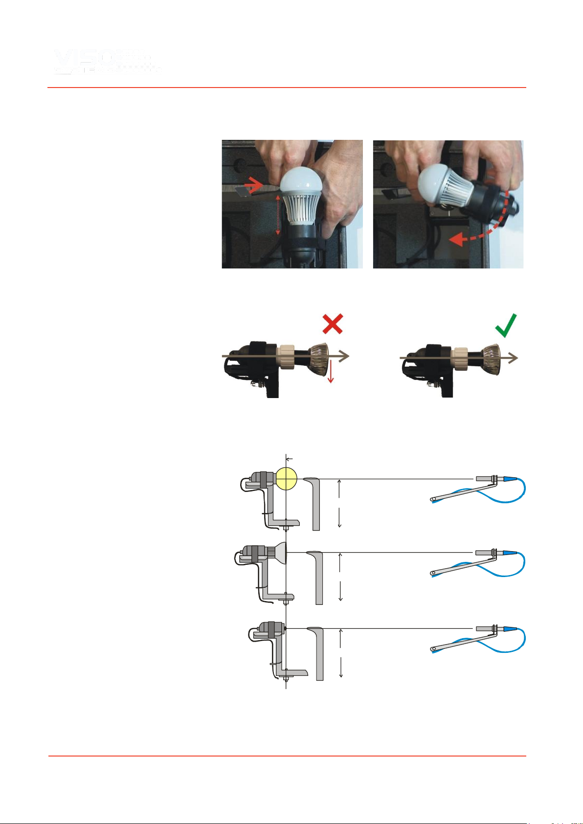
Before making any measurements, it is
important to align the investigated light
source. Use the alignment tool located in the
front compartment of the LightSpion case
and place it in front of the light source.
Then adjust the height by sliding the lamp
holder bracket up and down.
8
Turn the lamp holder 90 degrees and set the center of rotation by sliding the lamp
forward and backward, so that the center of the illumination part of the lamp is
aligned with the alignment tool.
When measuring light sources with narrow beam angles it is important to ensure
that the light is pointing straight horizontally to make certain that the centre of the
beam is scanned at the correct point as shown below.
After alignment turn the light source back pointing straight towards the optical
sensor.
Different alignment examples are shown below:
Center hight
Center hight
Center hight
Center of rotation
Light bulb
Spot light
LED chip

9
Strips and Tubes
The LightSpion can also measure linear light sources such as LED strips or tubes. The
width of the linear tubes cannot exceed half of the maximal diameter, which is 8 cm.
That means the maximum width of the linear tube is 4 cm.
To measure a linear light source a “light port bracket” can be used to ensure that
only a fixed portion of the linear light sources is being measured as shown below.
The “light port bracket” ensures that light from only 8 cm of the linear light source is
captured. The actual length of the light source is then typed into the software after
the measuring process is finished. An alternative to the bracket is to effective mask
off directly on the light source to ensure that only 8 cm contributes to the light
output.
Click Edit -> Photometric -> Linear sources to insert the real length of the source to
the software. The complete light output of the linear light sources is then calculated.
For linear light sources of flexible lengths such as LED strips it is also possible to get
the light output information specified in lumen per meter or foot.
NB: The bracket is not intended for use with “LightSpion Extender”.
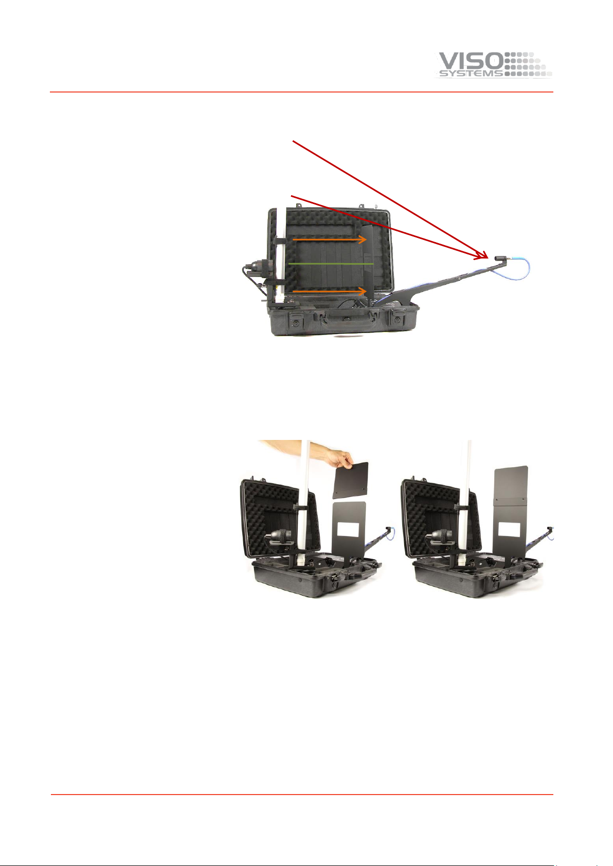
LightPort Installation
The “light port bracket” should be place in the LightSpion case to ensure the correct
measurement as shown below:
1) The LightPort is stored in the lid
2) Place the lid in the slot in front of the
arm
Linear light
holder
Light port
bracket
8 cm

10
3) A magnet keeps it in place
4) Push it in, to the end of the slot
Linear Light Holder Installation
The “linear light holder” is set and used as shown in the pictures below:
1) Take holder from the lid
2) Push to the end
3) Erect holder
4) Use Velcro straps to hold fixture
5) Center the light source
11
Check for light overspill
Light overspill, which is the light retrieved by the detector outside of the light port
bracket area, can increase the measured value of the luminous flux.
An extension plate for the light port bracket will prevent the light overspill. The
extension is smoothly attached on top of the port bracket as shown in the pictures
below.
Light
overspill
12
Advanced setup
Checking the calibration status
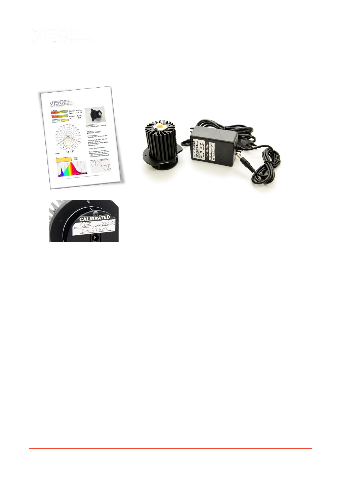
A special Viso reference light source (Reference 800) is included in the package. The
light source has its own power supply, and both parts are labelled with identical
calibration date and numbers. Never measure without the original power supply.
Right after factory calibration of your system, the refence light source was measured
and a certificate was issued. The certificate is part of the delivery. The certificate can
also be downloaded from Viso’s website using the calibration number on the labels.
With the reference lamp you can quickly check your calibration status:
•Check whether the total flux in lumen and peak candela is close to the
original values
•Check whether the shape of the spectrum is close to the original shape.
•Check whether the spectrum looks spiky or jagged.
If you are not happy with the result, the system needs to be calibrated. Viso
recommends calibration every year, or minimum every 2 years. Viso provides
calibration service, or you may do your own calibrations following the ‘Custom
Calibration’procedure.
Check-up Procedure
•Place the Reference 800 with the indicator (the oblong hole in the base)
upwards
•Do not preheat the light source before measurement
•Centre the light source in the gonio (measuring distance 66 cm)
•Start measurement normal measurement. In the stabilization window,
choose “1,0% in 15 min.” and let the measurement finish by itself.
Custom calibration
The LightSpion is delivered in a pre-calibrated condition. It is also possible to make a
custom calibration of the photo spectrometer if desired. This could be necessary if
the LightSpion is to be certified by an official agency, which will perform its own
calibration and afterwards issue certification documents.
To make a custom calibration a calibration source must be used, the spectrum of
which in a directional point at a certain distance is known. Such a spectrum is usually
specified as power in μW/cm2/nm, as shown below.
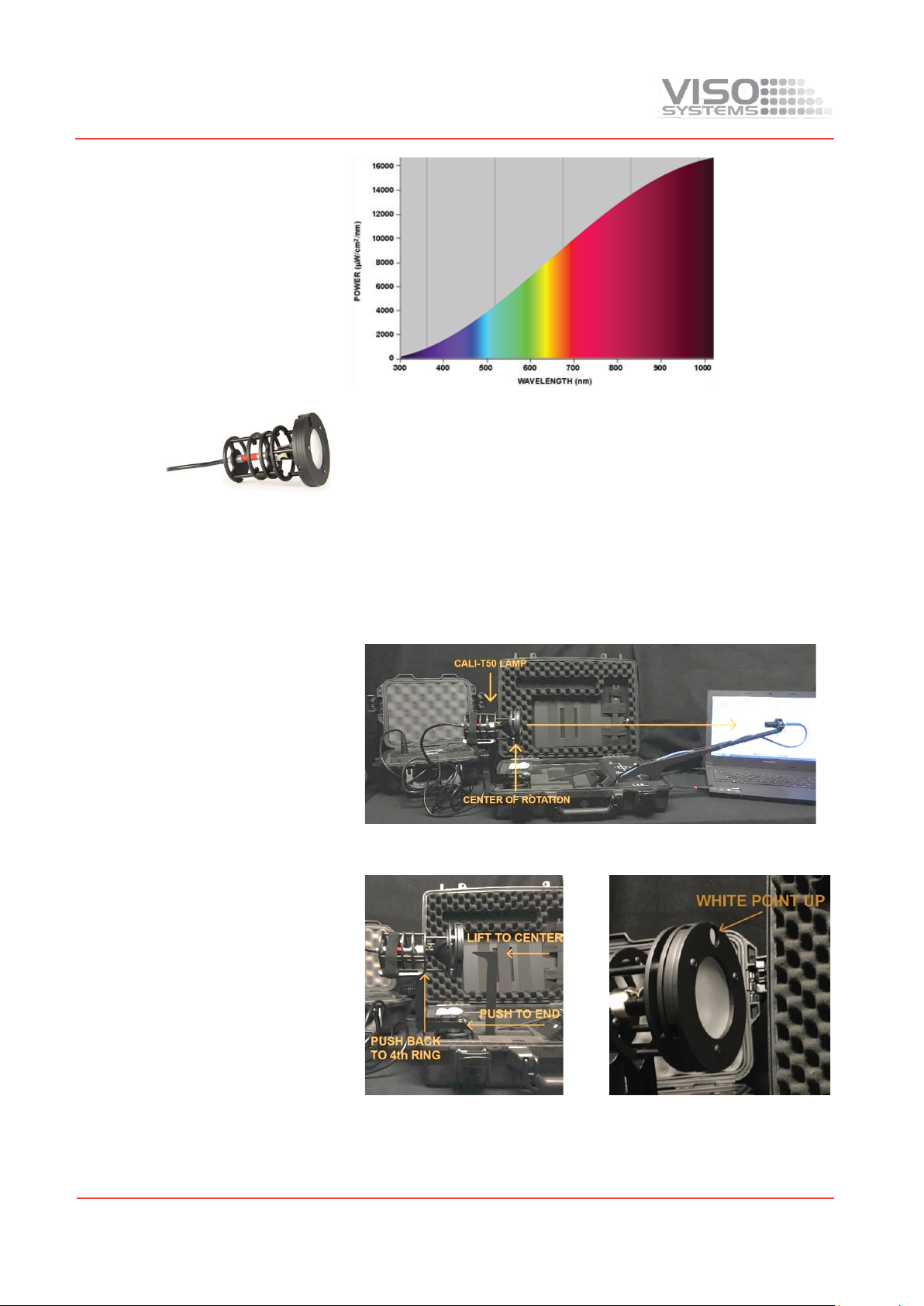
13
Calibration sources can be obtained from a number of suppliers, in this example will
we use the CALI-T50 from Viso Systems which is a tungsten irradiance lamp. The
spectrum of the calibration source is usually provided in a .lmp file (lamp file).
NOTE! Making a custom calibration does not delete the Viso factory calibration. You
can always switch between factory and custom calibration at any time.
IMPORTANT: Calibration must be made in a dark environment, with non-reflective
surfaces.
These steps show how to make a custom calibration.
1
Place the calibration lamp at the center of the rotation motor and make sure it is
lifted to the right height by using the alignment tool.
The lamp must be pointed directly towards the sensor. Sometime is might be
necessary to unplug RJ45 cable to the motor to enabling precise alignment

14
2
Open the Viso Light Inspector software
connected to the LightSpion via USB and
select Setup - Spectrometer calibration.
Then select custom calibration and click
on the new button. Note: The primary
factory calibration will not be lost, and
you can always return it.
3
Select “Load lamp file” to load the
calibration source spectrum. The system
will automatically calculate the intensity
of the source in candela based on the
lamp file at a distance of 0.5 m. If the
measurements are done at a different
distance, then click on the re-calculate
button. If you don’t know the lamp
distance but know the intensity value in
candela, simply insert it directly into the
candela box.
4
Make sure the calibration source has
been turned on for at least 30 min, so the
output is stable.
5
Click next and set the integration time to
a maximum possible value to ensure the
highest resolution, and therefore the best
calibration quality.

15
6
Click next and cover the sensor or turn off
the calibration source so the dark
reference spectra can be measured
7
Click next –and the calibration is then
finished.
When you close the calibration dialog will you be asked if you want to save the
calibration to the device. When selecting yes, the custom calibration will be saved
inside the device you can always switch back to the factory calibration at any time.
Accuracy
The accuracy of the LightSpion device consists of the sum of individual accuracies of
the involving parts as follows:
▪Photo spectrometer accuracy
▪Optical sensor accuracy
▪Circular field accuracy
The accuracies of these devices are described below.
Photo spectrometer accuracy
The spectrometer used in the LightSpion is Ocean Optics STS-VIS.
The accuracy of the spectrometer has been previously tested in a wide temperature
range from -10 to +50 degrees, therefore the device is adjusted for a temperature
drift.
The linearity of the photo spectrometer is corrected to have an error < +/- 0.5% from
15-95% full scale (2,500 –14,000 counts net).
The effect of the linearity error will also affect the color and CRI measurements so
the complete series of measurement errors are as follows:
▪Intensity error < +/- 0.5%
▪Color temperature error < +/- 35 Kelvin
▪CRI error < +/- 0.7%
Optical sensor accuracy
The accuracy of the sensor depends on a change of a sensitivity field as a function of
position (it is also called the sensitivity span). The measurement setup with an
indicated sensitivity span of less than 8.5% is presented below.

16
The system is constructed for measuring light sources with a maximum diameter of
100 mm. It is calibrated with the help of a calibration source with an aperture
diameter of 35 mm with constant field of light output. Thus, subsequently measured
light sources with the same aperture and a constant field will have an error of 0%,
whereas light sources smaller than 35 mm will have a positive error and vice versa.
The errors can occur due to differences in sizes of apertures of light fixtures. The
largest error is then calculated according to the minimum and a maximum aperture
sizes.
Max positive error +0.49% Max negative error -2.55%
In most cases the maximum error would be smaller than 2.55%, as the light radiated
from a large aperture would be highest in the center.
The inaccuracy of the sensor is rounded off to < +/- 2%.
Sensor intensity error < +/- 2%
Circular field accuracy
The LightSpion measures the luminous flux in lumen, which accounts for light
radiated in all directions. Lumen measurement is generally done with the help of an
integrating sphere, which allows to collect light radiated in all direction into one
point.
The LightSpion uses goniometer technology to obtain this measurement. It captures
light from one section of the light source and afterwards calculates the complete flux
value based on this section, as shown below (section “A” is presented in green).

17
The principle behind it is based on a consideration that the opposite field “B” is
circular (see in the picture above). Most of the light sources and fixtures have
nonuniform circular “A” and “B” fields.
In some particular cases the deviation from a circular uniformity of the “B” field is
caused by a physical geometry of the light source.
A series of test measurements of different types of light sources was made to account
for such errors.
The total flux accuracy is calculated for each type of light sources by summation of the
3 kinds of errors: Spectrometer Intensity Error + Sensor Error + Circular Field Error =
Total Lumen Accuracy
1.
A LED bulb with a frosted glass
cone.
For this type of light source the
“B” field is almost completely
circular and therefore it has a
small error when measured only
using the “A” field.
Accuracy = 0.5% + 2% + 1.6% < +/- 4.1%
2.
A LED bulb with a frosted
plastic cone.
The plastic cone exposes the
led. Thus it has a slightly
deviated distribution of the “B”
field, which results in a higher
error value
Accuracy = 0.5% + 2% + 2.3% < +/- 4.8%
3.
Fluorescent bulb with a frosted
cone.
The large field of light from a
fluorescent bulb and a
nonuniform wearing of the glass
tubes increase the error
compared to LED.
Accuracy = 0.5% + 2% + 4.6% < +/- 7.1%

18
4.
Fluorescent open bulb.
A non-frosted coned fluorescent
bulb exposes the glass tube
completely therefore producing
an oscillating “B” field, which
depends on the number of
tubes.
Accuracy = 0.5% + 2% + 7.9% < +/- 10.4%
5.
Incandescent clear glass.
Old-fashioned incandescent
bulb gives the largest error due
to a non-circular tungsten
thread.
Accuracy = 0.5% + 2% + 10.2% < +/- 12.7%
Based on the above, the average accuracy is then calculated as follows:
Total Average Lumen Error
= spectrometer intensity error + sensor error + (circular field error
type1 + type2 + type3 + type4+ type5) / 5
= 0.5% + 2% + (1.6% + 2.3% + 4.6% + 7.9% + 10.2%) / 5
= < +/- 7.82%

19
Specifications
Measurement method
Far Field, Type C
Physical Dimensions
Shipping dimensions (L x W x H)
(L x W x H) 46 x 17.5 x 37.5 cm
Shipping weight
6 kg
Dimensions (L x W x H)
43 x 11.5 x 33.5 cm
Weight
5 kg
Sensor distance
66 cm
Lamp diameter range
0 –80 mm
Lamp maximum weight
(tower in upright position)
4 kg
Electrical
Power supply input
90 - 260 VAC, 50/60 Hz
Power consumption
15 W
USB current consumption
200 mA
Power analyzer voltage range
30 VAC - 400 VAC <+/- 0.2V
Power analyzer current range
0 –3 A (Avg: +/- 0.1 mA)
Power analyzer power range
0 –300 W (Avg: +/- 0.001 W)
Power analyzer sample rate
70,000 samples/sec
Photometric
Flux, lumen @ 0.66 m
10 - 50,000 +/- 7.8%
(see “Lumen Accuracy)
Intensity, candela
0.05 –50,000 <+/- 2.5%
Color temperature
1,000 K-10,000 K <+/- 35 K
Color rendering index
0-100 <+/- 0.7
Angular resolution BASIC MODE
5-degree step (About 20 sec
measurement time per C-plane)
Angular resolution HIGH MODE
1-degree step (About 1 min
measurement time per C-plane)
Angular resolution - highest resolution
0.1-degree step (About 5 min
measurement time per C-plane)
Spectrometer type
STS Ocean Optics
Calibration
Fully calibrated with certificate
Re-calibration
Every 1 year (Maximum 2 years)
Control and interface
Control interface
USB 2.0
Control connector
USB-B
Connections
AC power in (power supply
IEC 3-pin
Control connector
Universal socket
Light source adaptors
E27, E14, B22, GU10
PC
USB B

20
Approvals
Power supply
cUL/UL, CE, CCC, TUV, FCC
Power analyzer - photometer
CE
Warranty
Warranty period
2 years
Ordering information
LightSpion
P/N LIGSP001
Table of contents
Other Viso Systems Measuring Instrument manuals

Viso Systems
Viso Systems LabFlicker User manual

Viso Systems
Viso Systems LabSpion User manual

Viso Systems
Viso Systems VISO SYSTEMS Labarazzi User manual

Viso Systems
Viso Systems LightSpion User manual

Viso Systems
Viso Systems BaseSpion User manual

Viso Systems
Viso Systems LabSpion User manual

Viso Systems
Viso Systems LabSpion User manual
Popular Measuring Instrument manuals by other brands


Hilti
Hilti PD 5 Original operating instructions

Measurement Computing
Measurement Computing 15200B quick start guide

Sears
Sears 161.2124 owner's manual

Shimadzu
Shimadzu MOC63u instruction manual

Endress+Hauser
Endress+Hauser Flexdip CYA112 operating instructions

Logitech
Logitech 200 MKIII Series user guide


