SOMMER SMA-2 User manual

9
SMA-2
Snow melt analyzer
User Manual
Setup version 3.10
2019-03-12
Sommer GmbH
All rights reserved.

The Copyrights for this manual are exclusively owned by
Sommer GmbH
A-6842 Koblach
This manual or parts of it may only be copied or passed on to third parties with written permission of Sommer GmbH. This applies to
printed as well as digital issues of this manual.
Sommer GmbH
Strassenhaeuser 27
6842 Koblach
Austria
http://www.sommer.at
Email: office@sommer.at
Tel.: +43 5523 / 55 989 - 0
Fax: +43 5523 / 55 989 - 19
Validity
This manual applies to the SMA-2 snow pack analyzer and is valid for the setup version 3.10 with all its
subversions.
The firmware version can be viewed with the function Device status and is listed in the boot message.
Created:
Last update:
Approved:
File:
jofri 2019-03-12
-
wosom 2019-03-12
manual_SMA-2_en.docx

CE compliance
This product is in conformity with the following standards
LVD Directive 2014/35/EU EN 62368-1
EN 61010
EMV Richtline 89/336/EEC EWG EN 61326
RoHS II Directive 2011/65/EU
RoHS III Delegated Directive (EU) 2015/863

Safety information
Please read this manual carefully before installing or operating this equipment. Non-compliance with the
instructions given in this manual can result in failure or damage of the equipment or may put people at
risk by injuries through electrical or mechanic impact.
-Installation and electrical connections must be carried out by qualified personnel familiar with the
applicable regulations and standards.
-Some parts of the device are heavy or long. For their handling contact your safety officer or consult
applicable safety regulations for precautions and proper personal safety equipment.
-Do not perform any installations in bad weather conditions, e.g. thunderstorms.
-Prior to installation of equipment inform the owner of the measurement site or the authority respon-
sible for it. Upon completion, secure the installation from trespassers.
-Maintenance and repair must be performed by trained personnel or an engineer of Sommer GmbH.
Only replacement parts supplied by Sommer GmbH should be used for repairs.
-Make sure that NO power is connected to the equipment during installation and wiring.
-Only use a power supply that complies with the power rating specified for this equipment.
-Keep equipment dry during wiring and maintenance.
-If applicable, it is recommended to use accessories of Sommer GmbH with this equipment.
Disposal
After this device has reached the end of its lifetime, it must not be disposed of with house-
hold waste! Instead, dispose of the device by returning it to a designated collection point
for the recycling of waste electrical and electronic equipment.

Content
1Introduction ................................................................................................................................. 6
2Unpacking .................................................................................................................................... 7
3Quick start.................................................................................................................................... 8
3.1 Installation ...................................................................................................................................... 8
3.2 Connection of the SMA-2 to a computer........................................................................................ 8
3.3 Sensor configuration....................................................................................................................... 8
4Specifications ............................................................................................................................... 9
5Principles of operation................................................................................................................ 10
6Installation................................................................................................................................. 11
6.1 Selection of the measurement site............................................................................................... 11
6.2 Assembly ....................................................................................................................................... 11
6.2.1 Tools.................................................................................................................................... 11
6.2.2 Supporting frame................................................................................................................ 11
6.2.3 Control cabinet ................................................................................................................... 12
6.2.4 Wiring ................................................................................................................................. 12
6.2.5 Power supply ...................................................................................................................... 13
6.3 Lightning protection...................................................................................................................... 13
6.4 Maintenance ................................................................................................................................. 13
7Communication .......................................................................................................................... 14
7.1 SMA-2 controller........................................................................................................................... 14
7.1.1 Connection terminals.......................................................................................................... 14
7.2 Communication with a PC............................................................................................................. 16
7.3 Connection to a data logger.......................................................................................................... 19
7.3.1 RS-485................................................................................................................................. 19
7.3.2 SDI-12.................................................................................................................................. 20
7.4 Connection to Modbus ................................................................................................................. 20
8Configuration ............................................................................................................................. 21
8.1 Setup using Commander............................................................................................................... 21
8.2 Setup using a terminal program ................................................................................................... 21
8.3 General settings ............................................................................................................................ 22
8.4 Calibration of SMA-ribbon-sensor ................................................................................................ 23
8.4.1 Zero test and adjustment ................................................................................................... 23
8.4.2 Span test and adjustment................................................................................................... 24
8.5 Serial data output ......................................................................................................................... 25
8.6 RS-485 interface............................................................................................................................ 26
8.6.1 System key and device number.......................................................................................... 26
8.6.2 Output time ........................................................................................................................ 26
8.6.3 Operation modes................................................................................................................ 26
8.6.4 Waking-up of a connected data logger .............................................................................. 27
8.6.5 Output protocols ................................................................................................................ 27
8.6.6 Commands.......................................................................................................................... 28
8.7 SDI-12 interface............................................................................................................................. 29
8.7.1 SDI-12 address (E-G-A)........................................................................................................ 29
8.7.2 Measurement commands................................................................................................... 29
8.7.3 Sensor configuration commands........................................................................................ 29

8.8 Modbus communication............................................................................................................... 30
8.9 Analog input.................................................................................................................................. 30
9Parameter definition .................................................................................................................. 31
Appendix A Measurement values.................................................................................................... 45
A.1 Error and exception values ........................................................................................................... 45
Appendix B RS-485 interface ........................................................................................................... 46
B.1 Protocols ....................................................................................................................................... 46
B.1.1 Sommer protocol ................................................................................................................ 46
B.1.2 Standard protocol............................................................................................................... 47
B.2 Commands and answers............................................................................................................... 47
B.3 Error codes.................................................................................................................................... 49
B.4 Sommer CRC-16 ............................................................................................................................ 49
Appendix C SDI-12 interface............................................................................................................ 50
C.1 Standard SDI-12 commands.......................................................................................................... 50
C.1.1 Sensor identification........................................................................................................... 50
C.1.2 Triggering a measurement.................................................................................................. 50
C.1.3 Requesting measurement values ....................................................................................... 50
C.1.4 Requesting continuous measurements .............................................................................. 51
C.2 Extended SDI-12 commands ......................................................................................................... 51
C.2.1 Reading and writing sensor configurations ........................................................................ 51
C.2.2 Adoption of settings ........................................................................................................... 52
Appendix D Modbus ....................................................................................................................... 53
D.1 Modbus default settings ............................................................................................................... 53
D.2 Modbus Configuration .................................................................................................................. 53

6
1Introduction
Determination of snowpack-properties can be very challenging as they vary significantly in space and
time. The SMA-2 snow melt analyzer measures the volumetric contents of ice and water and deter-
mines the snow density. This is achieved by recording the complex impedance of a ribbon-shaped sen-
sor that rests in the snow pack. This device provides an automatic measurement system to continu-
ously monitor the snowpack development for hydrological and other applications.

7
2Unpacking
When unpacking your SMA-2 please make sure that the following items are present:
ID
Description
Quantity
1
Base-profile right, L-shaped
1
2
Base-profile left, L-shaped
1
3
Cross-profile with winch
1
4
Cross-profile with pulleys
1
5
SMA ribbon-sensor with sensor cable
1
6
Tension spring for SMA ribbon-sensor
1
7
Stainless steel extension cable with shackle
1
8
Pair of plastic clips
4
11
Anti-twist support, pair
4
12
Control cabinet with SPA-controller
1
13
Peg for anchoring
4
Table 1: Parts list
Bolts and nuts are pre-mounted. In case of missing or damaged items please contact your Sommer
sales partner.
The following items are available as options:
-Commander software
-USB to RS485 converter cable

8
3Quick start
This section will guide you through the most important steps to set up a fully operating system to
measure snowpack properties with the SMA-2. It is divided into three main parts: installation, connec-
tion to a PC and sensor configuration.
3.1 Installation
1. Select a representative measurement site (Section 6.1)
2. Install the SMA-2 frame, sensors and control cabinet (Section 6.2)
3.2 Connection of the SMA-2 to a computer
1. Install the Commander software
2. Connect the SMA-2 to your computer using the USB to RS485 converter cable (Section 7.2)
3. Connect a 9…28 VDC power supply to the SMA-2 data cable
4. Start the Commander software and establish a connection with the SMA-2 (Section 7.2)
3.3 Sensor configuration
1. Select language and decimal character (Section 8.3)
2. Select the measurement trigger and measurement interval (Section 8.3)
3. Calibrate the SMA-2 by measuring the capacities of the ribbon sensors in air (Section 8.4)
4. Optional: measure the capacities of the ribbon sensors with a reference plate (Section 8.4))
5. Define the format and timing of the data output (Section 8.6)
Upon successful configuration the SMA-2 may be connected to a data logger for continuous monitoring
(Section 7.3).

9
4Specifications
Physical and environmental
Power supply
9…28 VDC; Reverse voltage protection, overvoltage protection
Power consumption at 12 V
max. 65 mA active; 1 mA in sleep mode
Operating temperature
-35…60 °C (-31…140 °F)
Storage temperature
-35…60 °C (-31…140 °F)
Protection rating
IP 54; IP66 with SMA-2 controller in electrical cabinet
Lightning protection
Integrated protection against indirect lightning with a discharge
capacity of 6 kA Ppp
Frame material
Aluminium
Size L x W
3000 x 600 mm (118.11 x 23.62 in)
SMA-sensor
Size L x W
2600 x 60 mm (102.36 x 2.36 in)
Material
weatherproof, UV resistant ribbon, reinforced with Kevlar cords
SPA-controller
Inputs
up to 4 SMA ribbon-sensors (only applicable for SPA-2)
4x Analog 0 ... 2.5 V, 16 bit
2x Trigger input, low: 0…0.6 V, high: 2…26 V
1x RS-485
1x SDI-12
Outputs
4x Switched power supply, max. 0.2 A each
1x RS-485
1x SDI-12
Measurement range and accuracy
Snow density
0 … 1000 kg/m3(±5% FS)
Volumetric water content
0 … 100 % (±2% FS)
Volumetric ice content
0 … 100 % (±2% FS)
Table 2: Specifications

10
5Principles of operation
A snowpack has strong spatial variability and transforms considerably over time. The evaluation of
snow properties and the assessment of snow conditions mostly relies on spot observations. The snow
melt analyzer SMA-2 breaks these limitations and provides information about the snow pack by meas-
uring the dielectric properties of a large snow volume. It provides relevant snow properties like density
and contents of liquid water and ice.
Snow consists of ice, water and air, which have distinctly different dielectric properties. By measuring
the complex impedance along a ribbon sensor (SMA-sensor) at two different frequencies, ice, water
and air can be distinguished and their relative volume contents can be determined. In Figure 1 the
cross section of a SMA-sensor and its surrounding electric field are illustrated.
Figure 1: Measurement principle of a SMA-sensor
The SMA-sensor is a 60 mm wide, reinforced rubber ribbon containing three parallel copper wires. As
soon as an alternating current flows through the wires, an electric field builds up that penetrates up
to 4 cm into the surrounding snowpack.

11
6Installation
6.1 Selection of the measurement site
The selection of a suitable site is crucial to gain information of the snowpack that is representative of
the monitored area. Several aspects have to be considered when choosing a measurement site:
1. The selected site should be flat with no dips and rises.
2. The measurement spot should be representative of the monitored area.
3. There should be no boulders, trees, fences or other objects in the vicinity of the measurement
spot. Any obstacle can cause snow drift and thus affect the measurement results.
4. If feasible, the SMA-2 should be installed in the direction of the main wind. This minimizes disturb-
ances by snow drifts.
5. The site must be safe from avalanches.
6.2 Assembly
!
Attention
To avoid erroneous measurements, the SMA-2 must be installed on firm
ground. If there is a risk of subsiding ground, reinforce the surface with logs or
concrete slabs and install the SMA-2 on top of it.
6.2.1 Tools
Prepare the following tools for installation of the SMA-2:
-1x flat spanner 19 mm
-1x flat spanner 13 mm
-1x flat spanner 10 mm
-Allen-keys 3 mm
-Side cutter
-Folding rule
6.2.2 Supporting frame
Follow the steps below to assemble the supporting frame:
1. Join the base- and cross-profiles with the provided bolts.
2. Attach the ribbon-sensor to the clamp of the cross-profile. Make sure that the sensor cable is
pointing upwards and that the ring-nut can turn in the clamp-gap!
3. Hinge one end of the extension cable to the far end of the ribbon-sensor and guide it around the
pulleys of the cross-profile. Make sure that the ribbon-sensor is not twisted!
4. Hinge the tension spring to the other end of the extension cable and to the cable of the winch.
5. Tighten the spring to a length of 323 ±5 mm by operating the winch in clockwise direction.
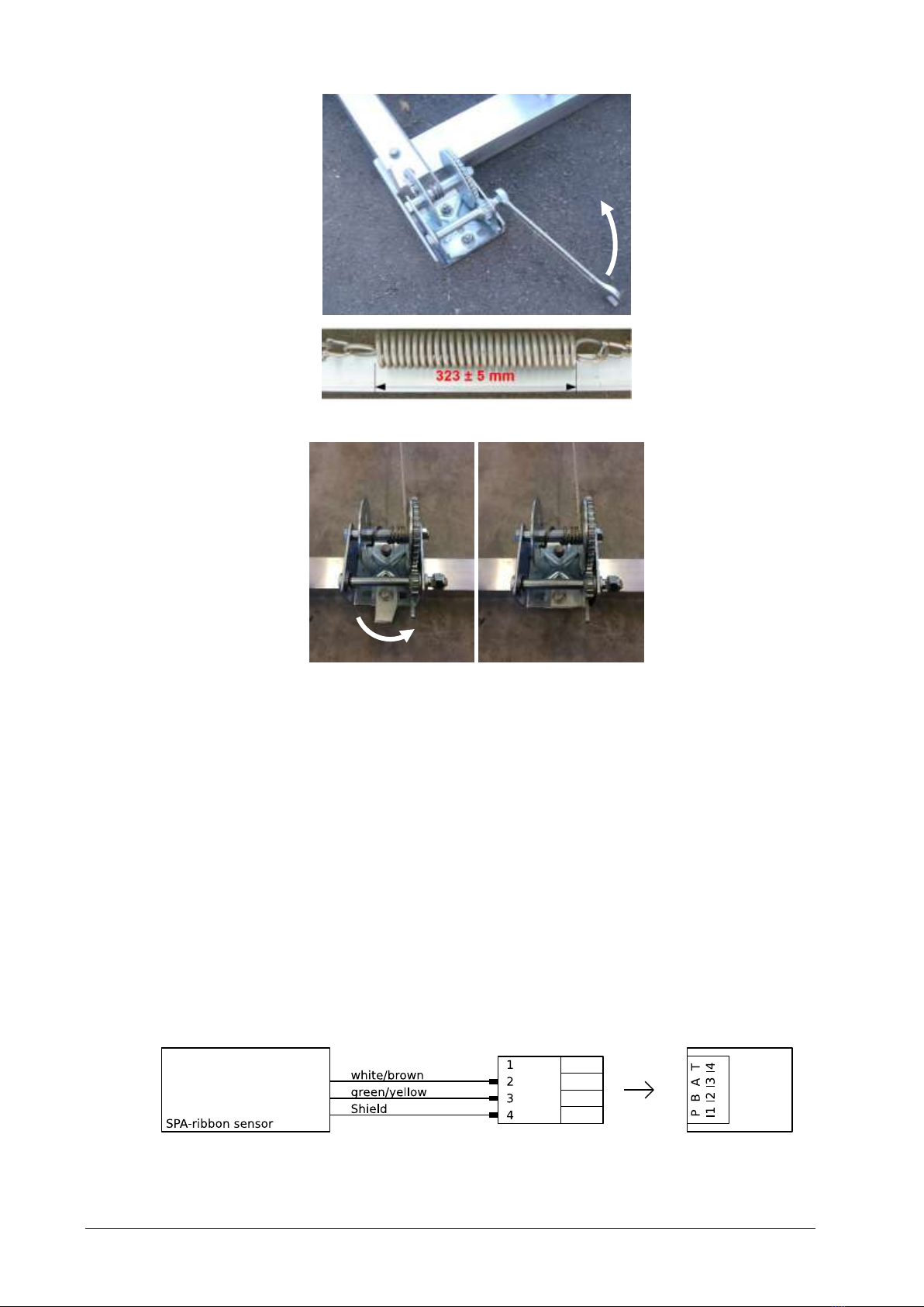
12
6. Secure the winch by turning the lug into its right position.
7. Secure the sensor cable with the provided clamp.
8. Attach the 4 plastic clips onto the ribbon-sensor with the supplied bolts. The spaces between the
clips should be equal along the ribbon (65 cm). Make sure the thickened edges of the ribbon are
placed in the notches of the clips.
9. Attach the positioning supports to the clips.
6.2.3 Control cabinet
1. Mount the control cabinet to its dedicated place (frame of SMA-frame or mast in the vicinity).
2. Feed the sensor cable of the SMA ribbon-sensor and the cable of the power supply through the
cable glands into the cabinet and secure them with the provided nuts.
6.2.4 Wiring
1. Connect the SMA-sensor cable to the I1 terminal of the controller. The sensor wires are connected
to the SMA-2 controller as illustrated below.
Figure 2: Wiring of SMA ribbon-sensor

13
Wire color
Pin
Function
Description
-
1
-
not connected
white/brown
2
Receive
Received signal
green/yellow
3
Transmit
Transmitted signal
shield
4
-
cable shield
Table 3: Connection wires of SMA ribbon-sensor
6.2.5 Power supply
The SMA-2 is designed for extreme environmental conditions at remote sites with no grid connection.
The sensor switches automatically into standby-mode between measurements and thus consumes
only approx. 0.1 Ah per day at a typical measurement interval between 5 to 10 minutes. Thus, the
device can be powered by a 12V-solar-generator mounted in the vicinity.
The installation of the SMA-2 is now complete. Please follow the instructions in Configuration to com-
plete the setup.
6.3 Lightning protection
If the underground at the measurement site permits sufficient current dissipation it is strongly recom-
mended to equip the device with properly dimensioned lightning protection. Consult an expert for
advice.
6.4 Maintenance
The SMA-2 generally does not require any special maintenance. However, we recommend to check
the following regularly:
-Sits the installation firmly on the ground?
-Is the SMA ribbon-sensor damaged and tightly stretched? Are the clips in the upright position?
-Is the sensor cable and its protection tubing intact or broken, e.g. damage by rodents?

14
7Communication
7.1 SMA-2 controller
The controller of the SMA-2 triggers the measurements of the connected sensor, acquires data and
calculates the snow parameters. It returns the data via RS-485 or SDI-12.
7.1.1 Connection terminals
All available connection terminals are listed in Table 4.
Figure 3: Connection terminals of SP-2 controller
Terminal
PIN
Description
TRIG
2
Trigger input 2 (not available)
G
Ground
1
Trigger input 1
G
Ground
BUS 1
B
RS-485 B (to data acquisition device)
A
RS-485 A (to data acquisition device)
S
SDI-12 (to data acquisition device)
G
Ground
BAT
-
Supply voltage (-)
-
Supply voltage (-)
+
Supply Voltage (+), 9.0 to 24.0 VDC
+
Supply Voltage (+), 9.0 to 24.0 VDC

15
I1
T
Optional temperature input
A
SMA ribbon-sensor
B
SMA ribbon-sensor
P
Shield of SMA ribbon-sensor
I2
T
Optional temperature input
A
Used with SMA-2 (ribbon sensor)
B
Used with SMA-2 (ribbon sensor)
P
Used with SMA-2 (ribbon sensor)
I3
T
Optional temperature input
A
Used with SMA-2 (ribbon sensor)
B
Used with SMA-2 (ribbon sensor)
P
Used with SMA-2 (ribbon sensor)
I4
T
Optional temperature input
A
Used with SMA-2 (ribbon sensor)
B
Used with SMA-2 (ribbon sensor)
P
Used with SMA-2 (ribbon sensor)
AIN 1,2
G
Ground
1
Analog input 1
2
Analog input 2
AIN 3,4
G
Ground
3
Analog input 3
4
Analog input 4
BUS 2
G
Ground
S
SDI-12 (from sensor)
A
RS-485 A (from sensor)
B
RS-485 B (from sensor)
OUT 1,2
G
Ground
1
Switched supply voltage 1
2
Switched supply voltage 2
OUT 3,4
G
Ground
3
Switched supply voltage 3
4
Switched supply voltage 4
Table 4: Connection terminals of SMA-2 controller

16
7.2 Communication with a PC
Communication between the SMA-2 and a PC can be established with a USB to RS-485 converter. Per-
form the following steps to set up the communication between the SMA-2 and your PC:
1. Install the Commander software on your PC.
2. If not already done, install the driver of the USB to RS-485 converter.
3. Connect the USB to RS-485 converter to a USB-port on your PC and the BUS 1 terminal of the SMA-
2 as illustrated in Figure 4.
Figure 4: Connection of USB to RS-485 converter
4. Start the Commander Software.
5. Click on Communication assistant on the right-hand side of the Commander window.
6. Select Serial Connection and press Next.

17
7. Make sure the SMA-2 is powered and press Next.
8. Select Sensor (9600 Bd) and press Next.
9. Tick Select port and select the COM port that was assigned to the USB/RS-232 converter; then click
Next.

18
If more than one COM ports are listed and you are not sure which one to select, open the Windows
Device Manager (press and type device manager) and expand the menu Ports (COM & LPT). By
unplugging and re-plugging your USB/RS-232 converter you can identify the number of the desired
port.
10. The Commander now searches for connected devices. This may take a few minutes. Upon comple-
tion, press No to the question “Do you want to save the station?”.
11. Click Finish. Upon completion, the newly created connection is displayed in the Communication
section of the Commander.
12. Open the Parameters (F2) tab and click Download parameters from device.

Table of contents
Other SOMMER Measuring Instrument manuals


