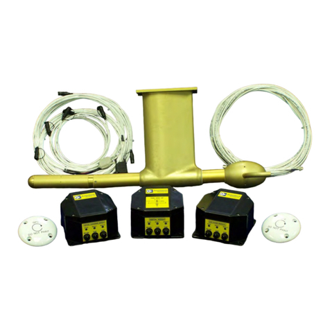
Aventech AIMMS-20 User manual

Rev: 1.00
Date: 11.22.2013
Page: 1 of 40
AIMMS-20
OPERATING MANUAL
Document-P/N: AIMMS20-OM
© Aventech Research Inc. 2013. All Rights Reserved.
AIMMS-20
Aircraft Integrated Meteorological
Measurement System
OPERATING MANUAL
Document-P/N: AIMMS20-OM
Aventech Research Inc.
110 Anne Street South, Unit 23
Barrie, Ontario, Canada L4N 2E3
Tel: (705) 722-4288
Fax: (705) 722-9077
Web: www.aventech.com

Rev: 1.00
Date: 11.22.2013
Page: 2 of 40
AIMMS-20
OPERATING MANUAL
Document-P/N: AIMMS20-OM
© Aventech Research Inc. 2013. All Rights Reserved.
Issued
Date Name Signature Function
21.11.2013 Bruce H. Woodcock DE
Checked
Date Name Signature Function
22.11.2013 Bruce H. Woodcock DE
Approved
Date Name Signature Function
22.11.2013 Bruce H. Woodcock HD
Customer Approval (as required)
Date Name Signature Function
Table of Functions
CUST Customer
DE Design Engineer
HD Head of Design Engineering
PM Production Manager
QM Quality Manager

Rev: 1.00
Date: 11.22.2013
Page: 3 of 40
AIMMS-20
OPERATING MANUAL
Document-P/N: AIMMS20-OM
© Aventech Research Inc. 2013. All Rights Reserved.
NOTICES
WARRANTY
Aventech Research Inc. products are warranted to be free from defects in material and
workmanship under normal use and service for a period of one year beginning on the
date of shipment. This warranty extends only to the original buyer or end-user customer
of an Aventech Research Inc. authorized reseller. This warranty does not apply to any
product which, in Aventech Research Inc’s opinion, has been misused, altered,
neglected, contaminated, or damaged by accident or abnormal conditions of operation
or handling.
Aventech Research Inc’s warranty obligation is limited, at Aventech Research Inc’s
option, to refund of the purchase price, free of charge repair, or replacement of a
defective product which is returned within the warranty period.
To obtain warranty service, return the product to the nearest Aventech Research Inc.
authorized reseller, or direct to the address provided below:
Aventech Research Inc.
110 Anne Street South, Unit 23
Barrie, Ontario, Canada L4N 2E3
Tel: (705) 722-4288
Fax: (705) 722-9077
Shipping costs to Aventech Research Inc. are the responsibility of the end customer
(FOB Destination). Aventech Research Inc. assumes no risk for damage in transit.
Following warranty repair, the product will be returned to Buyer, transportation prepaid
(FOB Destination). If Aventech Research Inc. determines that failure was caused by
neglect, misuse, contamination, alteration, accident, or abnormal condition of operation
or handling, including overvoltage failures caused by use outside the product’s specified
rating, or normal wear and tear of mechanical components, Aventech Research Inc. will
provide an estimate of repair costs and obtain authorization before commencing the
work. Following repair, the product will be returned to the Buyer transportation prepaid
and the Buyer will be billed for the repair and return transportation charges (FOB
Shipping Point).
Aventech Research Inc. warrants that product firmware will operate substantially in
accordance with its functional specifications. Aventech Research Inc. does not warrant
that firmware will be error free or operate without interruption.

Rev: 1.00
Date: 11.22.2013
Page: 4 of 40
AIMMS-20
OPERATING MANUAL
Document-P/N: AIMMS20-OM
© Aventech Research Inc. 2013. All Rights Reserved.
The material contained in this document is provided “as is,” and is subject to being
changed, without notice, in future editions. Further, to the maximum extent permitted by
applicable law, Aventech Research Inc. disclaims all warranties, either express or
implied, with regard to this manual and any information contained herein, including but
not limited to the implied warranties of merchantability and fitness for a particular
purpose. Aventech Research Inc. shall not be liable for errors or for incidental or
consequential damages in connection with the furnishing, use, or performance of this
document or of any information contained herein. Should Aventech Research Inc. and
the user have a separate written agreement with warranty terms covering the material in
this document that conflict with these terms, the warranty terms in the separate
agreement shall control.
THIS WARRANTY IS BUYER'S SOLE AND EXCLUSIVE REMEDY AND IS IN LIEU OF
ALL OTHER WARRANTIES, EXPRESS OR IMPLIED, INCLUDING BUT NOT LIMITED
TO ANY IMPLIED WARRANTY OF MERCHANTABILITY OR FITNESS FOR A
PARTICULAR PURPOSE. AVENTECH RESEARCH INC. SHALL NOT BE LIABLE
FOR ANY SPECIAL, INDIRECT, INCIDENTAL, OR CONSEQUENTIAL DAMAGES OR
LOSSES, INCLUDING LOSS OF DATA, ARISING FROM ANY CAUSE OR THEORY.
COPYRIGHT
© Aventech Research Inc. 2013. No part of this manual may be reproduced in any form
or by any means (including electronic storage and retrieval or translation into a foreign
language) without prior agreement and written consent from Aventech Research Inc. as
governed by Canadian and international copyright laws.

Rev: 1.00
Date: 11.22.2013
Page: 5 of 40
AIMMS-20
OPERATING MANUAL
Document-P/N: AIMMS20-OM
© Aventech Research Inc. 2013. All Rights Reserved.
RECORD OF REVISIONS
Date Issue Page Paragraph Firmware
Revision Comments
21.11.2013 1.00 All All Preliminary Draft
22.11.2013 1.00 All All Release

Rev: 1.00
Date: 11.22.2013
Page: 6 of 40
AIMMS-20
OPERATING MANUAL
Document-P/N: AIMMS20-OM
© Aventech Research Inc. 2013. All Rights Reserved.
TABLE OF CONTENTS
1 INTRODUCTION .....................................................................................................................8
2 SYSTEM OVERVIEW..............................................................................................................9
2.1AirDataProbe(ADP)...........................................................................................................................9
2.2InertialMeasurementUnit(IMU).....................................................................................................10
2.3GPSPhaseModule(GPS)..................................................................................................................11
2.4CentralProcessingModule(CPM)....................................................................................................12
2.5Communications...............................................................................................................................13
3 AIMMS-20 SETUP AND CALIBRATION ...............................................................................14
3.1PreparationofLaptop/Computer...................................................................................................14
3.2Measurements..................................................................................................................................14
3.3CalibrationFlightProcedure.............................................................................................................15
3.3.1Pre‐FlightProcedure..................................................................................................................15
3.3.2AerodynamicCalibrationManoeuvres......................................................................................15
3.3.3InertialSystemCalibrationManoeuvres....................................................................................17
3.3.4PostFlightProcedure.................................................................................................................18
4 AIMMS CONFIGURATION UTILITY SOFTWARE USER’S MANUAL (aimcfg.exe) .............19
4.1Installingaimcfg................................................................................................................................19
4.2Startingaimcfg..................................................................................................................................19
4.3MainProgramWindow.....................................................................................................................21
4.4FileMenu..........................................................................................................................................21
4.4.1LogDownload............................................................................................................................21
4.4.2ErrorLogDownload...................................................................................................................23
4.4.3ViewBroadcastData..................................................................................................................23
4.4.4RawDataCapture......................................................................................................................24
4.4.5COMPort....................................................................................................................................24
4.4.6UpdateFirmware.......................................................................................................................25
4.5Setup.................................................................................................................................................27
4.6AirDataCalibrationParameters.......................................................................................................28

Rev: 1.00
Date: 11.22.2013
Page: 7 of 40
AIMMS-20
OPERATING MANUAL
Document-P/N: AIMMS20-OM
© Aventech Research Inc. 2013. All Rights Reserved.
4.7Cross‐AxisAlignmentErrors..............................................................................................................29
4.8Version..............................................................................................................................................30
5 TECHNICAL SPECIFICATIONS............................................................................................31
5.1AIRDATAPROBE(ADP).....................................................................................................................31
5.2INERTIALMEASUREMENTUNIT(IMU)..............................................................................................31
5.3CENTRALPROCESSINGMODULE(CPM)............................................................................................31
5.4METEOROLOGICAL............................................................................................................................32
5.4.1Temperature..............................................................................................................................32
5.4.2RelativeHumidity.......................................................................................................................32
5.4.3Three‐DimensionalWind...........................................................................................................32
5.5ELECTRICAL........................................................................................................................................32
5.6ENVIRONMENTAL.............................................................................................................................33
5.7WEIGHT.............................................................................................................................................33
APPENDIX A: AIMMS-20 SERIAL COMMUNICATION FORMAT .............................................34
A.1Introduction......................................................................................................................................34
A.2HardwareConfiguration...................................................................................................................34
A.3PacketFormat...................................................................................................................................34
A.3.1DataBlock,StandardMeteorologyPacket(ID=0)...................................................................35
A.3.2DataBlock,Aircraft‐StateDataPacket(ID=1)..........................................................................36
A.3.3DataBlock,PurgeFlowPacket(ID=4)......................................................................................37
A.3.4DataBlock,InternalProbeTemperaturePacket(ID=5)..........................................................37
A.3.5DataBlock,CANMessageForwarding(RawData)Packet(ID=22)..........................................38
A.4Packet‐BasedCommandInputtoAIMMS‐20CPM..........................................................................39
A.4.15‐HoleProbePurgeInitiation....................................................................................................39
A.4.2ChangeProbeInternalBlock‐HeaterSet‐Point.........................................................................40

Rev: 1.00
Date: 11.22.2013
Page: 8 of 40
AIMMS-20
OPERATING MANUAL
Document-P/N: AIMMS20-OM
© Aventech Research Inc. 2013. All Rights Reserved.
1 INTRODUCTION
The Aventech Research Inc. AIMMS-20 (Aircraft Integrated Meteorological
Measurement System) is an integrated, turn-key system for measuring accurate,
real-time meteorological data on airborne platforms. The meteorological data set
includes temperature, humidity, three-dimensional winds (speed, direction and
vertical) and turbulence. The data generated by the system is broadcast in real-time
via an RS-232 serial communications link to either a GPS navigation system or data
acquisition system.
This document provides a step by step description on how to setup and calibrate
the AIMMS-20 instrumentation for your aircraft or helicopter airframe. Section 2
provides an overall description of the components of the AIMMS-20 system. Section
3 provides detail on how to perform the initial setup of the system followed by a
description of the flight manoeuvres that must be performed in order to calibrate the
system. In order to set up and calibrate the system, the user will utilize Aventech’s
aimcfg PC-based software utility. A user’s guide for the aimcfg software utility is
provided in Section 4. Technical specifications for the system are provided in
Section 5. If the end user wishes to integrate the AIMMS-20 serial broadcast data
stream into their dedicated data acquisition system, details of the broadcast format
can be found in Appendix A.

Rev: 1.00
Date: 11.22.2013
Page: 9 of 40
AIMMS-20
OPERATING MANUAL
Document-P/N: AIMMS20-OM
© Aventech Research Inc. 2013. All Rights Reserved.
2 SYSTEM OVERVIEW
The AIMMS-20 system consists of four modules: an Air Data Probe (ADP) which is
mounted external to the aircraft, an Inertial Measurement Unit (IMU), a GPS Phase
Module (GPS) and a Central Processing Module (CPM). The following section of
this manual describes each of the system components in order to familiarize you
with the system.
2.1 Air Data Probe (ADP)
The Air Data Probe is mounted external to the aircraft and is the component of the
AIMMS-20 which measures static pressure, the three-dimensional flow vector
relative to the aircraft frame of reference, Outside Air Temperature (OAT), Relative
Humidity (RH) and turbulence.
The three-dimensional flow vector is measured using a series of five pressure ports
located on the hemispherical nose of the ADP’s measurement boom and a ring of
static pressure ports slightly aft of the measurement boom nose. Using this set of
pressure ports measurement of the barometric, pitot-static, differential angle-of-
attack and differential side-slip pressure measurements can be obtained which
define the three-dimensional flow vector.
OAT and RH measurements are made using a small 0.038” diameter bead
thermistor and thermoset polymer RH sensor respectively. Both sensors are located
in a reverse-flow chamber at the aft end of the probe to protect them from direct
impact with particulates and larger objects in the free stream flow.
With your AIMMS-20 system you will have received one of two Air Data Probe types
depending on the airframe for the planned installation, an under-wing version as
shown in Figure 1 or a sting-mount version as shown in Figure 2.
The under-wing ADP is typically utilized for fixed-wing installations while the sting-
mount ADP is typically utilized in rotary-wing installations. In some cases end users
have also used the sting-mount probe for fixed-wing installations with their own
mounting bracket design.

Rev: 1.00
Date: 11.22.2013
Page: 10 of 40
AIMMS-20
OPERATING MANUAL
Document-P/N: AIMMS20-OM
© Aventech Research Inc. 2013. All Rights Reserved.
Figure 1: AIMMS-20 Under-Wing Air Data Probe Installation
Figure 2: AIMMS-20 Sting-Mount Air Data Probe Installation
2.2 Inertial Measurement Unit (IMU)
The IMU is a six-degree of freedom inertial measurement unit consisting of three
MEMS accelerometers and three MEMS rate gyros. Utilizing inexpensive MEMS-
based measurement devices provides a high-accuracy, low cost method of
measuring the dynamic, high-frequency motion of an airborne platform. However,
the compromise is that MEMS-based measurement devices have poorer long term
DC stability. The AIMMS-20 system compensates for this DC instability using a
single-axis GPS carrier-phase system which is described in Section 2.3.

Rev: 1.00
Date: 11.22.2013
Page: 11 of 40
AIMMS-20
OPERATING MANUAL
Document-P/N: AIMMS20-OM
© Aventech Research Inc. 2013. All Rights Reserved.
Figure 3: AIMMS-20 Inertial Measurement Unit
2.3 GPS Phase Module (GPS)
The GPS Phase module is a two antenna, single baseline GPS carrier-phase
subsystem. Accurate, DC-stable attitude of the baseline between two GPS
antennae either mounted laterally (wingtip to wingtip) or longitudinally (wingtip to
wingtip or fore / aft) on the airborne platform can be determined using the GPS
carrier-phase measurements from the two GPS receivers located in the module.
Lateral antennae configurations are typically used on fixed-wing aircraft while
longitudinal antennae configurations can be utilized on fixed or rotary wing aircraft.
Although the attitude measurement performed using this technique is stable it
possesses a fairly low frequency response (2.5 Hz). Higher frequency dynamic
information is provided by the IMU described in Section 2.2. The mathematical
algorithm used to optimally combine the two sets of data is called an Extended
Kalman Filter (EKF) and runs in the firmware loaded in the CPM described in
Section 2.4.

Rev: 1.00
Date: 11.22.2013
Page: 12 of 40
AIMMS-20
OPERATING MANUAL
Document-P/N: AIMMS20-OM
© Aventech Research Inc. 2013. All Rights Reserved.
Figure 4: AIMMS-20 GPS Phase Module
2.4 Central Processing Module (CPM)
The CPM is essentially the main computational center for the AIMMS-20 system.
CPM firmware utilizes acceleration and angular-rate information from the IMU and
carrier-phase information from the GPS to compute the precise three-dimensional
orientation of the aircraft using an Extended Kalman Filter (EKF) algorithm. In
parallel, the three-dimensional winds relative to the aircraft are evaluated from air
data provided by the ADP. These data, when combined with aircraft attitude and
velocity, are transformed into the earth reference frame to provide the final three-
dimensional wind output.
The CPM also acts as the main interface between the aircraft spray navigation
system and the rest of the AIMMS-20.
Aircraft power is provided to the AIMMS-20 through the CPM module which steps
the input voltage down +12 VDC and distributes it to power the balance of the
modules through the Controller Area Network (CAN) cables.
The real-time aircraft state (attitude) and meteorological (temperature, humidity,
wind speed, wind direction and turbulence) data provided by the AIMMS-20 is
broadcast on the second serial port of the CPM as two unique aircraft state and
meteorological packets which can be read by a host computing device such as a
GPS navigation system or data acquisition system. Details of the format of these
packets can be found in Appendix A.

Rev: 1.00
Date: 11.22.2013
Page: 13 of 40
AIMMS-20
OPERATING MANUAL
Document-P/N: AIMMS20-OM
© Aventech Research Inc. 2013. All Rights Reserved.
Figure 5: AIMMS-20 Central Processing Module
2.5 Communications
The four AIMMS-20 modules communicate with each other via a high-speed, digital
serial Controller Area Network (CAN) bus. The four conductor cable connected
between the modules provides power to each of the modules and communication
between them.
Communication between the AIMMS-20 and a host computing device (GPS
navigation or data acquisition system) is via a standard RS-232 serial port.

Rev: 1.00
Date: 11.22.2013
Page: 14 of 40
AIMMS-20
OPERATING MANUAL
Document-P/N: AIMMS20-OM
© Aventech Research Inc. 2013. All Rights Reserved.
3 AIMMS-20 SETUP AND CALIBRATION
3.1 Preparation of Laptop / Computer
The first step in setting up your AIMMS-20 system is to install the aimcfg software
utility provided with the system onto a laptop computer which will be used to interact
with the system. The laptop will require an RS232 serial communications port, either
built into the computer or as a PCMCIA or USB peripheral adapter. Instructions on
installing the software are provided in Section 4.1.
Before proceeding further, you should first familiarize yourself with the aimcfg PC-
based software utility. The aimcfg User’s Manual is provided as Section 4 of this
document.
3.2 Measurements
Two pieces of information will be required concerning the physical installation on
your aircraft. First, the straight-line distance between the two GPS antennas,
referred to as the antenna baseline, must be measured (see Fig. 6). This can be
determined from known station information utilized for the unstallation, or measured
directly using a plumb-bob first to mark the position on the ground directly below the
each antenna, then measuring the distance between these two marks on the
ground using a long tape measure. Similarly, the location of the ADP relative to the
aircraft centreline needs to be determined, referred to as the ADP Offset. This is the
straight-line distance from the centre of the probe to the centreline of the aircraft.
The ADP Offset is positive if the ADP is located on the starboard wing and negative
if located on the port wing. Retain these measurements for later input as part of
AIMMS-20 configuration setup using the aimcfg software utility.
Figure 6: Definition of Antenna Baseline Length and ADP Offset

Rev: 1.00
Date: 11.22.2013
Page: 15 of 40
AIMMS-20
OPERATING MANUAL
Document-P/N: AIMMS20-OM
© Aventech Research Inc. 2013. All Rights Reserved.
3.3 Calibration Flight Procedure
The following section describes the manoeuvres that are to be flown, while
recording data, during the calibration flight. The resulting data file provides the
required information so that the calibration coefficients that have to be programmed
into the AIMMS-20 can be determined in order to provide a real-time wind solution.
Two different procedures exist for flight calibration. The first procedure is required to
determine aerodynamic errors induced by the aircraft itself (see Section 3.3.2). The
second procedure is required to capture small alignment errors (i.e. cross-axis
error) between the gyros, accelerometers, GPS antenna baseline and the primary
reference frame of the IMU (see Section 3.3.3). Data required for analysis of the
aerodynamic calibration flight is automatically recorded in the FLASH memory on-
board the CPM, which can be downloaded after landing using the aimcfg software
utility (Section 4.4.1). However, data requirements for the GPS-IMU cross-axis
calibration are such that all raw system data must be recorded. Raw data can be
captured using the aimcfg utility (see Section 4.4.4).
Step by step instructions are provided followed by a graphical depiction of the flight
segment.
3.3.1 Pre-Flight Procedure
i) Power up the AIMMS-20 system.
ii) Start aircraft, taxi and ascend to an altitude at which you will be insured smooth
air with a constant wind field. Depending on the prevailing meteorological
conditions this may be well above the temperature inversion and/or cloud top.
3.3.2 Aerodynamic Calibration Manoeuvres
i) Select three true air speeds (TAS) within a range from a comfortable margin
above aircraft stall to a comfortable margin below maximum cruise. The mid-
range TAS is typically selected at your spray release airspeed. Select the
minimum and maximum calibration speeds in consultation with the operations
manager and pilot flying the calibration flight.
ii) Start the calibration procedure by setting up on a true north heading at the lowest
airspeed selected in step 3 above.

Rev: 1.00
Date: 11.22.2013
Page: 16 of 40
AIMMS-20
OPERATING MANUAL
Document-P/N: AIMMS20-OM
© Aventech Research Inc. 2013. All Rights Reserved.
iii) At this lowest airspeed perform a yaw manoeuvre yawing the aircraft
approximately 5 degrees to port followed by 5 degrees to starboard, or vice-
versa, at a rate of approximately 5 to 10 seconds into the yaw and 5 to 10
seconds back out for a total of 20 to 40 seconds for the complete manoeuvre.
iv) Once the yaw manoeuvre is complete, hold the lowest airspeed on a constant
true north heading for approximately 10 seconds and then increase the airspeed
slowly to your mid-range or spray release airspeed. Once stabilized repeat the
yaw manoeuvre at this airspeed.
v) Once again, when the yaw manoeuvre is complete, hold the operational airspeed
on a constant true north heading for approximately 10 seconds and then increase
the airspeed slowly to your maximum selected airspeed, determined in step 3.
vi) At the highest TAS repeat the yaw manoeuvre.
vii) Turn the aircraft around 180 degrees at a moderate bank angle (approx. 30
degrees) and set up on a true south heading at the highest airspeed.
viii) Repeat the yaw manoeuvre.
ix) Decrease the airspeed continuously to the mid-range airspeed.
x) Perform the yaw manoeuvre at the operational TAS setting.
xi) Decrease the airspeed once again continuously to the lowest airspeed.
xii) Perform one last set of yaw manoeuvres at the lowest airspeed.

Rev: 1.00
Date: 11.22.2013
Page: 17 of 40
AIMMS-20
OPERATING MANUAL
Document-P/N: AIMMS20-OM
© Aventech Research Inc. 2013. All Rights Reserved.
TRUE NORTH
Maximum TAS Maximum TAS
Mid-Range TAS Mid-Range TAS
Minimum TAS Minimum TAS
TRUE SOUTH
Figure 7: Aerodynamic Calibration Manoeuvres
3.3.3 Inertial System Calibration Manoeuvres
i) Select any heading which will locate the aircraft in low or no traffic airspace to
perform the following manoeuvre.
ii) After stabilizing perform a 360 degree orbit to starboard at a bank angle of 15
degrees. When complete stabilize on the original heading for approximately 5
seconds.
iii) Repeat step ii) using an approximate bank angle of 30 degrees.
iv) Repeat step ii) again using an approximate bank angle of 45 degrees.

Rev: 1.00
Date: 11.22.2013
Page: 18 of 40
AIMMS-20
OPERATING MANUAL
Document-P/N: AIMMS20-OM
© Aventech Research Inc. 2013. All Rights Reserved.
v) Repeat steps ii) to iv) to port which will be six orbits in total.
Figure 8: Inertial System Calibration Manoeuvres
3.3.4 Post Flight Procedure
i) Return to base and land.
or the e-mail address of your dedicated Aventech support engineer for post-
processing. The new calibration parameters will be e-mailed to you for
programming into the AIMMS-20 system.

Rev: 1.00
Date: 11.22.2013
Page: 19 of 40
AIMMS-20
OPERATING MANUAL
Document-P/N: AIMMS20-OM
© Aventech Research Inc. 2013. All Rights Reserved.
4 AIMMS CONFIGURATION UTILITY SOFTWARE USER’S
MANUAL (aimcfg.exe)
4.1 Installing aimcfg
The installation software package is provided as a compressed file archive
aimcfgXXX.zip where XXX is the version number. Unzip the file archive using
standard Windows tools and place the files in a temporary destination folder. From
the list of files within this folder you should see the program file setup.exe. Double
click on this file to launch the installer and follow the subsequently provided
instructions. Please make note of the directory to which the aimcfg files are
installed.
4.2 Starting aimcfg
Before starting the aimcfg utility program, make sure the serial cable provided with
the system is connected between your PC and the RS-232 port of the CPM module.
The serial cable has a 6-pin female circular connector on one end and two DSub-9
serial connectors on the other. Connect the DSub-9 connector labelled COM1 with
a black hood to your computer at this point in order to communicate with, and setup,
the AIMMS-20. Once the communications cable is connected, and the AIMMS
system connected to power, turn on the AIMMS.
Navigate to the installation folder and you should see the executable file named
aimcfgXXX.exe where XXX is the version number. You can create a shortcut to the
desktop for the aimcfgXXX.exe file for ease of access in the future. Double-click on
this file to launch the AIMMS setup utility (Note: make sure the AIMMS has been
powered up for at least 5 s before launching the program. This is the amount of time
it takes for the AIMMS system software residing within the CPM to start).
Immediately after the program launches, you will be presented with the small dialog
box shown below confirming the baud rate at which the program will attempt to
make a serial connection with the AIMMS-20.

Rev: 1.00
Date: 11.22.2013
Page: 20 of 40
AIMMS-20
OPERATING MANUAL
Document-P/N: AIMMS20-OM
© Aventech Research Inc. 2013. All Rights Reserved.
After clicking OK, the AIMMS configuration utility will check for any system errors
that might have been logged. The first dialog box shown below will then pop-up
indicating that aimcfg is checking the Error Log. After a brief period of time (less
than a few seconds), the second dialog box shown below will appear indicating the
status of the log. If log events are noted, they will be downloaded to a file in the
aimcfg installation directory.
If a communications failure occurs, a dialog box will appear indicating a “timeout”
condition. This error condition indicates that communications have not been
established with the system. Additional action should be taken at this point to
determine the cause of the communication failure:
1) Check all connections, including that you are connected to COM1 (black
hood) on the serial cable.
2) Make sure the unit has power applied.
3) Check that the correct baud rate is set.
Click “OK” to continue.
Other manuals for AIMMS-20
1
Table of contents
Other Aventech Measuring Instrument manuals
Popular Measuring Instrument manuals by other brands
Toshiba
Toshiba Density (Consistency) Meter LQ500 user guide
Elcomponent
Elcomponent SPCPro2 user manual

Ampetronic
Ampetronic FSM User handbook
Extech Instruments
Extech Instruments 407750 user guide
BIO RAD
BIO RAD CFX96 Touch Installation quick guide
ITT Controls
ITT Controls Barton Nuclear 227A user manual
Magnescale
Magnescale DK812S Series instruction manual
Agilent Technologies
Agilent Technologies 81950A user guide
ALTONOVUS
ALTONOVUS OR-01 instruction manual
TDE Instruments
TDE Instruments Digalox DPM72-MP instruction manual
DynaQuip
DynaQuip WaterCop Classic Owner's manual & installation guide
Ziton
Ziton ZR4-RL installation guide
