2DE4050
2
22
2. SPECIFICATIONS
. SPECIFICATIONS. SPECIFICATIONS
. SPECIFICATIONS
Number of Outputs: 8, open collector type, 100 mA max. each
Unit ID: 8-bit code
Expansion Bus: 4 wires (+12V, 0V, DATA and COMMON)
Bus Length: Up to 1 km (0.62 miles) with single expander and
100 Ω resistance per wire.
Output Polarities: N.O. or N.C., as set by switch on MCR-308
Tamper Switch Ratings: 0.1 A, 30 VDC
Input Voltage: 10 -16 VDC (supplied via the expansion bus).
Current Drain: Approximately 7 mA standby, 13 mA maximum.
Operating Temperature Range: -10°C to 49°C (14°F to 120°F).
Size (H x W x D): 108 x 165 x 38 mm (4-1/4 x 6-1/2 x 1-1/2 in.)
Weight (cabinet with single MCX-8): 191 g (6.75 oz).
3
33
3. INSTALLATION
. INSTALLATION. INSTALLATION
. INSTALLATION
3.1 Mounting
The MCX-8 is supplied in a plastic cabinet, as described in Para.
1.2. Install the plastic cabinet as follows:
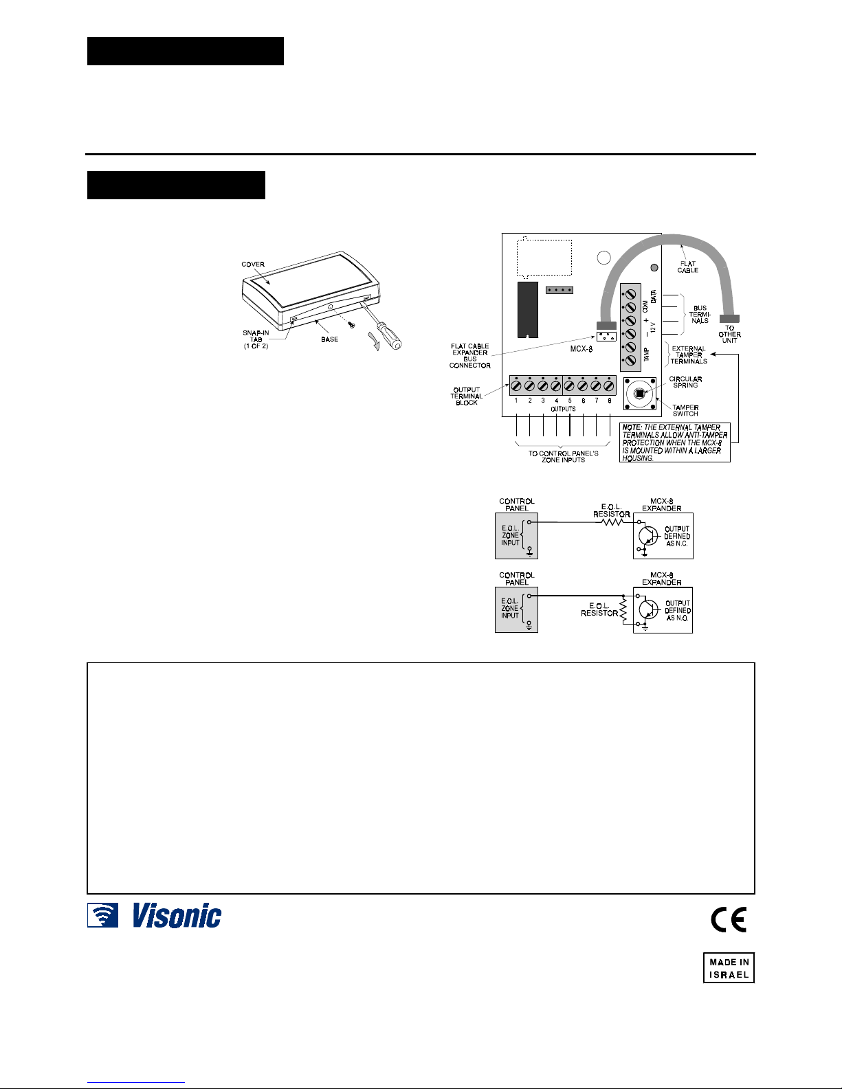
A. Remove the screw that
secures the cover to the
base (Fig. 6).
B. Insert a small screw-
driver blade into the slot
near one of the snap-in
tabs, as shown. Carefully
flex the cover edge out,
until the tab disengages
the dent. Repeat this
with the other tab.
Figure 6. Separating the Cover
from the Base
C. Remove the cover and use the mounting and wiring holes as
required for the particular installation.
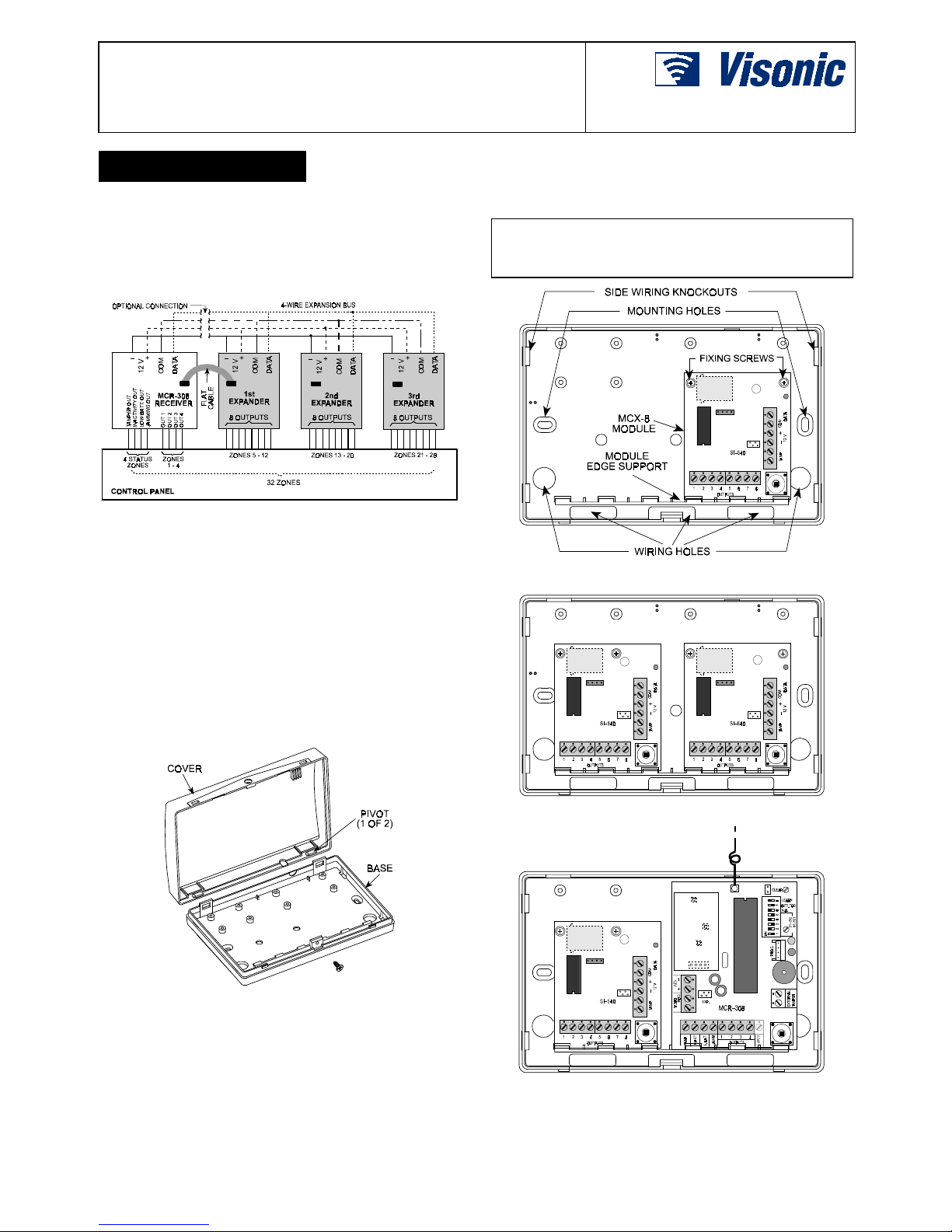
3.2 Expansion Bus Hookup
Since the MCR-308 receiver and the MCX-8 expander usually
share the same cabinet, the easiest way to link them is to use the
short flat cable assembly supplied with each MCX-8 (Figure 7).
To continue the bus to additional expanders, use the 4 bus
terminals on each unit (refer to Figure 1). Connect each terminal
on the bus terminal block to its counterpart on the other unit.
3.3 Output Circuit Wiring
After connection via the expansion bus to the MCR-308, the MCX-8
will have a common ground with the control panel via the MCR-308.
You only have to connect each output terminal of the MCX-8 to one
of the control panel’s zone inputs.
If the control panel zone inputs are defined as E.O.L., you must
use appropriate E.O.L. resistors (see Figure 8).
3.4 Using an External Tamper Switch
The built-in tamper switch and the TAMP terminals are connected
in parallel. If the external TAMP terminals are used, make sure that
no pressure is applied on the actuating lever of the built-in tamper
switch - remove the circular spring if necessary.
Figure 7. Printed Circuit Board Layout
Figure 8. WIRING E.O.L. Zones
WARRANTY
WARRANTYWARRANTY
WARRANTY
Visonic Ltd. and/or its subsidiaries and its affiliates ("the Manufacturer") warrants its
products hereinafter referred to as "the Product" or "Products" to be in conformance with
its own plans and specifications and to be free of defects in materials and workmanship
under normal use and service for a period of twelve months from the date of shipment by
the Manufacturer. The Manufacturer's obligations shall be limited within the warranty
period, at its option, to repair or replace the product or any part thereof. The Manufacturer
shall not be responsible for dismantling and/or reinstallation charges. To exercise the
warranty the product must be returned to the Manufacturer freight prepaid and insured.
This warranty does not apply in the following cases: improper installation, misuse,
failure to follow installation and operating instructions, alteration, abuse, accident or
tampering, and repair by anyone other than the Manufacturer.
This warranty is exclusive and expressly in lieu of all other warranties, obligations or
liabilities, whether written, oral, express or implied, including any warranty of
merchantability or fitness for a particular purpose, or otherwise. In no case shall the
Manufacturer be liable to anyone for any consequential or incidental damages for breach
of this warranty or any other warranties whatsoever, as aforesaid.
This warranty shall not be modified, varied or extended, and the Manufacturer does not
authorize any person to act on its behalf in the modification, variation or extension of this
warranty. This warranty shall apply to the Product only. All products, accessories or
attachments of others used in conjunction with the Product, including batteries, shall be
covered solely by their own warranty, if any. The Manufacturer shall not be liable for any
damage or loss whatsoever, whether directly, indirectly, incidentally, consequentially or
otherwise, caused by the malfunction of the Product due to products, accessories, or
attachments of others, including batteries, used in conjunction with the Products.
The Manufacturer does not represent that its Product may not be compromised and/or
circumvented, or that the Product will prevent any death, personal and/or bodily injury
and/or damage to property resulting from burglary, robbery, fire or otherwise, or that the
Product will in all cases provide adequate warning or protection. User understands that a
properly installed and maintained alarm may only reduce the risk of events such as
burglary, robbery, and fire without warning, but it is not insurance or a guarantee that such
will not occur or that there will be no death, personal damage and/or damage to property
as a result.
The Manufacturer shall have no liability for any death, personal and/or bodily injury
and/or damage to property or other loss whether direct, indirect, incidental,
consequential or otherwise, based on a claim that the Product failed to function.
However, if the Manufacturer is held liable, whether directly or indirectly, for any loss or
damage arising under this limited warranty or otherwise, regardless of cause or origin, the
Manufacturer's maximum liability shall not in any case exceed the purchase price of the
Product, which shall be fixed as liquidated damages and not as a penalty, and shall be the
complete and exclusive remedy against the Manufacturer.
Warning: The user should follow the installation and operation instructions and among
other things test the Product and the whole system at least once a week. For various
reasons, including, but not limited to, changes in environmental conditions, electric or
electronic disruptions and tampering, the Product may not perform as expected. The user
is advised to take all necessary precautions for his /her safety and the protection of
his/her property.
6/91
VISONIC LTD. (ISRAEL): P.O.B 22020 TEL-AVIV 61220 ISRAEL. PHONE: (972-3) 645-6789, FAX: (972-3) 645-6788
VISONIC INC. (U.S.A.): 10 NORTHWOOD DRIVE, BLOOMFIELD CT. 06002-1911. PHONE: (860) 243-0833, (800) 223-0020 FAX: (860) 242-8094
VISONIC LTD. (UK): FRASER ROAD, PRIORY BUSINESS PARK, BEDFORD MK44 3WH. PHONE: (0870) 730-0800 FAX: (0870) 730-0801
INTERNET: www.visonic.com
VISONIC LTD. 1999 MCX-8 DE4050- (REV. 1, 12/99)