Vissani QR255 Series User manual

Under Cabinet Range Hood
Campana extractora para in-
stalación bajo gabinete
# QR255 (SERIES)
Owner’s Manual
Manual del usario Rev. 20221101
Additional parts located inside range hood.
Piezas adicionales ubicadas dentro de la campana extractora.
IMPORTANT / IMPORTANTE
QR255 (SERIES) 2
ENGLISH
Table of Contents
Safety Information ..................................2
Warranty
One Year Limited Warranty...........................4
Warranty Claim Procedure...........................4
Pre-Installation
Tools/Materials Required ............................5
Package Contents .................................6
Hardware Included.................................6
Planning Installation ...............................7
Installation .......................................10
Operation. . . . . . . . . . . . . . . . . . . . . . . . . . . . . . . . . . . . . . . . . 17
Maintenance
Replacing Filters .................................18
Replacing Lights .................................18
Care and Cleaning
Range Hood .....................................19
Filters..........................................19
Troubleshooting ...................................20
6SHFLğFDWLRQV
Wiring Diagram ..................................21
External Range Hood Diagram.......................22
Service Parts......................................23
MANUAL DEL USARIO ...............................24
Safety Information
READ AND SAVE THESE INSTRUCTIONS
:DUQLQJ7RUHGXFHWKHULVNRIğUHHOHFWULFVKRFNRULQMXU\WR
SHUVRQVREVHUYHWKHIROORZLQJ
1. Use this unit only in the manner intended by the manufacturer. If
you have any questions, contact the manufacturer.
2. Before servicing or cleaning unit, switch power off at service
panel and lock service disconnecting means to prevent
power from being switched on accidentally. When the service
disconnecting means cannot be locked, securely fasten a
prominent warning device, such as a tag, to the service panel.
3. ,QVWDOODWLRQZRUNDQGHOHFWULFDOZLULQJPXVWEHGRQHE\TXDOLŵHG
person(s) in accordance with all applicable codes and standards,
LQFOXGLQJŵUHUDWHGFRQVWUXFWLRQ
4. 6XIŵFLHQWDLULVQHHGHGIRUSURSHUFRPEXVWLRQDQGH[KDXVWLQJ
RIJDVHVWKURXJKWKHŶXHFKLPQH\RIIXHOEXUQLQJHTXLSPHQW
to prevent back drafting. Follow the heating equipment
manufacturer’s guideline and safety standards such as those
published by the National Fire Protection Association (NFPA),
and the American Society for Heating, Refrigeration and Air
Conditioning Engineers (ASHRAE), and the local code authorities.
5. When cutting or drilling into a wall or ceiling, do not damage
electrical wiring and other hidden utilities.
6. Ducted fans must always be vented to the outdoors.
WARNING: FUEL (GAS) BURNING RANGES MUST BE VENTED
OUTDOORS USING, AT MINIMUM, METAL DUCTWORK AND RANGE
HOODS OF SUFFICIENT CAPACITY. Follow your fuel burning
equipment manufacturer’s guidelines, as well as, all applicable
safety standards published by the National Fire Protection
Association (NFPA), and the American Society for Heating,
Refrigeration and Air Conditioning Engineers (ASHRAE), and your
local code authorities.
'$1*(5 Turn off the power circuit breaker or the power
switch on the junction box before installing or servicing
this unit. Touching circuitry inside the range hood while it is
energized will result in death or serious injury.
'$1*(5 All electrical wiring must be properly installed,
insulated, and grounded. Improper insulation and grounding
will result in deadly electrical shock.
'$1*(5 If installing this unit over a gas range, turn off the
gas at the source before installing or servicing this unit.
:$51,1* Attempting to install or service this unit when
you do not have the necessary technical or electrical
background could result in personal injury.
:$51,1* The unit has sharp edges. Always wear safety
gloves during installation, cleaning, or servicing.
:$51,1* $OZD\VOHDYHVDIHW\JULOOVDQGŵOWHUVLQSODFH
Without these components, operating fans could catch on to
KDLUŵQJHUVRUORRVHFORWKLQJ
:$51,1* Stay clear of the rotating fan when the motor
is running.
:$51,1* Keep this appliance clean and free of grease
DQGUHVLGXHEXLOGXSDWDOOWLPHVWRSUHYHQWŵUHV
&$87,21 This device is for general ventilating use only.
Do not use to exhaust hazardous or explosive materials and
vapors.

3
Please contact [email protected] or 1-888-449-9197EHWZHHQDPSP(670RQGD\)ULGD\IRUIXUWKHUDVVLVWDQFH
ENGLISH
Safety Information (continued)
COOKING SAFETY INFORMATION
1. Never leave the range hood unattended when in use.
2. 1HYHUFRRNRYHURSHQŶDPHVXQGHUWKHUDQJHKRRG
3. Always turn the range hood on when cooking at high heat
RUZKHQFRRNLQJŶDPLQJIRRGV
4. The minimum installation distance above the range (D) is 18 in.
(458 mm). Use extra caution as the surface of the range hood
may become extremely hot to the touch if the range is operated
on high power for an extended amount of time.
5. 8VHFDXWLRQZKHQFRRNLQJZLWKRLORUZLWKGHHSIU\HUV
2YHUKHDWLQJPD\FDXVHRLOWRUHDFKLWVŶDVKSRLQWDQGLJQLWH
Used oil will ignite at lower temperatures than fresh oil. Heat
oils slowly on low to medium setting.
6. Avoid boil overs, as they may cause smoking and greasy
spillovers that could ignite.
7. 7RSUHYHQWEXUQVRUŵUHVDOZD\VXVHFRRNZDUHDSSURSULDWHWR
the size of the heating element that you are using.
8. ,QHYHQWRIDFRRNLQJŵUHREVHUYHWKHIROORZLQJ
Be careful to avoid burns.
6PRWKHUŶDPHVZLWKDFORVHŵWWLQJOLGFRRNLHVKHHWRU
PHWDOWUD\WKHQWXUQRIIWKHEXUQHU,IWKHŶDPHVGRQRWJR
RXWLPPHGLDWHO\HYDFXDWHDQGFDOOWKHŵUHGHSDUWPHQW
1HYHUSLFNXSDŶDPLQJSDQ
Do not use water, including wet dishcloths or towels, as you
could cause a steam explosion.
Use an extinguisher only if: (a) you have a class ABC
H[WLQJXLVKHUDQG\RXNQRZKRZWRRSHUDWHLWEWKHŵUHLV
VPDOODQGFRQWDLQHGLQWKHDUHDZKHUHLWVWDUWHGFWKHŵUH
GHSDUWPHQWLVEHLQJFDOOHGDQGG\RXFDQŵJKWWKHŵUHZLWK
your back to the exit.
CLEANING SAFETY INFORMATION
1. 7KHIDQDQGFDVVHWWHŵOWHUVPXVWEHFOHDQHGSHULRGLFDOO\DQG
kept free from accumulation of cooking residue. Old and worn
ŵOWHUVPXVWEHUHSODFHGLPPHGLDWHO\
2. Never disassemble parts to clean. Parts should be disassembled
E\TXDOLŵHGSHUVRQVRQO\
:$51,1* 7RUHGXFHWKHULVNRIŵUHXVHRQO\PHWDOGXFW
work. Never use plastic duct work.
:$51,1* 7RUHGXFHWKHULVNRIŵUHRUHOHFWULFVKRFNGR
not use this range hood with with any external solid state
speed control device.
&$87,21For general ventilation use only. Do not use the
range hood fans to exhaust hazardous or explosive vapours.
&$87,21 Never dispose of cigarette ashes, ignitable
substances, or any foreign objects in fans.
&$87,21 7RUHGXFHULVNRIŵUHDQGWRSURSHUO\H[KDXVW
DLUEHVXUHWRGXFWDLURXWVLGHGRQRWYHQWH[KDXVWDLULQWR
spaces within walls or ceilings or into attics, crawl spaces,
or garage.

QR255 (SERIES) 4
ENGLISH
Warranty
ONE YEAR LIMITED WARRANTY
A thorough inspection must be made before installation and any damage must be promptly reported. We will not be liable for failures or
damage that could have been discovered or avoided by proper inspection and testing prior to installation.
Vissani warrants this product to be free from defects in materials or workmanship for one (1) year from the date of purchase. Proof of
purchase (original sales receipt) from the original consumer purchaser must be made available to Vissani for all warranty claims.
7KLVZDUUDQW\LVQRQWUDQVIHUDEOHDQGVKDOOEHYRLGHGLIWKHXQLWLVUHPRYHGIURPLWVLQLWLDOLQVWDOODWLRQRULILWLVQRWLQVWDOOHGIROORZLQJWKH
manufacturer’s instructions. It does not apply in the event of product damage due to the use of other than genuine replacement parts,
5HSODFHPHQWSDUWVPD\EHREWDLQHGE\HPDLODW[email protected] or by calling 1-888-449-9197 EHWZHHQDPSP(670RQGD\
)ULGD\LQVWDOODWLRQHUURUDEXVHPLVXVHRULPSURSHUFDUHDQGPDLQWHQDQFHZKHWKHUSHUIRUPHGE\DSOXPEHUFRQWUDFWRUVHUYLFHSURYLGHURU
member of the purchaser’s household). The warranty excludes damage due to aggressive air or water conditions, harsh or abrasive cleaners
and/or materials.
Under no circumstance shall we be held liable for personal injury or property damage resulting from improper installation or use of this
product. We will not be held liable for inconvenience caused by loss of use of this product, costs incurred for materials,removal and installation
of replacement units, or any other incidental or consequential damages. Costs relating to obtaining access for repair or replacement are the
responsibility of the user.
Our obligation shall be limited to the repair or replacement of a unit (at our discretion) that may prove, by our sole examination, to be defective
under normal use and service during the warranty period.
$Q\IDLOXUHRIWKLVSURGXFWWKDWLVQRWWUDFHDEOHWRDGHIHFWLQPDWHULDORUZRUNPDQVKLSLVQRWFRYHUHGE\WKLVZDUUDQW\7KHVHQRQZDUUDQWDEOH
items include, but are not limited to:
Improper installation not in accordance with manufacturer’s instructions.
Dents and/or scratches incurred during shipping, handling, or installation.
&KDQJHLQFRORURUŵQLVKGXHWRFKHPLFDOXVDJH
Damage caused by failure to follow care and cleaning guidelines, including damage caused by the use of abrasive cleaners.
Alterations made to the unit by the purchaser or installer.
'DPDJHFDXVHGE\DFFLGHQWDOLPSDFWŵUHŶRRGIUHH]LQJDQGQRUPDOZHDU
%HQGVDQGZDUSLQJFDXVHGE\IRUFHGFRQQHFWLRQVRYHUWLJKWHQHGŵWWLQJVDQGLQDGHTXDWHVXSSRUWGXULQJLQVWDOODWLRQ
Any damage to light bulbs.
WARRANTY CLAIM PROCEDURE
If a claimable defect occurs or replacement parts are needed, please contact our customer service team at [email protected] or
1-888-449-9197 EHWZHHQDPSP(670RQGD\)ULGD\
Before you make your call, please ensure that you have:
Model number or description.
Proof of sale.
Details regarding the defect and/or part number.
Name(s) and address(es) of the owner and/or installer.

5
Please contact [email protected] or 1-888-449-9197EHWZHHQDPSP(670RQGD\)ULGD\IRUIXUWKHUDVVLVWDQFH
ENGLISH
Pre-Installation
TOOLS/MATERIALS REQUIRED (NOT SUPPLIED)
Measuring tape Level Utility knife
Pencil &HUWLŵHG
Duct Tape
Adjustable
wrench
Phillips screwdriver Flathead
screwdriver
Needle nose
pliers
Hammer Electric drill Safety goggles
Safety gloves

QR255 (SERIES) 6
ENGLISH
Pre-Installation (continued)
PACKAGE CONTENTS
Carefully check the range hood for damage and for missing parts prior to installation. If there is any damage or if you are missing parts,
GRQRWSURFHHGZLWKWKHLQVWDOODWLRQ5HSRUWGDPDJHDQGPLVVLQJSDUWVLPPHGLDWHO\'RQRWGLVSRVHRISDFNDJLQJEHIRUH\RXDUHVDWLVŵHG
with your new range hood.
BGHFD
A
E
C
Components
D - H Inside
Range Hood
Part Description Quantity
A Range hood 1
B Charcoal Filter 1
C+\EULG%DIŶH)LOWHUV 2
D Rectangular damper (located inside the hood) 1
E Round adapter (located inside the hood) 1
F Brackets for frameless cabinet (located inside the hood) 2
G%UDFNHWIRUIUDPHGFDELQHWOHIWORFDWHGLQVLGHWKHKRRG 1
H%UDFNHWIRUIUDPHGFDELQHWULJKWORFDWHGLQVLGHWKHKRRG 1
HARDWARE INCLUDED
NOTE:
Parts not shown in actual size.
AA BB CC
DD EE
AA Long tapping screws (ST4x18mm) 6
BB 6KRUWWDSSLQJVFUHZV67[)+PP 10
CC Wire Connectors 2
DD Washer 4
EE Countersunk wood screw (4x10mm) 6

7
Please contact [email protected] or 1-888-449-9197EHWZHHQDPSP(670RQGD\)ULGD\IRUIXUWKHUDVVLVWDQFH
ENGLISH
Pre-Installation (continued)
PLANNING INSTALLATION
1XPEHURISHRSOHUHTXLUHG 1
1. Before installation, measure all distances to ensure the proper
position of the range hood (A).
The minimum distance (1) from the cooking surface to the
UDQJHKRRGLVLQPP,I\RXUUDQJHVSHFLŵHVD
different distance, use the greater distance of the two. For
best performance, this distance (1) should not exceed 25 in.
(635 mm).
Dimension (2) should be at least 30 in (762 mm). The range
hood should be approximately the same size as the cook top.
2. If the bottom of the cabinet (3) above the location where the range
hood is to be installed is recessed, attach appropriately sized wood
ŵOOHUVWULSVRQHDFKVLGHXVLQJZRRGVFUHZVRUXVHWKHVXSSOLHG
installation brackets for framed cabinets.
3. Screws are provided to secure the range hood to most types of
FDELQHWVEXWFRQVXOWDTXDOLŵHGLQVWDOOHUWRYHULI\WKDWWKHVXSSOLHG
screws are suitable for your cabinets.
4. Put a thick, protective covering over your counter, cooktop, or
range to protect it from damage and dirt during installation.
Remove any hazardous objects around the area.
:$51,1* Always wear safety goggles and gloves during
installation.
9(17,1*237,216
a. Determine if your existing venting system is top venting or back venting, and ensure that the openings in the cabinet or wall for the
damper and for power access are in appropriate locations and are of appropriate sizes, as per Fig. 3 if it is top venting or Fig. 4 if it is
back venting. For top venting option (Fig. 3), if you are using the round adapter, the opening should be A and B only. If you are using
the rectangular damper, opening should be B and C only.
b. If this is a new installation, choose the venting method that suits your needs. Cut out openings for the damper and for power access
in the cabinet bottom or back wall, depending on the direction of venting chosen.
DIA.1.26"
(32mm)
DIA.7.4"
(188mm)
0.94" (24mm)
11.2” (285mm)
2.12” (54mm)
4.5”
(115mm)
3.58”
(91mm)
DIA.1.26"
(32mm)
10.25" (260mm)
10.25"
(260mm)
11.2” (285mm)
3.58”
(91mm)
0.25” (6.4mm) 0.8” (20mm)
Fig. 3: Top Venting Option Fig. 4: Back Venting Option
1.4" (36mm)
QR255 (SERIES) 8
ENGLISH
Pre-Installation (continued)
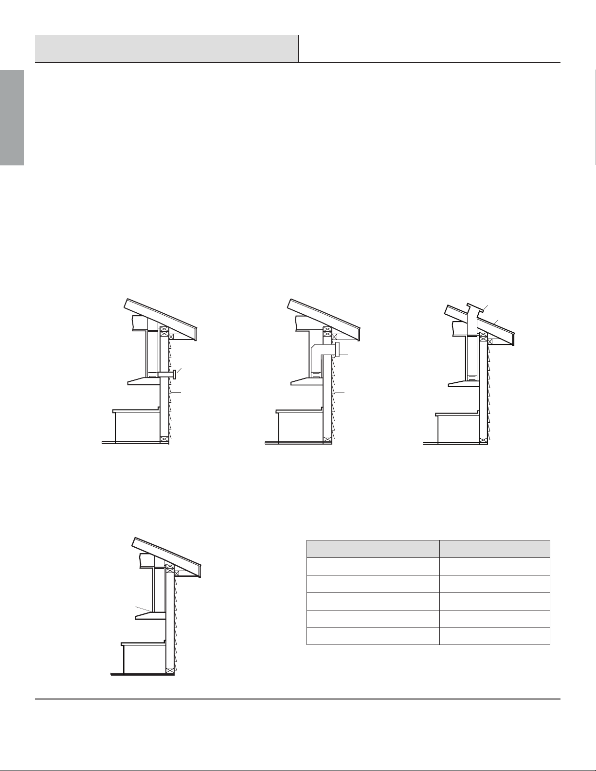
)2//2:7+(6(*8,'(/,1(6:+(1,167$//,1*'8&7:25.
Your venting system must vent to the outdoors either horizontally through the back wall (13) or vertically through the roof (14)
(refer to Fig. 5/Fig. 6/Fig. 7).
Use round metal duct work with a uniform diameter of 7 in (177 mm). The total duct run in the venting system should not be more
than 35 ft (10.7 m).
&DOFXODWHWKHWRWDOHIIHFWLYHOHQJWKRIWKHGXFWZRUNE\DGGLQJWKHHTXLYDOHQWOHQJWKVLQWKHWDEOHVKRZQ)LJ)RUHDFKŵWWLQJ
used add the length of the equivalent straight duct used in the system.
)DVWHQDOOFRQQHFWLRQVEHWZHHQSLHFHVRIGXFWZLWKVKHHWPHWDOVFUHZVDQGWDSHDOOMRLQWVZLWKFHUWLŵHGGXFWWDSH
If you must turn the path of the duct work using elbows, keep the number of elbows to a minimum for effective performance and
use no more than three 90° elbows. Ensure that there is a minimum of 18 in (458 mm) of straight vent between each elbow. Elbow
as far away from the range hood’s exhaust opening as possible.
&DSWKHH[WHULRURIWKHGXFWZLWKDZDOOFDSRUURRIFDS1HYHUXVHLQPPODXQGU\W\SHZDOOFDSV8VHFDXONLQJWR
seal exterior wall or roof opening around the cap.
The venting system must have a damper. If the roof or wall cap has a damper, do not use the damper supplied with the range hood.
13
15
Horizontal Wall Venting
Fig.5
Vertical Roof Venting
14
16
Fig.7
13
Horizontal Wall Venting
Fig.6
15
For interior venting system (air does not exhaust to outdoors) (Fig. 8):
,QLQWHULRUYHQWHGLQVWDOODWLRQVDLULVUHFLUFXODWHGWKURXJKDFKDUFRDOŵOWHUDQGH[KDXVWHGWKURXJKWKHWRSRIWKHUDQJHKRRG6HH
installation section for more details.
17
Fig. 8
Equivalent Length Chart
Type of duct Length added
45° Elbow 3 ft (0.91 m)
90° Elbow 5 ft (1.52 m)
90° Flat elbow 12 ft (3.66 m)
9 ft (2.74 m) Straight duct 9 ft (2.74 m)
Wall cap 0 ft (0 m)
Fig. 9

9
Please contact [email protected] or 1-888-449-9197EHWZHHQDPSP(670RQGD\)ULGD\IRUIXUWKHUDVVLVWDQFH
ENGLISH
Pre-Installation (continued)
WIRING CONNECTION REQUIREMENTS
,QVWDOODWLRQZRUNDQGHOHFWULFDOZLULQJPXVWEHGRQHE\DTXDOLŵHG
person(s) in accordance with all applicable codes and standards,
LQFOXGLQJŵUHUDWHGFRQVWUXFWLRQ
OBSERVE ALL GOVERNING CODES AND ORDINANCES WARNINGS
Electrical grounding is required for this range hood. Check with
DTXDOLŵHGHOHFWULFLDQLI\RXDUHQRWVXUHZKHWKHUWKHUDQJH
hood is properly grounded.
)DLOXUHWRIROORZHOHFWULFDOUHTXLUHPHQWVPD\UHVXOWLQDŵUH
A fuse in the neutral or grounding circuit could result in
electrical shock.
If the hot/cold water pipe is interrupted by plastic nonmetallic
gaskets or other materials, DO NOT use for grounding.
DO NOT GROUND TO A GAS PIPE.
,03257$17,WLVWKHFXVWRPHUőVUHVSRQVLELOLW\WRFRQWDFWDTXDOLŵHG
electrical installer and assure that the electrical installation is adequate
and complies with the National Electrical Code, or CSA standards, as
well as all local codes and ordinances.
1. Save installation instructions for electrical inspector’s use.
2. If codes permit and a separate ground wire is used, it is
UHFRPPHQGHGWKDWDTXDOLŵHGHOHFWULFLDQGHWHUPLQHLIWKH
ground path is adequate.
3. DO NOT use an extension cord or adapter plug with this
appliance.
4. The range hood must be connected with copper wire only.
5. The range hood should be connected directly to the junction (or
FLUFXLWEUHDNHUER[WKURXJKŶH[LEOHDUPRXUHGRUQRQPHWDOOLF
sheathed copper cable. Allow some slack in the cable so the
appliance can be moved if servicing is ever necessary.
6. A UL listed or CSA approved conduit connector must be provided
at each end of the power supply cable (at the range hood and at
the junction box).
7. :KHQPDNLQJWKHHOHFWULFDOFRQQHFWLRQFXWDLQFP
hole in the wall. A hole cut through wood must be sanded until
smooth. A hole through metal must have a grommet.
8. When cutting or drilling into the wall or ceilling, do not damage
electrical wiring and other hidden utilities.
9. Wire size must conform to all local codes and ordinances. The
latest edition requirements of the National Electrical Code ANSI/
1)3$RUWKHODWHVWHGLWLRQ&6$6WDQGDUGV&&DQDGLDQ
(OHFWULFDO&RGH3DUWDQG&1R0
'$1*(5 Risk of electrical shock. This range hood must be
properly grounded.
'$1*(5 Turn off the power circuit breaker or the
power switch on the junction box before installing this
unit. Touching circuitry inside the range hood while it is
energized will result in death or serious injury.
'$1*(5 All electrical wiring must be properly installed,
insulated, and grounded. Improper insulation and grounding
will result in deadly electrical shock.
NOTE:
Temporarily wire the range hood to test it for proper operation. If
the range hood does not operate correctly, do not proceed with the
installation.
Remove the grease shield panel of the range hood (see
Fig. 13) to access the electrical wire leads.
Use the power supply cable to connect the range hood
(A) directly to the junction box or circuit breaker box.
8VHDŶH[LEOHDUPRXUHGRUQRQPHWDOOLFVKHDWKHG
copper cable only. Never use an extension cord or
adapter plug.
&RQQHFWD8/OLVWHGRU&6$DSSURYHGFRQGXLWFRQQHFWRU
to each end of the power supply cable (at the range
hood and at the junction box). Connect the 2 colored
wires from the range hood (A) to the corresponding
wires from the electrical source: black to black (live),
white to white (neutral), and the house grounding wire
to the green ground screw. Use either the top hole (1) or
the back hole (2) of the range hood depending on your
installation type as shown in Fig. 10.
Turn the power on, and ensure that the lights and the
fan are operating correctly.
Once you have tested the electrical connection,
disconnect the power supply cable and wires from the
electrical source before proceeding with the rest of the
installation.
CC
CC
BLACK
WIRES
WHITE
WIRES GREEN
GROUND SCREW
QR255 (SERIES) 10
ENGLISH
Installation
WARNING: FUEL (GAS) BURNING RANGES MUST BE VENTED OUTDOORS USING, AT MINIMUM, METAL DUCTWORK AND RANGE HOODS OF SUFFICIENT CAPACITY.
Follow your fuel burning equipment manufacturer’s guidelines, as well as, all applicable safety standards published by the National Fire Protection Association
(NFPA), and the American Society for Heating, Refrigeration and Air Conditioning Engineers (ASHRAE), and your local code authorities.
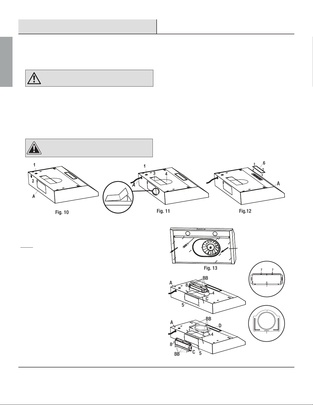
REMOVING THE ELECTRICAL KNOCK-OUT HOLE
:$51,1* Always wear safety goggles and gloves during
installation.
&KRRVHWKHDSSURSULDWHHOHFWULFDONQRFNRXWKROHWRUHPRYHIRU\RXU
installation type. Use the top hole (1) if your electrical supply is in
the cabinet and the back hole (2) if your electrical supply is on the
wall below the cabinet (refer to Fig. 10).
8VHDŶDWKHDGVFUHZGULYHUDQGSOLHUVWRJHQWO\UHPRYHWKHHOHFWULFDO
NQRFNRXWKROH
Use an approved strain relief to ensure the knock out hole does not
damage the insulation of the the electrical supply cable
&$87,21 Please use caution when removing the knock
outs and vent covers to ensure none of the internal
components are accidentally damaged.
REMOVING THE VENTING HOLE
(FOR EXTERIOR VENTING)
Choose the venting hole to remove for your installation type. Use
the top holes (3 & 4) for a top venting installation and the back
hole (5) for a back venting installation. See Installing the damper
section for more details.
Carefully remove the cover (3, 4 or 5) of the appropriate venting
KROHXVLQJDŶDWKHDGVFUHZGULYHURUQHHGOHQRVHSOLHUVUHIHU
Fig. 11). Be careful not to damage any internal components when
removing the knockouts and not to leave any debris inside the
range hood (A).
(FOR INTERIOR VENTING)
If you are venting indoors, unscrew the 2 screws holding cover
(6) in place and remove the cover as per Fig. 12. DO NOT REMOVE
ANY OTHER VENTING HOLE COVER.
5
INSTALLING THE DAMPER
(SKIP THIS STEP IF YOU ARE USING INTERIOR VENTING)
Grease Shield
Fig. 14
3B
3A
3A
3B
D
E
NOTE:
Only install the damper if you are using a venting system that does not already have
a damper. If this hood replaces an existing unit, the location of the air exhaust can
YDU\IURPRQHPDQXIDFWXUHUWRDQRWKHU(QVXUHWKDWWKHGDPSHUğWVLQWKHH[LVWLQJ
opening before installing.
The damper and the adapter are located inside the range hood.
To access these parts, remove the grease shield if you have not
previously done so (see Fig. 13).
Choose to install the damper (D) either in the top
position (3A & B) for top venting or in the back position (5)
for back venting. Adapter (E) is used for top venting only and
installs in position 3A and 4.
Attach damper (D) or adapter (E) over chosen knockout opening.
Make sure the damper pivot is oriented on top such that the
damper stays closed when not in use.
Secure the damper (D) or adapter (E) to the range hood (A) with the
short tapping screws (BB).
Seal the damper (D) or adapter (E) to the range hood (A) on all four
sides with duct tape.

11
Please contact [email protected] or 1-888-449-9197EHWZHHQDPSP(670RQGD\)ULGD\IRUIXUWKHUDVVLVWDQFH
ENGLISH
Installation (continued)
NOTE:
This range hood can be installed to the cabinet with or without the use of the
supplied installation brackets.
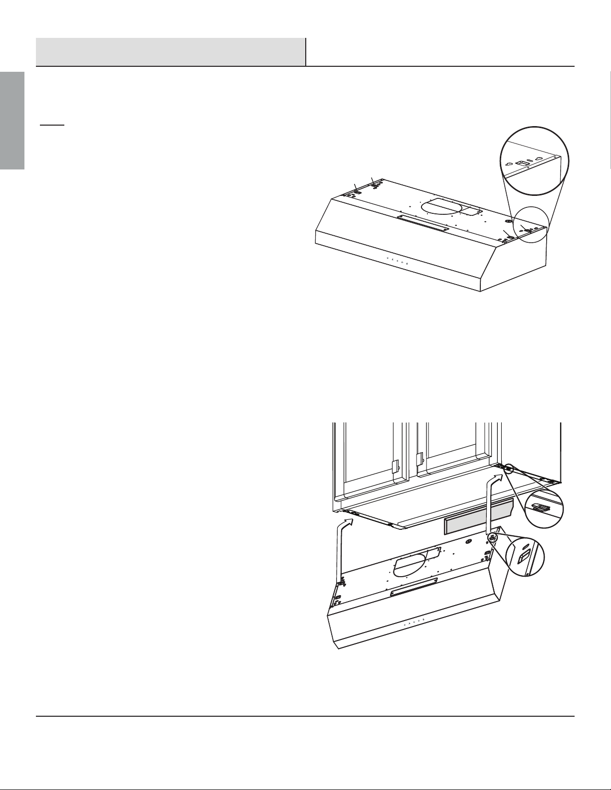
A. INSTALLATION WITHOUT MOUNTING BRACKETS
If you are installing this range hood to a framed cabinet install a 3
LQFKZLGHVSDFHURQHLWKHUVLGHRIWKHFDELQHWWRŵOOWKHYRLGVRWKDW
the range hood can be securely tightened to the cabinet.
/LIWWKHUDQJHKRRG$XSXQGHUWKHFDELQHWWRGHWHUPLQHLWVŵQDO
position. Mark the location of the four keyhole mounting slots (1) on
the underside of the cabinet.
Set the range hood (A) aside on a protective surface.
Drill four pilot holes in the locations that you marked.
Screw the four long tapping screws (AA) into the pilot holes.
Do not tighten the screws all the way – leave the screw
heads about 0.28 in (7 mm) from the cabinet surface.
Lift the range hood (A) into position, feeding the power
cable and the electrical wires through the power access
opening. Allow some slack in the cable and wires so that the
appliance can be moved if servicing is ever necessary.
Position the range hood (A) so the large end (2) of the
keyhole mounting slots (1) are over the screws (AA). Then
push the range hood (A) toward the wall so the screws (AA)
are in the neck (3) of the keyhole slots. Tighten the screws
(AA). Ensure that the range hood (A) is securely fastened to
the cabinet before releasing it.
If applicable, test the damper to ensure it rotates up and
down freely.
If applicable, connect the duct work to the range hood (A).
6HDOWKHMRLQWVZLWKGXFWWDSHWRHQVXUHDQDLUWLJKWŵW
B. INSTALLATION USING 1 PERSON INSTALL BRACKETS
B.1 FRAMELESS CABINET BRACKET INSTALLATION
Refer to the marking on brackets to determine the correct
installation side and orientation.
Flat end of the bracket with the arrow should face towards
you and the notched end should face the wall.
'$1*(5 Turn off the power circuit breaker or the
power switch on the junction box before installing this
unit. Touching circuitry inside the range hood while it is
energized will result in death or serious injury.
'$1*(5 If installing this unit over a gas range, turn off the
gas at the source before installing or servicing this unit.
Fig. 15
Fig. 16
QR255 (SERIES) 12
ENGLISH
Installation (continued)
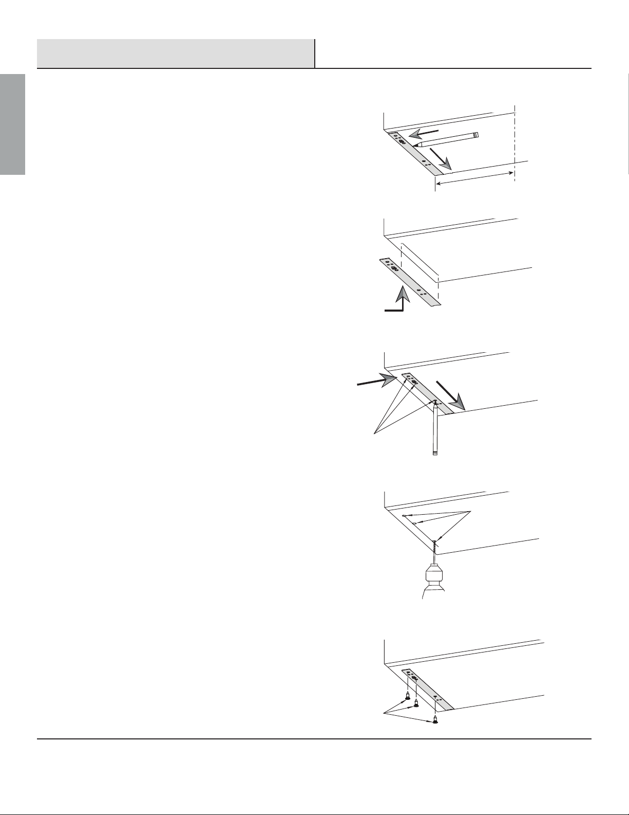
Align the bracket against the side edge of the 30 in
(762 mm) cabinet cabinet and the back wall. Draw a line
DORQJLQQHUHGJHRIWKHEUDFNHWDVVKRZQLQŵJ
Slide the bracket inwards and align it against the marked
line. Ensure the rear edge is tight against wall as shown
LQŵJ
Use a pencil to mark the location of the 3 center holes as
VKRZQLQŵJ
Set the bracket aside and drill three 7/64” holes in the
PDUNHGORFDWLRQVDVVKRZQLQŵJ
Secure the bracket to the cabinet using a Phillips
screwdriver and 3 supplied countersunk wood screws
((DVVKRZQLQŵJ
5HSHDWWKHDERYHSURFHGXUHWRLQVWDOOWKHUHPDLQLQJŶDW
bracket on the opposite side of the cabinet.
7/64”
Fig. 17-1
Fig. 17-2
Fig. 17-3
Fig. 17-4
EE
15 in
(381 mm)
Center Line

13
Please contact [email protected] or 1-888-449-9197EHWZHHQDPSP(670RQGD\)ULGD\IRUIXUWKHUDVVLVWDQFH
ENGLISH
Installation (continued)
B.2 FRAMED CABINET BRACKET INSTALLATION
Fig. 18
Refer to the marking on brackets to determine their
correct installation side and orientation.
Flat end of the bracket with the arrow should face
towards you and the notched end should face the wall.
Align the bracket against the inside edge of the 30 in
(762 mm) cabinet cabinet frame and the back wall. Mark
the location of 3 holes (out of the available 6 holes) as
VKRZQLQŵJ
Set the bracket aside and drill three 7/64” holes in the
PDUNHGORFDWLRQVDVVKRZQLQŵJXUH
Secure the bracket to the side frame using a screwdriver
and provided 18mm wood screws (AA). If a given
SUHGULOOHGSLORWKROHKDVVWULSSHGXVHWKHDGMDFHQW
mounting hole instead.
Repeat the above procedure to install the remaining framed
cabinet bracket on the opposite side of the cabinet.
Fig. 19-1
Fig. 19-2
7/64”
Fig. 19-3
AA
QR255 (SERIES) 14
ENGLISH
Installation (continued)
SECURING THE RANGE HOOD TO THE BRACKETS
Fig. 20
FR
R
F
NOTE:
The following procedure applies to both frame or frameless cabinet
bracket installations.
There are 2 pairs of recessed slots in the front and rear
of the range hood.
Rear (R) slots can be used to hold the range hood
WHPSRUDULO\LQSODFHZKLOHPDNLQJŵQDODGMXVWPHQWVWR
vent and electrical connections.
Front (F) slots are used to hold the range hood in place to
permanently secure it to the cabinet.
Temporarily hang the hood on the rear (R) brackets.
While holding the hood check the electrical and duct
connections.
2QFHWKHLQWHJULW\RIWKHFRQQHFWLRQVKDVEHHQFRQŵUPHG
UHPRYHDQGKDQJWKHUDQJHKRRGLQLWVŵQDOORFDWLRQ
using the front (F) slots.
Fig. 21
AB

15
Please contact [email protected] or 1-888-449-9197EHWZHHQDPSP(670RQGD\)ULGD\IRUIXUWKHUDVVLVWDQFH
ENGLISH
Installation (continued)
Secure the range hood in place using the supplied
fasteners.
Frameless cabinet installation requires four long tapping
screws (AA) with washers. Use the two slots on each
side to secure the range hood directly to the cabinet
VKRZQLQŵJXUH
Framed cabinet installation requires four short tapping
screws (BB) with washers. Use the two slots on each
side to secure the range hood directly to the metal
EUDFNHWVKRZQLQŵJXUH
FINAL INSPECTION
Inspect all of the electrical and duct connections. Make
sure the damper assembly (or round duct adapter)
enters the ductwork and that the damper opens and
closes freely.
:KHQVDWLVŵHGZLWKWKHLQVWDOODWLRQUHLQVWDOl the grease
shield DQGWKHŵOWHUV
Restore the power to the range hood and ensure that the
lights and fan are operating correctly.
BB
BB
FRAMELESS CABINET
AA
AA
FRAMED CABINET
Fig. 22-1
Fig. 22-2
Fig. 23
Grease Shield

QR255 (SERIES) 16
ENGLISH
Installation (continued)
INSTALLING THE CHARCOAL FILTER
(SKIP THIS STEP IF YOU ARE USING EXTERIOR VENTING)
NOTE:
7KHFKDUFRDOğOWHUVKRXOGRQO\EHLQVWDOOHGLI\RXDUHYHQWLQJWKHUDQJHKRRGLQVLGHUHFLUFXODWLQJWKHDLU
5HPRYHHDFKFDVVHWWHŵOWHUE\OLIWLQJXSWKHŵOWHUFOLSDQGURWDWLQJWKHŵOWHUGRZQZDUGV
3ODFHWKHFKDUFRDOŵOWHU%LQSODFHHQVXUHWKDWLWFRYHUVWKHDLURXWOHWHQWLUHO\
5HLQVWDOOHDFKFDVVHWWHŵOWHU
1 2
34

17
Please contact [email protected] or 1-888-449-9197EHWZHHQDPSP(670RQGD\)ULGD\IRUIXUWKHUDVVLVWDQFH
ENGLISH
Operation
NOTE:
$OZD\VWXUQ\RXUUDQJHKRRGRQEHIRUH\RXVWDUWFRRNLQJWRHVWDEOLVKJRRGDLUĠRZLQ\RXUNLWFKHQ,WLVDOVRUHFRPPHQGHGWRXVHWKHLQWHJUDWHGVKXWGRZQ
delay timer to allow the range hood to evacuate the remaining heat and cooking gases after cooking is completed.
(1) (2) (3) (4) (5)
TURN ON RANGE HOOD
Press the SRZHUWLPHUEXWWRQ to quickly activate both the fan and the lights at the same time.
OR
Alternatively you can turn on the fan or the lights independently by pressing the light button (5) or any of the desired fan speed
buttons (2 or 3 or 4).
TURN OFF RANGE HOOD / TIMER DELAYED SHUTDOWN
Press the SRZHUWLPHUEXWWRQ while the range hood is on to activate the 3 minute shutdown delay timer. Both the fan and the
lights will turn off automatically after 3 minutes.
OR
Press the SRZHUWLPHUEXWWRQ for 3 seconds to turn off both the fan and the lights immediately.
OR
Alternatively you can turn off the fan or the lights independently by pressing the light button (5) or the active fan speed button
(2 or 3 or 4).
THREE LEVEL LIGHTING
Press the light button (5) to activate the lights at high level. Pressing the light button (5) consequent times will reduce the
intensity of the light to medium, low, and off.
Press the light button (5) for 3 seconds to turn off the lights immediately.

QR255 (SERIES) 18
ENGLISH
Maintenance
REPLACING HYBRID BAFFLE FILTER
+\EULGEDIŶHŵOWHUVVKRXOGEHFOHDQHGUHJXODUO\HLWKHUE\KDQG
RULQWKHGLVKZDVKHUXVLQJDZDUPDQGPLOGGLVKZDVKLQJ
GHWHUJHQWVROXWLRQ5HSODFHŵOWHUVWKDWDUHGDPDJHGZLWK
SXQFWXUHVEHQGVRUEURNHQIUDPHV:KHQŵOWHUVUHTXLUH
UHSODFHPHQWXVHRQO\JHQXLQHUHSODFHPHQWŵOWHUV
&KDUFRDOŵOWHUVVKRXOGRQO\EHXVHGLQLQGRRUYHQWHG
installations and should be replaced periodically (approximately
every 3 to 6 months), depending on frequency of use. Do not
DWWHPSWWRFOHDQFKDUFRDOŵOWHUV
REPLACING LIGHT BULBS
When light bulbs burn out, replace them with a 5W GU10 base
light bulb.
Turn off the range hood, disconnect it from its power
source, and ensure that the lights are cool.
Turn the bulb (1) in the direction indicated and pull it out
to remove it.
Push in the new bulb (2) in the direction indicated until
it locks into the socket. Do not release the bulb until
you are sure the bulb has been securely installed. Then
reconnect the power.
If new bulbs do not operate, ensure that they are
inserted correctly.
'$1*(5Turn off the power circuit breaker or the power
switch on the junction box before performing maintenance.
Touching circuitry inside the range hood while it is energized
will result in death or serious injury.
:$51,1* )DLOXUHWRUHSODFHZRUQRXWRUGDPDJHGŵOWHUV
ZLOOLQFUHDVHWKHULVNRIŵUH
:$51,1* Light bulbs can become hot when turned on.
Do not touch bulbs until they are switched off and cooled.
Touching hot bulbs could cause serious burns.
1
2

19
Please contact [email protected] or 1-888-449-9197EHWZHHQDPSP(670RQGD\)ULGD\IRUIXUWKHUDVVLVWDQFH
ENGLISH
Care and Cleaning
RANGE HOOD
:$51,1* )DLOXUHWRPDLQWDLQEDVLFVWDQGDUGVRIFDUHDQGFOHDQLQJRIWKHUDQJHKRRGZLOOLQFUHDVHWKHULVNRIŵUH
The range hood should be cleaned regularly (internally and externally) to preserve its appearance and performance.
'R 'R1RW
Always clean in the direction of the grain (original
polish lines).
Clean the range hood periodically with hot, soapy
water and a clean cotton cloth.
Always rinse well with clean water two or three
times after cleaning. Wipe completely dry with a
VRIWQRQDEUDVLYHFORWK
$IWHUFOHDQLQJ\RXPD\SROLVKZLWKDQRQDEUDVLYH
stainless steel polish or cleaner. Always rub lightly
and with the grain
Ensure that the venting system is free of debris, if
you have one.
Do not use corrosive or abrasive detergents, steel
wool, or scouring pads. These will scratch and
damage the stainless steel surface.
Do not use any products containing chloride,
ŶXRULGHLRGLGHRUEURPLGHRQWKLVSURGXFWDVWKH\
will deteriorate the surface rapidly.
Do not allow cleaning compounds, salt solutions,
disinfectants, or bleaches to remain in contact with
the product for extended periods of time.
Do not allow any deposits to remain for long
periods of time on the range hood. Rinse with
water immediately and wipe dry with a clean cloth.
Do not let plaster dust or any other construction
residue enter the hood. During construction or
renovation, cover the hood.
Combustible products used for cleaning such as
acetone, alcohol, ether, or benzol are highly explosive
and should never be used close to a range or stove.
FILTERS
7KHK\EULGEDIŶHŵOWHUVŵWWHGE\WKHIDFWRU\DUHLQWHQGHGWRŵOWHURXWUHVLGXHDQGJUHDVHIURPFRRNLQJ<RXGRQRWQHHGWRUHSODFHWKHPRQ
DUHJXODUEDVLVEXW\RXVKRXOGNHHSWKHPFOHDQ&KDUFRDOŵOWHUFDQQRWEHFOHDQHGDQGPXVWEHUHSODFHGZKHQQHHGHG
'R 'R1RW
&OHDQWKHK\EULGEDIŶHŵOWHURQFHDPRQWKXVLQJ
QRQDEUDVLYHGHWHUJHQWVHLWKHUE\KDQGRULQ
the dishwasher. When using a dishwasher, set
the dishwasher to a low temperature and a short
F\FOHVHWWLQJ7KHŵOWHUPD\EHFRPHGLVFRORUHG
in a dishwasher, but this does not affect its
performance.
$OORZŵOWHUVWRFRPSOHWHO\GU\EHIRUHUHLQVWDOOLQJ
them in the range hood.
Do not allow oil to accumulate over more than 80%
RIWKHŵOWHUVXUIDFH2LODFFXPXODWLRQVPD\GULSRLO
onto the range.
'RQRWZDVKFKDUFRDOŵOWHU7KHFKDUFRDOŵOWHU
should be replaced when it is covered in grease
and has reached its maximum absorbancy.

QR255 (SERIES) 20
ENGLISH
Troubleshooting
'$1*(5 Turn off the power circuit breaker or the power switch on the junction box before performing maintenance.
Touching circuitry inside the range hood while it is energized may result in serious injury or death.
Problem Solution
The range hood does not operate. Check that the power supply cable and all electrical wiring are properly
connected.
Check that the power is turned on at the junction box or circuit breaker.
Check that the wiring of the control switch is properly connected.
The range hood is very loud or vibrates when the fan
is operating. Check that the range hood has been secured properly. Tighten into position, if
necessary.
Check that the motor is secured in place. If not, then tighten the motor in place.
Check that the fan blade is not damaged or warped and that it is not hitting
anything or causing the range hood to vibrate. If so, replace the fan blade.
The fan seems weak. Check that the duct size used is at least 7 in (177 mm) round. The range hood
ZLOOQRWIXQFWLRQHIŵFLHQWO\ZLWKLQVXIŵFLHQWGXFWVL]H
Check that the duct is not clogged with debris and the tight mesh on the wall
FDSLIDSSOLFDEOHLVQőWUHVWULFWLQJDLUŶRZ
Check that the damper unit is opening properly.
Check that no birds or animals have nested in the duct.
The lights work, but the fan is not spinning, is stuck,
or is rattling. The thermal protection system detects if the motor is too hot to operate and
shuts the motor down. In this case, the motor will function properly after the
thermal protection system cools down (after approximately 10 min).
Check that the fan isn’t jammed or scraping the bottom.
If nothing else works, the motor may be defective or seized. If so, replace the
motor.
The range hood is not venting properly. Check that no birds or animals have nested in the duct.
Check that the distance between the cooktop and the bottom of the range hood
is within the previously recommended distance.
Check that duct work follows all requirements. Use round metal duct work with
a uniform diameter of 7 in (177 mm). The length of duct work must not exceed
35 ft (10.7 m). Reduce the length of duct work and the number of elbows if
necessary. Ensure that all joints are properly connected, sealed, and taped.
Check that the duct does not open against the wind.
Ensure that the power is on high speed for heavy cooking.
Close all windows nearest to the range hood to eliminate sudden air gusts.
To enhance the performance of the range hood, open slightly a window on the
opposite side of the house where the range hood vents outdoors.
Light(s) do not work. Check to see if light bulbs are damaged. If so, replace.
Check the light bulbs to see if they are loose. If so, tighten.
Remove the problem bulb and insert one you know is working. If the properly
functioning light does not come on, the problem may be the light assembly.
Have the light assembly serviced or replaced.
Table of contents
Languages:
Other Vissani Ventilation Hood manuals

Vissani
Vissani QR354 Series User manual

Vissani
Vissani QR272S User manual

Vissani
Vissani QR050 User manual

Vissani
Vissani 30SSC19PRT User manual
 User manual")
Vissani
Vissani 1803B/HP11(75) User manual

Vissani
Vissani QR814 User manual

Vissani
Vissani U5H300A15 User manual

Vissani
Vissani QR813 User manual

Vissani
Vissani 654OVSN017STS User manual

Vissani
Vissani QR254 Series User manual


