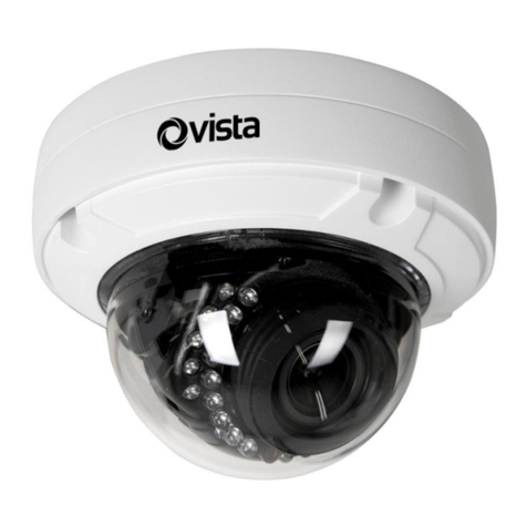
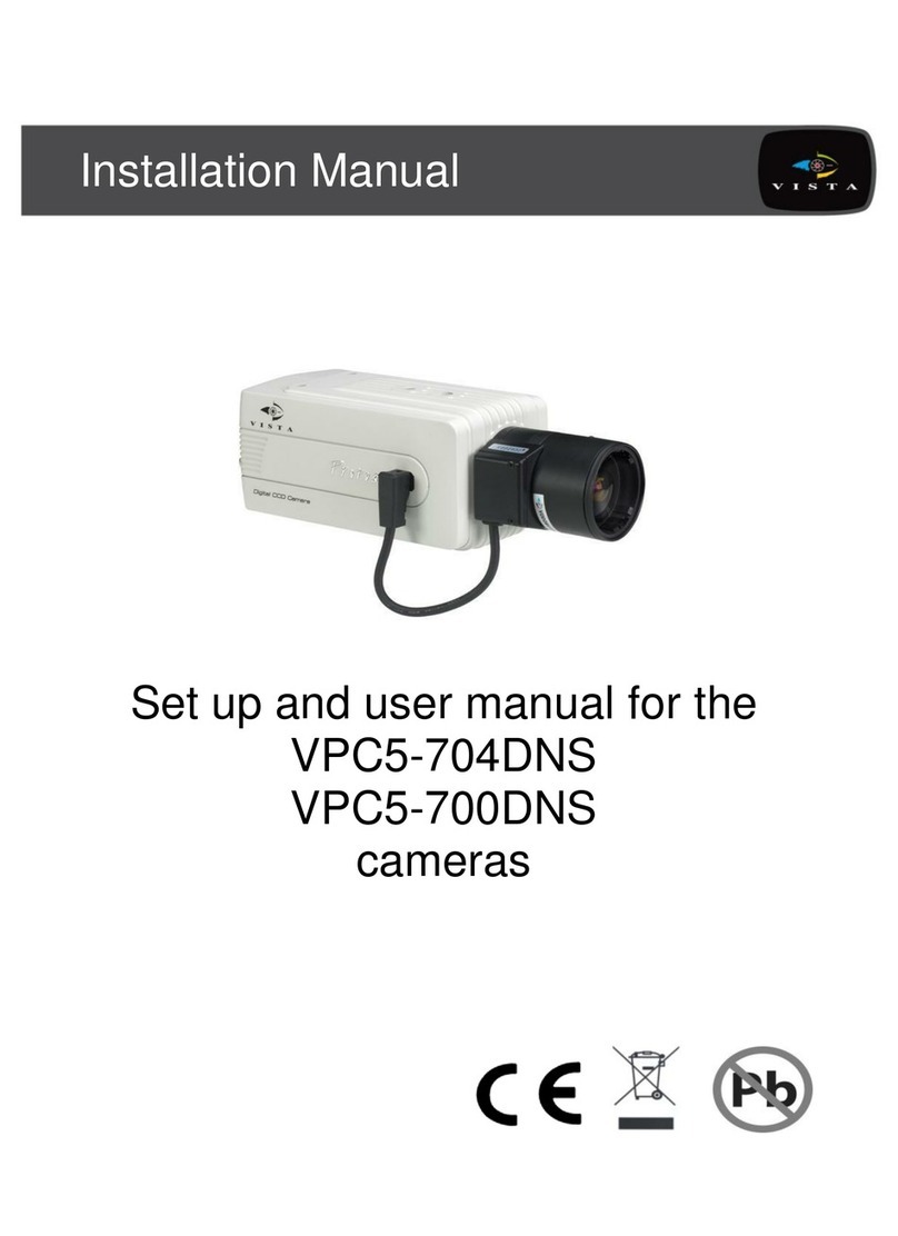
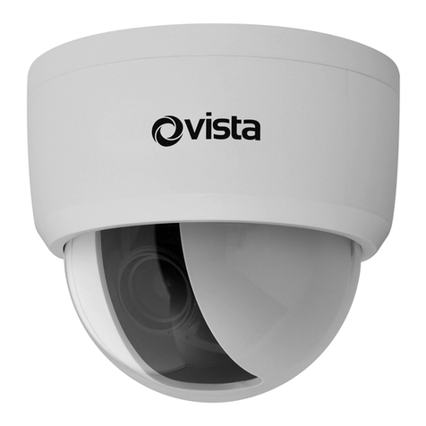
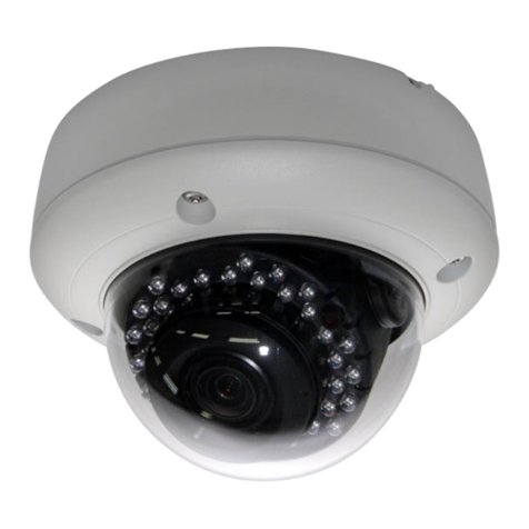
Vista VC200 Series Compact Cameras
Installation Instructions
PRODUCT SAFETY
This camera range is designed for use in general purpose CCTV applications and has no other purpose. Only operate your
camera between the temperatures of -10OC and +50OC. o not operate your camera outside its specified power supply range.
Cameras must only be used in clean, dry, dust-free environments unless housed in suitable protective housings to IP65 or better.
In order to avoid damaging the camera note the following point .
1. In tallation and ervicing i only to be carried out by uitably qualified and experienced per onnel.
2. Only power camera from a cla 2 i olated power upply.
3. Do not touch the image- urface of the en or. If the en or i accidentally touched, only clean it u ing i opropanol.
4. Do not expo e the en or to direct unlight a thi may impair the performance of the camera.
5. For outdoor u e, an appropriate protective hou ing conforming to IP65 or UL50 or better mu t be u ed.
ELECTROMAGNETIC COMPATIBILITY (EMC)
Thi i a cla A product. In a dome tic environment thi product may cau e radio interference in which ca e the u er may
be required to take adequate mea ure .
This product is intended solely for use in general CCTV applications.
The product must be installed and maintained in accordance with good installation practice to enable the product to function as
intended and to prevent problems. Refer to Norbain S Limited for installation guidance.
MANUFACTURERS DECLARATION OF CONFORMANCE
The manufacturer declares that the equipment supplied with this manual is compliant with the essential protection requirements
of the EMC directive 89/336 and the Low Voltage irective LV 73/23 EEC. Conforming to the requirements of standards EN 55022
for emissions, IEC801 parts 2, 3 and 4 for immunity and EN 60950 for Electrical Equipment safety.
CONTROLS AND SWITCHES
The diagram below shows the locations and functions of the controls and switches.
Mounting Bolt
Two 1/4 20 UNC mounting bolts are provided for mounting the camera, one on the the top of the case and one on the bottom of
the case.
Len Level Adu tment
If the camera is used with a direct drive ( ) lens this potentiometer varies the C reference voltage used to control the lens. The
potentiometer has the effect of increasing or decreasing the lens aperture. This potentiometer should be adjusted to obtain a 1V
pk-pk video output and is therefore the factory setting.
Compo ite Video
To obtain a 1.0V [pk-pk] composite video signal, connect a video coaxial cable terminated with a 75 Ohm BNC connector to the BNC
socket marked VI EO OUT.
Supply Terminal
These terminals accept a power supply of 12 V C ±10%, ripple less than 200mV.
EI on/off
The Electronic Iris (EI) compensates for excessive light level by automatically adjusting the shutter speed. The electronic iris
should be ON when using fixed or manual iris lenses. When using Auto Iris C lenses, the EI must be OFF. See also Lens Level
Adjustment. The default setting is ON.
ON
12
ON
12
BLC ON/OFF EI ON/OFF
COMPOSITE VIDE
