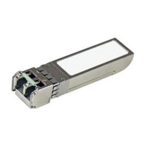
VISTEK V1679 User manual

1
VISTEK V1679SINGLE-MODE
FIBRE DATA TRANSCEIVER
USERGUIDE
www.pro-bel.com

VISTEK V1679 single-mode fibre
datatransceiver
2Issue 1
Contents
1. GENERAL..................................................................................................................5
2. GENERAL PURPOSE OUTPUTS.............................................................................6
2.1 Description.......................................................................................................6
2.2 Configuration...................................................................................................6
2.3 Output Specification........................................................................................7
3. GENERAL PURPOSE INPUTS.................................................................................8
3.1 Description.......................................................................................................8
3.2 Configuration...................................................................................................8
3.3 Examples for Driving V1679 GPI Inputs.......................................................10
3.3.1 Push Button or RelayDriven Switch....................................................10
3.3.2 N-Channel MOSFET Switch................................................................11
3.3.3 Open Collector Output........................................................................12
3.3.4 CMOS Output......................................................................................13
3.4 Input Specification.........................................................................................14
4. SERIALCOMMUNICATION PORTS.......................................................................15
4.1 Description.....................................................................................................15
4.2 Configuration Options...................................................................................16
4.2.1 RS-232/422 Mode Selection Jumper..................................................17
4.2.2 Slew-rateSelection Jumper (Slow/Fast).............................................17
4.2.3 Line Termination Jumper (RS-422 Only).............................................17
4.3 RS-232/422 Examples....................................................................................18
5. REAR PANEL CONNECTIONS...............................................................................21
5.1 Silkscreen Legend and Markings.................................................................21
5.2 ElectricalInterfaces.......................................................................................22
5.3 V1679 Breakout Adapter................................................................................23
5.3.1 Serial Communications Ports..............................................................23
5.3.2 GPIO Terminals..................................................................................24
5.3.3 Power SupplyOutput..........................................................................24
5.4 OpticalInterfaces...........................................................................................24
5.4.1 Optical Input........................................................................................24
5.4.2 Optical Output.....................................................................................25
5.4.3 Encoding Scheme and Data Rate.......................................................25
6. FRONT PANEL LED INDICATORS.........................................................................26
6.1.1 RemoteControl Access and Power Indicators....................................26
6.1.2 Carrier / Lock /Laser FailIndicators...................................................27
6.1.3 Serial Comms ActivityIndicators.........................................................27

VISTEKV1679single-modefibre
data transceiver
HU-V1679 3
7. DART INTERFACE..................................................................................................28
7.1 General...........................................................................................................28
7.2 DART Control Registers................................................................................28
7.3 DART Status Registers..................................................................................29
8. BLOCK DIAGRAM...................................................................................................30
9. CLEANING INSTRUCTIONS...................................................................................31

VISTEK V1679 single-mode fibre
datatransceiver
4Issue 1
The V1679 board isaClass1Laser Product under the Food and Drug Administration (FDA) / Center for
Devices and Radiological Health (CDRH) regulation. It cannot, undernormal operating conditions (i.e.,
intended use), emit ahazardouslevel of optical radiation. No warning label orcontrol measures are
required bythe FDA/CDRH. The IEC(International Electrotechnical Commission)standard(Publication
60825-1) requiresawarning label and specifiesthat classification be made under fault conditions.
Therefore, systemsthat are Class1under FDA/CDRH rules maynot necessarilybe Class1under the
IEC.
The Laser wavelengthsbeing used on V1679 boards mayrange from1310nmto 1610nm.The average
optical output powerdoes not exceed 0dBm(1mW)under normal operating conditions. Unused optical
outputsare automaticallycovered with a shutter and prevent direct exposure to the laserbeam.
Even though the powerofthese lasersis low, the beamshould be treated with caution and common
sense becauseit is intense and concentrated. Laser radiation can cause irreversible and permanent
damage of eyesight. Please read the following guidelinescarefully:
1. Makesure that afibre is connected to the board’sfibreoutputs beforepower is
applied. If afibre cable (e.g. patchcord)is alreadyconnected to an output, makesure
that the cable’s otherend isconnected, too, before powering up the board.
2. Do not lookin the end ofafibre to see iflight iscoming out. The laserwavelengths
being used (mostcommonly 1310nmand 1550nm)are totallyinvisible to the human
eyeand will causepermanent damage. Alwaysuse optical instrumentation, such as an
optical power meter, to verifylight output.
LASER SAFETY

VISTEKV1679single-modefibre
data transceiver
HU-V1679 5
1. GENERAL
The V1679 SINGLE-MODE FIBRE DATATRANSCEIVERSformpart of the VistekV1600 range offibre
interface products. Based on a 3U high baseboard, which iscommon to all members ofthe V1679 family, the
board can be fitted into a V1603 or V1606 rack, fromwhich it receivesitspower and control.
A passive rear module is required for all electrical and optical signal interconnections.
The V1679 module is fullycompatible with the VistekDARTremote control system.
Available V1679 models to date:
V1679/IO Provides8General Purpose, opto-isolated Inputs and 8General Purpose, earth-free Outputs.
All GP I/O'scan either be driven externallyor internally(DARTcontrolled). All Inputs can be
monitored byDART.
V1679/IP Provides16 General Purpose, opto-isolated Inputs,with the choice of8Inputsto be triggered
eitherexternally(Opto-IsolatorInput)orinternally(DARTcontrolled). All16 Inputs can be
monitored byDART.
V1679/OP Provides16 General PurposeOutputs, with the choiceof8Outputs to be either driven
externally,i.e. driven through acorresponding signal sent fromthe remote site via the fibrelink,
or internally(DARTcontrolled).
Common to all modelsare two independentlyoperating Serial Communication Ports, which can either be
configured to complywith RS-232 (single-ended)or RS-422 (differential) electrical standards.
NumerousRS-422 or RS-232 serial control applicationscan be now extended over long distances, with the
advantage of having an earth-free connection over fibre (no ground-loop problems) and negligible latency
(speed oflight!).
A good example for using the V1679'sRS-232 port is to remotelycontrol a V1606 Rack overa single-mode
fibre linkofup to 60kmlength.
With a wide choice of different CWDM Laserwavelengthsavailable, the V1679 fits seamlesslyin installations
with fibre links alreadyin operation.
Togetherwith the existing range ofAdvanced Fibre Interfaces (V1673/74 Series)and Passive Fibre
Distribution modules (V670xSeries), the V1679 adds anotherbuilding block to Vistek'stotal fibre solutions.

VISTEK V1679 single-mode fibre
datatransceiver
6Issue 1
2. GENERALPURPOSE OUTPUTS
2.1 Description
Depending on the actual board configuration, the V1679 supportsup to 16 General Purpose Outputs. Each
Output isimplemented as an earth-free, drycontact Relayswitch. Each switch can be configured to operate
either in a 'NormallyOpen' (short: NO) mode, orin a 'NormallyClosed' (short: NC) mode.
The Relayscan be identified aslittle black cubes, lined up in either one group (V1679/IO, Group B only) or
two groups(V1670/OP, Group A and B) at the rearconnector end of the board. The output configuration
Jumpers can be found in front ofeach Relay. Both Jumper positions(NC or NO)are clearlymarked on the
board's silk-screen. The factorydefault setting for each output is'NormallyOpen'.
A Relaywill change its state, i.e. itscontact will be closed (oropened, depending on the actual Jumper
position!), when either being triggered at the far end (remote site)bya state change ofthe corresponding
General Purpose Input, orlocallyvia DART.
The polarityofthe received control bit foranygiven output is application dependent, hence an unambiguous
relationship between input and output polarities doesn't exist. One might have to experiment with the NO/NC
Jumper settingsin order to get the output polarityright. In case ofa power failure however, the Relayswill fall
backinto their default state asconfigured bythe NO/NC Jumpersbecause theyare non-latching. The last
known 'good' state ofeach output willbe latched in case ofa broken transmission line or in case of
disconnecting the transmitter at the farend. The Outputswill resume switching assoon as the connection is
re-established. Note that the Relays are not suitable for switching high-current loadsor RF signals.
2.2 Configuration
Each relaywithin a group is clearly numbered (A1..A8 or B1..B8). Please see section 5.2 'Electrical
Interfaces' to find the corresponding signal pairsfor each output at the rear connector.
NormallyOpen /
Normally Closed
Jumper
B5
GPI Output
Group Name & Number
Relay
NC NO
Circuit Diagram
NC NO
GPIOn+
GPIOn-
Relay Contacts
Jumper
Board Layout
Rear Panel
Connections
Figure 1 : General Purpose Outputs (Circuit Diagram)

VISTEKV1679single-modefibre
data transceiver
HU-V1679 7
2.3 Output Specification
Number of Outputs:
V1679/IO: 8 Earth-free, drycontact Relayswitches
V1679/OP: 16 Earth-free, drycontact Relayswitches
Contact configuration: Normally Open (NO) or NormallyClosed (NC)
Contact material: Ag + Au Clad
Contact rating: 0.5A@ 24Vd.c. max.
Maximumoperate time: 5 ms
Maximumrelease time: 5 ms
Maximumbounce time: 6 ms

VISTEK V1679 single-mode fibre
datatransceiver
8Issue 1
3. GENERALPURPOSE INPUTS
3.1 Description
Depending on the actual board configuration, the V1679 supportsup to 16 General Purpose Inputs.
A V1679/IO features 8 General Purpose Inputsin addition to its8 GeneralPurpose Outputs, whereasa
V1679/IP comeswith 16 Inputsand no Outputs.
Each ofthe Inputs comprisesan Opto-Isolatorwith integrated Schmitt-Trigger Buffer, amongst other features,
such as:
• Jumper configurable on-board input biasing (+5V or +12V)
• Jumper configurable short to ground
• On-board, 100 Ohmcurrent limiting resistor for Opto-Isolator
• Reverse polarityprotection
• Wide input current range
• High speed (up to 1Mb/s)
Variousconfiguration optionsallow straightforward interfacing of the GP Inputs to a varietyof'driving'
sources'. Adriving source can be assimple asa push button, an 'Open Collector'output or a TTL/CMOS-
level bufferwith a current-sinking/sourcing capabilityofaslow as±4mA. Extra series resistorsmight be
required when using a voltage source of> 7V in order to limit the forward current ofthe EmitterDiode inside
the Opto-Isolator. Please checkwith your technical department or contact Vistekfora suitable solution.
Examplesof different interfacing techniques will be shown later.
3.2 Configuration
The following circuit diagramshowsthe input circuit ofeach General Purpose Input. Understanding the
diagramwill help in finding the proper configuration for a specificapplication.
100R
390R 1K8
GPIOn-
GPIOn+
+5V +12V
1N4148
Emitter Sectionof Opto-Isolator:
ForwardVoltageV
F:1.5V (max)@IF =10mA
Turn-On ThresholdCurrentI
F(ON):1.6mA(max)
Continous Forward CurrentIF:60mA(max)
InputBias Voltage SelectionJumper
Short toGND Jumper
Notes:
BoardGND=ChassisGND
Always provideaproper return-current pathforyour signal!
From/To 44-way High DensityD-TypeConnector
Protection Diode:
ForwardVoltageV
F: 1.0V (max)@IF = 10mA
On-board power supplies
Figure 2 : General Purpose Inputs (Circuit Diagram)

VISTEKV1679single-modefibre
data transceiver
HU-V1679 9
When driving the Opto-Isolator froman external voltage source, one must check that the forward current
through the Light Emitting Diode (LED) inside the Opto-Isolatordoesnot exceed 60mA. Otherwise, the Opto-
Isolator can be permanentlydamaged or even destroyed.
The current IFthrough the LED is determined bythe Input Voltage VIN supplied between a GPIOn+ and
GPIOn-connector pin pair, the forward voltage ofthe LED VFLED, the forward voltage of the protection diode
VF 1N4148 (which isin serieswith the LED), and the on-board 100Ohmcurrent limiting resistor. The reason for
having an extra protection diode isbecause ofthe relativelylow reverse (breakdown) voltage ofthe LED,
which is 6V (typ), compared to 75V(min)of a 1N4148 silicon diode. This makesthe GP Inputsfairly robust
against accidentally reverse biased input pins.
Byapplying Ohm's law, the forward current IFthrough the LED can be calculated asfollows:
Ω
+
−
=
100
)( 1N4148FLEDFIN
F
VVV
I
Considering the worst-case scenario, bytaking VF LED (min) and VF 1N4148 (min), VIN must not exceed 7.5V,
unless an extra current limiting resistor in seriesto the 100 Ohmis provided.
WARNING!
The maximum, continuous currentthrough the Opto-Isolator's LED mustnotexceed 60mA!
Using the on-board generated forward bias supplyfor the LED (+5V or +12V), the current through the LED is
limited to about 5mA. This means that driving an Input with an Open Collector Driver for instance, the Driver
must be capable of sinking at least 5mA!
The silkscreen on the PCBidentifies each Input byitsGroup Name (A orB) and itsnumber (1..8).
The configuration Jumpersforeach GP Input arelocated closelyto the corresponding Opto-IsolatorIC. The
Jumpers are positioned as follows:
Short-to-GND
Jumper
Opto-Isolator
5V 12V
A5
On-board
Input Bias Voltage
Jumper
GPI Input
Group Name & Number
BoardLayout
Figure 3 : General Purpose Input Jumper Locations

VISTEK V1679 single-mode fibre
datatransceiver
10Issue 1
3.3 Examples for Driving V1679 GPI Inputs
3.3.1 PushButton or RelayDriven Switch
A Push Button isa simple example ofhow a GPI Input can be driven. One should be aware that when using
anytype ofmechanicallyactuated switch, the input signal could bounce forseveral millisecondsbefore it
reachesa stable state. Thisimpliesthat the received bit at the farend ofthe fibre linkis unstable forthe
same period oftime.
The built in Schmitt-Trigger Bufferin the Opto-Isolator can only'tidyup' slow rising edges, but it cannot
suppress heavilybouncing input signals.
100R
390R 1K8
GPIOn-
GPIOn+
+5V +12V
1N4148
InputBias Voltage Selection Jumper
Short toGND Jumper
(short)
On-boardpowersupplies
Push ButtonSwitch
ormechanically
actuated Switch
(Relay)
Note:
TheLED ispermanently'ON'aslongasthePush-Buttonisopen.
Byclosingtheswitch, theLEDwill beshortedandgoes'OFF'.
Rear Connector SideBoardSide
Figure 4 : Example 1

VISTEKV1679single-modefibre
data transceiver
HU-V1679 11
3.3.2 N-Channel MOSFETSwitch
The mechanical switch shown in the previous example can easilybe replaced byan N-Channel MOSFET
Switch, as illustrated in the diagrambelow. Using a FETnot onlyeliminates possible bouncing problems,
which are common to most mechanical switches, it also allows much fasterswitching cycles. A bounce-free
output issubject to a 'clean' control signal applied at the FET'sGate input.
100R
390R 1K8
GPIOn-
GPIOn+
+5V +12V
1N4148
Input Bias Voltage Selection Jumper
Short toGND Jumper
(short)
On-boardpower supplies
Note:
The LED ispermanently 'ON' aslong astheFETisswitchedoff.
By applyingapositivevoltage between Gateand Source, higher thantheFET's
Gate-Source Threshold voltageVGS(th), the FETbecomesconductive andtheLED
goes'OFF'. ThemaximumDrain currentIDislessthan7mA.
Rear Connector SideBoard Side
G
D
S
Figure 5 : Example 2

VISTEK V1679 single-mode fibre
datatransceiver
12Issue 1
3.3.3 Open Collector Output
Open Collector Outputscan be found quite often in conjunction with GPI Outputs. Theyprovide a flexible way
of interfacing with 3rd partyequipment without the need ofmodificationsor for additional hardware.
Asfarasthe V1679 GPI Inputs are concerned, the following guidelinesapplywhen connecting to an Open
Collector Output:
• The Open Collector Output must be capable ofsinking at least 5mA(normally specified as ICor
CollectorCurrent).
• The Transistor must withstand at least 12V(minus the voltage drop acrossthe diodes, to be precise) in
the 'off' state (normallyspecified asVCE or Collector-Emitter Voltage).
• A ground (GND) connection between the remote control unit (Open Collector Output)and the V1679 is
essential.
100R
390R 1K8
GPIOn-
GPIOn+
+5V +12V
1N4148
Input BiasVoltage SelectionJumper
Short to GND Jumper
(open)
On-boardpowersupplies
Rear ConnectorSideBoardSide
BufferwithOpen Collector Output
Note:
Acommon GND connection between theremote control (Open Collector Output)
and the V1679 module(e.g. via dedicatedGNDPINonRear Connector) is
essential.
GND
Figure 6 : Example 3

VISTEKV1679single-modefibre
data transceiver
HU-V1679 13
3.3.4 CMOS Output
5VCMOSfamilieswith sourcing/sinking capabilities ofaslow as±4mA, such asHC orHCT, can be also
used to drive a V1679 GPI Input. In order not to violate the CMOS Buffer'soutput specification, an additional
current limiting resistor could be necessary. Ifthe Buffercan source -24mA, (AC, ACTFamilies), no
additional resistor isrequired since the on-board 100Ohmseriesresistor providessufficient current limiting.
100R
390R 1K8
GPIOn-
GPIOn+
+5V +12V
1N4148
Input Bias Voltage Selection Jumper
(open)
ShorttoGNDJumper
(open)
On-boardpowersupplies
Rear Connector SideBoardSide
Note:
Anextraseriesresistorisrequiredinorder tolimitthecurrent throughtheCMOS
Buffer tocomplywithitsspecification. NotethattheBuffer'soutput voltageinthe
highstate(V OH ) isonlyguaranteeduptoacertaincurrentlimitdrawnfromthe
output(IOH).
Asitcanbeseen inthediagram,usingaCMOSBuffer can beimplementedto
be'earth-free'(i.e.noGNDconnectionbetweenthecontrolunitandtheV1679's
GND), which meansnotroublecausedbygroundloopcurrents(which canprove
toberather difficulttocope with). However, cable-lengthandspeed restrictions
apply.Theslower theselectedCMOSoutputintermsofitsslewrate,thebetter!
GND
0
0
0
0
0
5VCMOSBUFFER
330R
Figure 7 : Example 4

VISTEK V1679 single-mode fibre
datatransceiver
14Issue 1
3.4 Input Specification
Number of Inputs:V1679/IO: 8 Opto-Isolators
V1679/IP:16 Opto-Isolators
Opto-Isolator Rating (TA=25°C):
Emitter(LED)ContinuousForward Current: 60mA
Input Forward Voltage VF:@ IF=10mA: 1.2V(typ), 1.5V (max)
@ IF=0.3mA: 0.75V (min), 1.0V (typ)
Turn-On Threshold Current IF(on):1.6mA (max)
Turn-OffThreshold Current IF(off):0.3mA (min), 1.0mA (typ)
Turn-On Time ton:4s (max)
FallTime tf:0.1µs (typ)
Turn-OffTime toff:4s (max)
Rise Time: tr:0.1µs (typ)
Data Rate (NRZ): 1.0MHz(typ)

VISTEKV1679single-modefibre
data transceiver
HU-V1679 15
4. SERIALCOMMUNICATION PORTS
4.1 Description
All V1679 modelshave two independentlyoperating Serial Communication Ports, named COM1 and COM2.
Both ports can be configured to complyeither with RS-232 (single-ended) or RS-422 (differential)electrical
standardsas specified bythe EIA (ElectronicsIndustryAssociation).
Free and useful RS-232/422/485 publications can be found on Analog Device's website (www.analog.com) or
on B&B Electronic'swebsite (www.bb-elec.com).
A highlyrecommended reading on the RS-232 interface standard isMaxim'sApplication Note 83
'Fundamentalsof RS-232 Serial Communications', which can be downloaded fromMaxim'swebsite
(www.maxim-ic.com).
Mode ofoperation, slew rate and an optional line termination (RS-422 only)can be configured bysetting
Jumpers accordingly.
Data transfer ratesofup to 1Mbpsin RS-232 mode and 10Mbps in RS-422 mode can be achieved. The
transmission length dependslargelyon the interface type (RS-232 or RS-422), the qualityofthe cable and
the data rate itself. In theory, RS-422 can go asfar as 4000 ft. @ 10Mbps. The single-ended RS-232
interface isgenerallyspeaking less robust and more susceptible to interference than itsdifferential
counterpart RS-422. With RS-232, typical cable lengthsat low data rates(9600kbaud) are about 50 ft. In
some cases, with the use of a special, high qualitycable, thislimit can be extended to asmuch as 150 ft.
The RS-422 receiversused on the V1679 are equipped with a failsafe circuitrythat guarantees a logichigh
receiver output when the receiverinputsare open orshorted. Furthermore, receivers and transmittersare
protected against wiring faults.

VISTEK V1679 single-mode fibre
datatransceiver
16Issue 1
4.2 Configuration Options
The following illustration showsthe position and meaning ofall COM1 and COM2 related configuration
Jumpers:
Slew-rate selection
Jumper
RS-232/422
Transceiver
Slow
COM1
Fast
RS232RS422
RS-232/422
Transceiver
Slow
COM2
Fast
RS232RS422
Term TermRS422 only!
RS-232/422selection
Jumper
120OhmTermination
Jumper
COM2example shown:
Mode:RS-422
Slew-rate:Fast
Termination:On
Important:
The 120OhmTerminationJumpermustnotbe installed when operatingthe serialportsin the RS-232mode!
Figure 8 : Serial Comms PortConfiguration

VISTEKV1679single-modefibre
data transceiver
HU-V1679 17
4.2.1 RS-232/422 Mode Selection Jumper
The Mode Selection Jumperisused to configure a port forRS-232 or RS-422 operation. The following
combinationsare supported:
COM1: RS-232 RxD/TxD, CTS/RTS
COM2: RS-232 RxD/TxD, CTS/RTS
COM1: RS-422 RxD/TxD only1
COM2: RS-422 RxD/TxD only1
COM1: RS-232 RxD/TxD, CTS/RTS
COM2: RS-422 RxD/TxD only1
COM1: RS-422 RxD/TxD only1
COM2: RS-232 RxD/TxD, CTS/RTS
COM1: RS-232 full Modemsupport (RxD/TxD, CTS/RTS, DSR/DTR)2
COM2: RS-232 RxD/TxD only1
Notes:
1. 'RxD/TxD only' meansdata transfer without hardware flowcontrol (i.e. no CTS/RTS, DSR/DTR status
lines). Data protocol must support e.g. Xon/Xoff scheme for high data rates.
2. For fullModemsupport, two control lines (DSR/DTR) are actually'borrowed' fromCOM2. In thismode,
COM2 can onlyoperate asRS-232 with RxD/TxD linesonly.
Factorydefault setting isRS-232 for COM1 and COM2.
4.2.2 Slew-rate Selection Jumper (Slow/Fast)
Slew-rate limiting (set Jumper to 'Slow')minimizesEMI and reducesreflections caused byimproperly
terminated cables, allowing error-free data transmission up to 250kbps. Disabling slew-rate limiting (set
Jumper to 'Fast') allowsthe Transceiverto transmit at data ratesup to 10Mbpsin RS-422 mode and up to
1Mbpsin RS-232 mode. Factorydefault setting is 'Slow' forCOM1 and COM2.
4.2.3 Line Termination Jumper (RS-422 Only)
At data rateshigher than 250kbps, is stronglyrecommended to terminate the RxD line pairin RS-422 mode
byshorting the 'Term' Jumper.
Note that the Termination Jumper must not be installed when a port isconfigured as RS-232.
Factorydefault setting is'No Termination' for COM1 and COM2.

VISTEK V1679 single-mode fibre
datatransceiver
18Issue 1
4.3 RS-232/422 Examples
Always wanted to extend the cable ofyour Serial PC Mouse byup to 60kms?
A Serial PC Mouse onlyrequiresRxD/TxD and CTS/RTS, hence the second port can be used forsomething
more useful. Although this is not a particular serious application, it showshoweasyit is to demonstrate the
V1679'sserial communication portswithout the need for a second PC or other bulkyRS-232 peripherals.
The best wayto wire it up isusing Vistek'sV1679 Breakout Adapter, which can be pushed onto the 44-pin
high densityD-type connector at the rear panel and givesinstant accessto both serial portsand all GPIO
lines.
Please note that a so-called 'Null-Modem' cable (RxD/TxD, CTS/RTS and DSR/DTR signals crossed over)is
required for the connection between the PC'sSerial Port and the V1679 at the 'far' end. Ifthe Serial PC
Mouse isequipped with a 9-pin Dsub connector, it can be directlyconnected via a gender-changer
(male/male) to eitherCOM1 orCOM2 at the V1679 sitting at the 'near' end.
V1679/xx V1679/xx
COM1
COM2
up to 60kmsingle-mode fibre
GPIO
COM1
COM2
GPIO
RS-232
Laser Tx
Laser TxPIN-TIA Rx
PIN-TIARx
Note:
The two fibre links shown in the diagramcan be replaced by a single fibre
cable when using WDM modules on boths ends for multiplexing/de-
multiplexing two distinct wavelengths (e.g. 1310nmand 1550nm).
Up to 16 GPIO's
Up to 16 GPIO's
60kmCable Extension for Serial PC Mouse
using two V1679 Fibre Data Transceivers
SerialPC Mouse
RS-232
Laptop computer
'Null-Modem' Cable
'Near-End' V1679'Far-End' V1679
Figure 9 : RS-232 Example 1

VISTEKV1679single-modefibre
data transceiver
HU-V1679 19
The example belowshows an installation in which a VistekV1606 rack is being remotelycontrolled over a
long distance. Since the DARTdongle (DIN 341) requires all modemcontrol lines, COM1 hasto be
configured for full modemsupport. If onlyone fibre linkisavailable, a WDM orCWDM module can be used
on each end formultiplexing/de-multiplexing two distinct laserwavelengths.
V1679/xx V1679/xx
COM1
COM2
DART
Dongle
RS-232
CAN
up to 60kmsingle-mode fibre
GPIO
V1606 Rack
(LocalSite)
V1605ControlPanel
CAN
V1606Rack
(RemoteSite)
COM1
COM2
GPIO
RS-232
Laser Tx
Laser TxPIN-TIARx
PIN-TIARx
DART
Dongle
Note:
Thetwo fibrelinks shown inthe diagramcan bereplaced byasingle fibre
cable whenusingWDMmodules on bothsends for multiplexing/de-
multiplexing twodistinctwavelengths(e.g. 1310nmand1550nm).
Up to16GPIO's
Up to 16GPIO's
V1606 RemoteControl Exampleusing
twoV1679 FibreDataTransceivers
Figure 10 :RS-232 Example 2

VISTEK V1679 single-mode fibre
datatransceiver
20Issue 1
Thisexample illustratesthe use oftwo V1679's for controlling camera tilt-heads through RS-422 at an
outdoorvenue. Assuming that onlyone fibre linkis available, a CWDM module is used for multiplexing/de-
multiplexing different laser wavelengths, in thiscase not onlyfromthe V1679's, but also froma V1673 Dual
Fibre Transmitter (/TT) and Dual Fibre Receiver(/RR)pair for the actual video linkbackto the control room.
V1679/xx V1679/xx
COM1
COM2
RS-422
upto50kmsingle-mode fibre
GPIO
COM1
COM2
GPIO
LaserTx
Laser TxPIN-TIA Rx
PIN-TIARx
Up to 16GPIO's
Up to 16 GPIO's
RS-422 Camera ControlExampleusing
twoV1679 FibreDataTransceivers
Camera2
Camera1
RS-422
(ControlPanels and Rack Enclosures are notshown inthis diagram)
V1673/RR V1673/TT
RS- 4 22
RS- 4 22
SDIIn
SDIIn
C
W
D
M
C
W
D
M
Laser Tx
Laser Tx
PIN-TIA Rx
PIN-TIA Rx
SDIOut
SDIOut
Note:
Each Laser Transmittermustemit adifferent CWDMwavelength!
To otherprocessingmodules
RemoteSite(e.g.Outdoor Venue)
Local Site(ControlRoom)
SDI@270Mb/s
SDI@270Mb/s
Control2Control1
Figure 11 :RS-422 Example
Table of contents
Popular Transceiver manuals by other brands
Vertex Standard
Vertex Standard VX-160U Service manual
Yaesu
Yaesu FT-290R II Technical supplement

TEXAS RANGER
TEXAS RANGER TR-936 owner's manual
FlexRadio Systems
FlexRadio Systems FLEX-6000 Signature Series quick start guide
Alinco
Alinco DJ-V17TFH instruction manual
SOMFY
SOMFY animeo IP installation guide
