Vita Vibe ASB36-80C User manual
ASB36-80C 36" Wide 82" Tall Stall Bar with Chin Up Bar
Assembly G ide
TM
Please read this g ide thoro ghly before beginning
assembly and follow each process step by step.
Note: Some steps may require two people.
Tools req ired for assembly and installation:
9/16" and 1/2" Wrench or Socket Wrench
Phillips Screwdriver
Tape Meas re
Power Drill with 7/32" and 1/8" Drill Bits
St d finder (for wood st d mo nting)
Model # ASB36-90C Shown
VITA VIBE
ASB36-80C
36" Wide 82" Tall Stall Bar
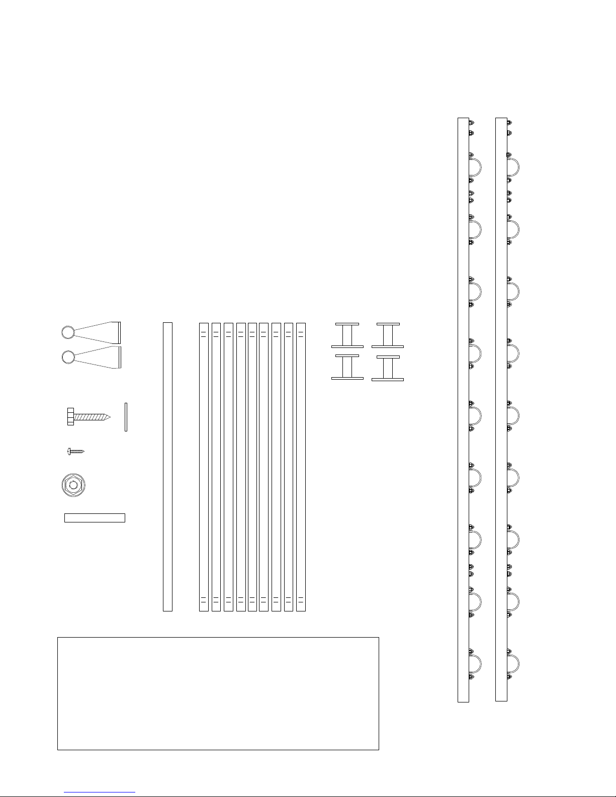
With Chin Up Bar Carton Contents.
A - 82" Stall Bar Upri ht Beams with Run Saddles & Hardware (Qty. 2)
B - Stall Bar Wall Mount Standoff Brackets (Qty. 4)
C - 1-1/2" Dia. Hardwood Ash Run s (Qty. 9)
D - 1-1/2" Dia. Hardwood Ash Chin Up Run (Qty. 1)
E - Chin Up Brackets (Qty. 2)
F - 5/16 x 2-1/2" La Bolt with Flat Washer (Qty. 8)
G - #10 X 3/4" Black Wood Screw (Qty. 4)
H - Decorative Bolt Head Cover Caps (Qty. 8)
I - Spacer Block (Qty. 1)
A
BCDE
F
G
H
Note: Some hardware items may include
additional pieces and are considered spares.
DISCLAIMER: As with any fitness or e ercise equipment, use of this
equipment should only be used by persons who are physically able to
use the equipment as it is designed for. Proper safety gear such as
padded mats, shoes, clothing and the like should always be used.
This equipment should not be used alone. Always have someone
nearby in case of an emergency. Vita Vibe, Inc. and it's affiliates will
not be liable for any injury or death resulting from use of this equipment.
User assumes responsibility for proper assembly, maintenance and
use of this equipment.
I
Spacer Block
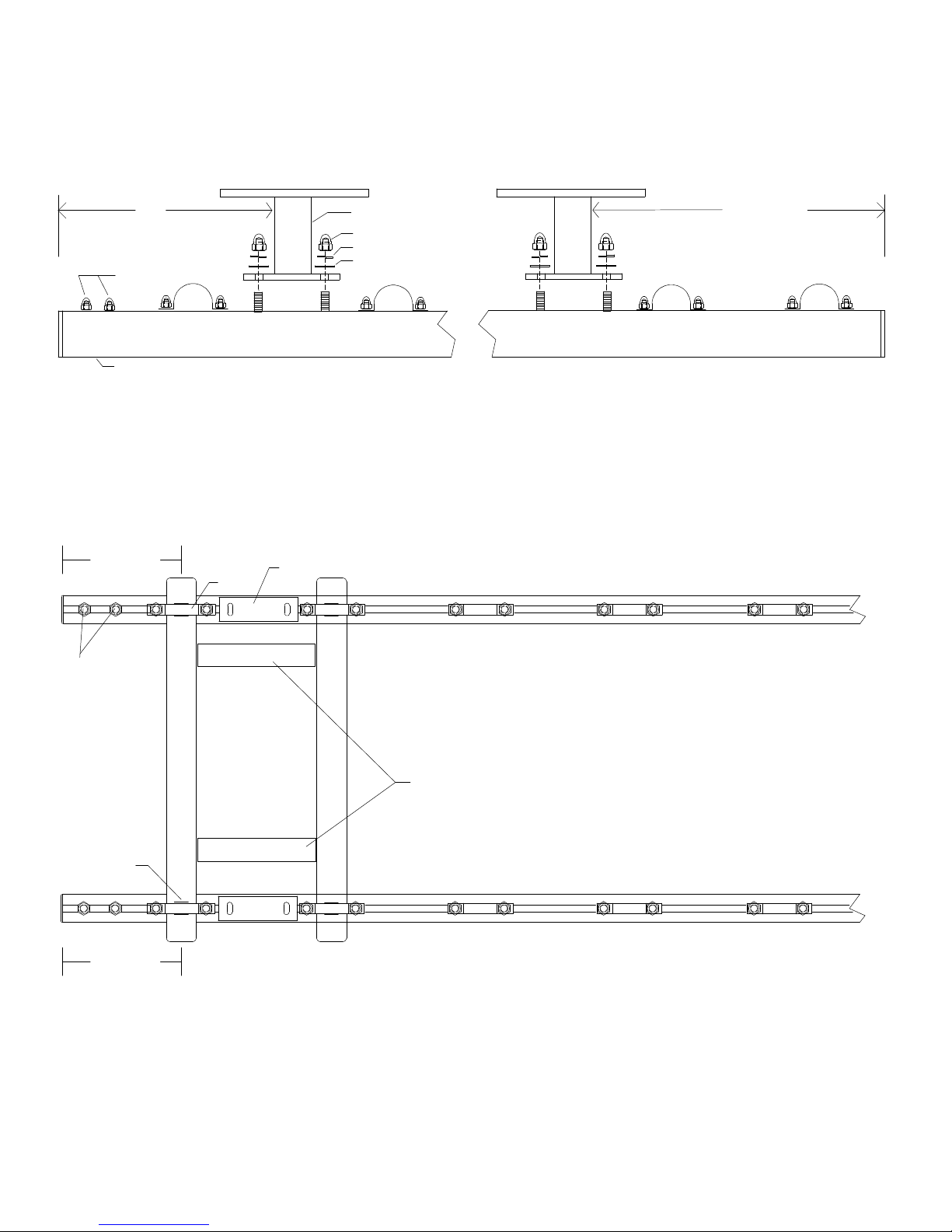
STEP 1
STEP 2
Attach the four wall mount standoff brackets (B) to the two upright beams (A) as shown by removing the pre-installed
acorn nuts and washers then placing the smaller side of the standoff bracket over the threaded bolts and re-installing
the washers and acorn nuts. DO OT TIGHTE UTS YET.
Measure 12" from the TOP end of the upright beam to the standoff bracket as shown below then securely tighten nuts.
Measure 17-1/2" from the BOTTOM end of the upright beam to the standoff as shown below then securely tighten nuts.
Attach the top rung (C)
Lay the two upright beams on the floor 32" apart. Loosen the acorn nuts on the top rung saddles enough to
insert the first wood rung. Position this wood rung under the top saddles locating the saddle between the
laser marks on each end of the rung. DO OT TIGHTE YET.
Measure 8-1/2" from the TOP of the upright beam to the CE TER of the wood rung as shown below.
Securely tighten saddle nuts.
STEP 3
TOP
12"
Reserved for
chin up bar
Acorn ut
Split Lock Washer
Flat Washer
Standoff Bracket
Upright Beam
TOP
17-1/2"
ASB3680C3
TOP
8-1/2"
8-1/2"
Reserved for
chin up bar
Attach the balance of rungs (C)
Once the top rung is in the correct position and securely tightened, begin attaching the rest of the rungs
working from the top to the bottom. Again, loosen the acorn nuts at each saddle enough to insert the wood
rungs. Position the wood rung under the saddles and locate the saddle between the laser marks at each
end of each rung. DO OT TIGHTE YET. Use the supplied wood spacer block to evenly space the
balance of the rungs by placing this spacer between the rungs as shown above. Once you have the rungs
spaced out you can then securely tighten the saddle nuts. ote: These instructions are for evenly spaced
rungs (8-1/2" center spacing) you can space the rungs to your desired location if you prefer.
Laser Marks
Standoff Bracket
Saddle
Spacer Block
Place the spacer block at both sides
when tightening saddle nuts.
Spacer Block
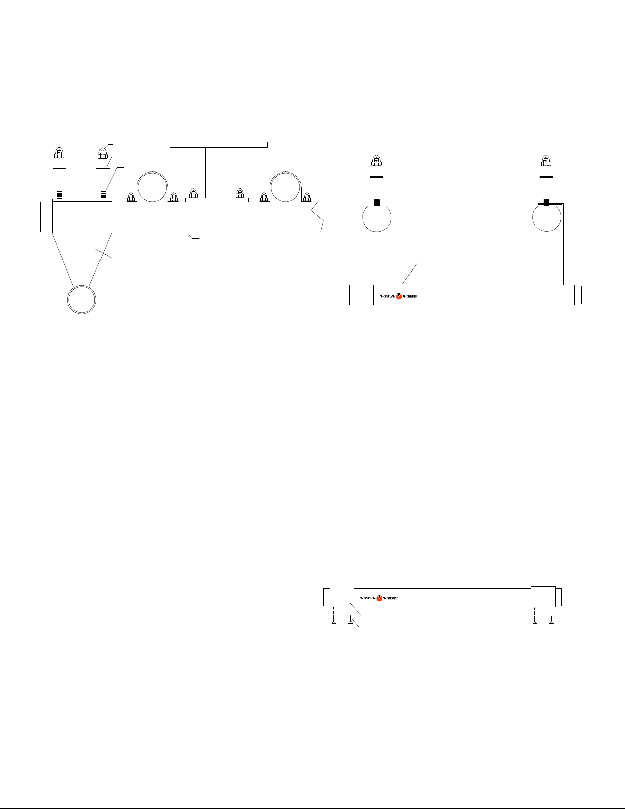
STEP 4
Attach the two chin up bar brackets (E) to the two upright beams (A) as shown by removing the pre-installed
acorn nuts and washers then placing the chin up bracket over the threaded bolts and re-installing
the washers and acorn nuts finger tight only. DO OT FULLY TIGHTE UTS YET.
Insert the wood chin up bar (D) into the chin up bar brackets as shown below. DO OT I STALL THE WOOD
SCREWS YET.
TOP
Upright Beam
ASB3680C4
Chin Up Bracket
Acorn ut
Flat Washer
Flat Washer
Mounting the assembled stall bar.
If assembled correctly, the wall mount standoff brackets will be spaced 32" apart allowing it to mount to standard
wood wall studs that are typically spaced 16" on center. once you have located your wood studs and with the help
of another person, stand the stall bar up against the wall and mark the spots where the stall bar will be bolted to
the wood studs. Pilot drill these eight locations with a 7/32" drill bit. OTE: If you are not experienced in doing
this type of work you may want to consult a handyperson or professional for help. There is the possibility of
utilities within the wall that you will want to avoid.
Securely fasten stall bar to the wall with the supplied 5/16" x 2-1/2" lag bolts and washers (F)
If mounting to a metal stud wall you will need to first mount wood blocking spanning at least 3 studs for both
upper and lower wall mount brackets. If mounting to a concrete or masonry wall you will first need to install
lag shield anchors or other type of 5/16" min. anchor bolts. After all bolts are installed push on the supplied
decorative bolt head cover caps (H) If mounting to a metal stud wall, you will need to securely attach two
backer / blocking boards to the metal stud wall then attach the stall bar as described above.
TOP TOP
ote: Mount chin up brackets
to the outside of upright beams.
Chin Up Bar (D)
STEP 5
ow that the stall bar is safely mounted to the wall, Adjust the chin up bar brackets to your desired height and securely
tighten both acorn nuts on both sides. Center the wood chin up bar between the two chin up bar brackets.
Pilot drill a 1/8" hole through the holes found on the bottom of each collar into the wood chin up bar and install the
supplied #10 x 3/4" black wood screws (G) (two per collar)
STEP 6 (Final)
Chin up bar collar
#10 x 3/4" Black wood screw
Equal Distance
To keep you new stall bar in top condition you may periodically treat the wood rungs with a light coat of Danish oil
or Linseed oil. Typically twice a year will suffice. Before each use please make sure all fasteners are tight and secure.
Vita Vibe, Inc. 40 Ellwood Ct. Greenville, SC 29607
Tel: 864-288-8934 Fax: 864-751-6302
Email: getfit@vitavibe.com
Please keep this assembly guide for future reference. Should you need assistance
with assembly or replacement parts contact us directly. Do not return to place of purchase.
Made in USA
Table of contents
Other Vita Vibe Fitness Equipment manuals


