Vital Home Systems VHS-1060 User manual

© Copyright 2016 Vital Home Systems
Vital Home SystemsTM
Wireless Control Panel
Model: VHS-1060
Wireless Control Panel Manual
Manual V 6.0 Dated 10/09/2016

P a g e | 1
© 2015 - 2016 Vital Home Systems, LLC
Table of Contents
Wireless Control Panel Control Panel Overview........................................................................2
I. Identifying Parts on the Wireless Control Panel...............................................................2
II. The Power Supply..............................................................................................................3
III. How to Install the Wireless Control Panel.......................................................................3
V. Getting Started ..................................................................................................................3
Programming the Wireless Control Panel...................................................................................3
Wireless Control Panel Local Programming Quick Reference Chart......................................3
How to Use Programming Mode.................................................................................................3
To Enter Programming Mode ......................................................................................................4
Storing Phone Numbers........................................................................................................4
Changing Phone Numbers....................................................................................................4
Clear Phone Numbers ...........................................................................................................4
Range Testing........................................................................................................................4
Exit Programming Mode........................................................................................................5
Reset Wireless Control Panel to Default Settings...............................................................5
Operation ...............................................................................................................................5
Fault Situations......................................................................................................................5
FCC Compliance Statement..........................................................................................................6
LED CONDITION –QUICK REFERENCE..............................................................................7
Sensor and Valve Zones.................................................................................................................8
Vital Home Systems Limited Warranty ......................................................................................9

P a g e | 2
© 2015 - 2016 Vital Home Systems, LLC
1
3
Wireless Control Panel
Overview Model: VHS-1060
I. Identifying Parts on the Wireless
Control Panel
FRONT VIEW
Green/Red LED – Power Indicator
Green indicates the Power Status.
Green LED ON indicates Power ON.
Green LED flash indicates AC failure.
RED indicates Program / Learn / Range Test
Mode.
Red LED ON indicates Program / Learn Mode.
Red LED flash indicates Range Test Mode.
Green –Cellular Signal Indicator
LED OFF indicates not connected to Cellular
network.
Green LED ON indicates Wireless Control Panel
connected to cellular network
Yellow LED –Fault Indicator
The Yellow LED will light up when any fault
situation is detected, then turn off when all
fault conditions are restored.
NUMERIC KEY
SET KEY
Press this key for setting the telephone
numbers.
CLR KEY
Press this key to exit Program Mode and return
to Normal Mode.
7
TEST KEY
While in Program Mode, press this key to enter
TEST Mode.
8
ACK KEY
Press this key to stop the voice Alarm after
alarm is sounded and it will stop the SMS from
going out if pressed prior to voice alarm. This
key may also be used for deleting a digit,
canceling the selection, aborting the current
application and returning to the Normal Mode,
etc.
It may also be used to stop playing the local
voice message.
When there is Fault situation indicated by
Yellow LED ON, pressing “ACK” will play the
corresponding voice message for 30
seconds or till CLR is pressed.
When there is no Fault, pressing “ACK” will
give no response.
# KEY
Press this key to dial #
KEY
Press this key to delay dial for three (3) seconds
Speaker
SMS LED –Flashes Red when sending SMS from
Wireless Control Panel
Side and Rear Views
Power –5V Micro USB Jack and Battery Switch
DC 5V Micro USB and Battery Switch cover.
Wall Mounting Bracket
4
5
6
8
9
2
123
456
789
0
*#
SET
CLR
TEST
AC K
13
13
14
14

P a g e | 3
© 2015 - 2016 Vital Home Systems, LLC
II. The Power Supply
An AC power adapter is required to connect to a
wall outlet. Only use the supplied DC 5V output and
micro USB adapter with the Wireless Control Panel
control panel.
Activating Rechargeable Backup Battery
In addition to the adapter, an internal
rechargeable battery in the Control Panel will
serve as a backup in case of a power failure.
During normal operation, the AC power
adapter supplies power to the Control Panel
and recharges the battery with the battery
switch in the ON postion
To charge the battery and have the battery
supply backup power in the event of a power
loss, remove the rubber battery switch cover
and slide the battery switch to “ON” with a
When the battery is fully charged, it can
provide back-up power for a period of at least
7 hours of standby time: It takes
approximately 48 hours to fully charge the
battery.
III. How to Install the Wireless Control
Panel
The easiest way to get to know the system and get
it up and running quickly is to place all the devices
and accessories programmed on a tabletop before
locating and mounting them.
The Wireless Control Panel can be mounted on the
wall or wherever desired. Make sure that the
Wireless Control Panel is positioned at
approximately chest height, so that the display may
be easily seen and the keypad will be convenient to
operate.
Using the Wall Mounting Bracket as a
template, mark the positions of the two (2)
holes.
Drill the holes, then install the screws and
dowels provided.
Place the Wireless Control Panel unit onto the
Wall Mounting Bracket, with the front facing
towards you.
V. Getting Started
Power supplied by an external 5V DC power
adaptor: Two (2) beeps are emitted and the Power
LED Green flashes ON indicating that it has entered
Normal Mode.
Continue to program the unit as instructed in next
section.
Programming the Wireless
Control Panel
All programming and pairing of devices with the
Wireless Control Panel control panel sensors and
VC100 valve controller may be done the Vital Home
Systems PC software. The software may be
downloaded from Vital Home Systems Website at:
http://www.vitalhomesystems.com/#!resources/c9ds
You must register your Wireless Control Panel on the
Vital Home Systems Website to download the
software.
The Software is written only for Windows version 7
through Vista. Download and install the software to
your Windows Desktop prior to plugging the
Wireless Control Panel USB cable into the computer
and the Wireless Control Panel Control Panel. Please
see the software manual for programming
Wireless Control Panel
Local Programming Quick
Reference Chart
Wireless Control Panel in Normal mode Commands
Function
Keypad operation
Enter program mode
SET + # + (pin code) + SET
Clearing alarms
ACK Key
Commands while in Wireless Control Panel Program mode
Function
Keypad operation
Set phone number
SET + (1~10) + # + (phone
number) + SET
Clear phone number
SET + (1~10) + SET
Test phone number
TEST + (1~10) + SET
Cold Water Valve ID(01~64) close
SET + 20 + # + (1~64) + SET
Hot Water Valve ID(01~64) close
SET + 20 + # + (1~64) + * + SET
Cold Water Valve ID(01~64) open
SET + 21 + # + (1~64) + SET
Hot Water Valve ID(01~64) open
SET + 21 + # + (1~64) + * + SET
Disable Auto Water Shutoff feature
SET + 30 + SET
Enable Auto Water Shutoff feature
SET + 31 + SET
Water sensor & Valve Range Test
TEST + 80 + SET
Pin code (passcode) change
SET + 90 + # + (pin code) + SET
How to Use
Programming Mode
The Wireless Control Panel may also be programmed
for certain functions locally on the control panel
face. See the next section how to program the
Wireless Control Panel locally.

P a g e | 4
© 2015 - 2016 Vital Home Systems, LLC
NOTE! You may only connect sensors and VC100
Valve controllers to the Wireless Control Panel with
the Vital Home Systems Windows PC Software.
To Enter Programming
Mode
Step 1. With the Wireless Control Panel in Normal
Mode, press “Set” key
Step 2: Press “#” Key
Step 3: Enter Pin Code
The Pin code consists of a 4-digit number.
Factory default is “0000”.
Step 4: Press “Set” key. A long beep is emitted and
Power LED lights ON Red.
NOTE:
Under Program Mode, a key-press interval
of five (5) seconds is allowed; the process
will abort automatically if the time is
exceeded, or incorrect entry is made. A
quick four (4)-beep sound will be emitted,
indicating Program exit Mode and return to
Normal Mode.
Once in Program Mode, if a key is not
pressed for 30 minutes. The Wireless
Control Panel will sound five (5) quick-
beeps, then automatically exit Program
Mode and return to Normal Mode.
To enter Program Mode, return to Step 1.
You may press “CLR” key anytime to exit
Program Mode and return to Normal Mode.
Under Programming Mode, you may perform the
following settings:
Open or Close the VC100 Valve Controller
Storing, change, or remove Telephone
Numbers
Disable or Enable auto water shut
automatic valve operations
Range Testing for valves and sensors
Storing Phone Numbers
Step 1: With Wireless Control Panel already set to
Programming Mode, press “SET” key.
Step 2: Select your Dialling Priority Order Number 1
through 6. Then press the “#” key.
NOTE:
A maximum of five (5) CELL PHONE
NUMBERS ONLY numbers may be stored in
priority order. You may store less than five
numbers.
1, 2, 3, 4, and 5 represent the priority
number of the five telephone numbers
respectively.
The Wireless Control Panel will
automatically dial in sequence of the stored
cell phone numbers.
Step 3: Key in phone number (maximum 20 digits),
then follow by the “SET” key to complete entry.
NOTE:
The “*” may be used to delay dialing for
three (3) seconds. If more delay time is
required, pressing an additional “*” will
allow an additional three second delay
time. You may press “*” as often as
required.
Changing Phone Numbers
To change the telephone numbers, follow the steps
in Storing Telephone Numbers described in previous
section, then enter the new telephone numbers.
This will override the numbers previously
programmed.
Clear Phone Numbers
To delete the telephone numbers, follow the steps
as in Storing Telephone Numbers described in
previous section and press “SET” without entering
any new phone numbers.
SET + 1~6 + SET
Successful deletion is indicated by a long beep,
followed by Power LED Red lights ON.
NOTE:
For Storing, Changing or Removing
telephone numbers, a key-press interval of
five (5) seconds allowed.
If time is exceeded, or an entry is made in
error, the unit will automatically abort the
process and emit quick four (4) beeps,
indicating return to Program Mode.
To exit Programming Mode and return to
Normal Mode, press “CLR” key.
Range Testing
Step 1: With the Wireless Control Panel in
Programming Mode, press “Test” key followed
by “8 then 0 then Set.”
The Power LED Red will flash, indicating that it
has entered Range-Test Mode.
Step 2: Press Sensor Test button. The Power LED
Red flashes ON for one (1) second then a long
beep will sound, indicating that signal has been
successfully received at this distance range.

P a g e | 5
© 2015 - 2016 Vital Home Systems, LLC
The Wireless Control Panel LED will also flash
ON, enabling the person testing the range from
afar to see the condition in case the beep
cannot be heard.
NOTE:
Once a sensor has been successfully
Learned-In, the Wireless Control Panel LED
will stay lit for another 60 seconds to allow
you to Learn-In the next one.
Once in Range-Test Mode, if a key is not
pressed for 30 minutes, the Wireless
Control Panel will sound five (5) quick-
beeps then automatically exit Range-Test
Mode and return to Program Mode.
You may exit Range-Test Mode to return to
Programming Mode anytime by pressing
“CLR” key.
To exit Programming Mode and return to
Normal Mode, press “CLR” key.
To enter Range-Test Mode, return to
Step 1.
Exit Programming Mode
Press “CLR” key to exit the Programming Mode and
return to Normal Mode.
Reset Wireless Control Panel to Default
Settings
Step 1: Remove all power sources, including AC
power adaptor and battery. (To remove the
battery remove the 4 black feet and unscrew
the 4 case screws. Be careful not to over
tighten the screws when putting back together
so as not to strip the screw holes. Unplug the
battery from the PC board).
Step 2: With the panel apart keeping the “CLR” key
pressed, plug in the AC power adaptor. A long
one-second beep will emit indicating that the
Panel has been successfully reset to Default
Settings.
Step 3: Plug the battery back in and close the case
carefully not to over tighten the screws.
NOTE:
Under Factory Default Setting –
PIN code is set as “0000”
Wireless Control Panel is cleared of all
telephone numbers.
Wireless Control Panel is cleared of all
sensor devices.
Operation
IMPORTANT NOTICE TO USER: The installation of
any water detection or automatic water shut off
system does NOT guarantee water will be detected
on all occasions or circumstances. Due to the
variety of environments the system can be
installed, how it is maintained and types of
installation, Vital Home Systems does NOT
guarantee or warrant against water or property
damage as a result of or/with the use of this
system.
Upon receiving the signal from the Water Sensors or
VC100, the Wireless Control Panel will flash the
Wireless Control Panel POWER LED and play the
appropriate message for specific event and time
period.
NOTE:
For VC-100 / AWS/TWS, it will play
appropriate voice message locally for 15
seconds before dialing out.
If two or more sensors are triggered one
after another, the corresponding messages
will be played in rotation.
After the Audio is played the SMS messages
will begin to be sent from the Wireless
Control Panel
If no telephone number is stored, the
Wireless Control Panel will not send SMS
reports
When two or more telephone numbers are
stored, the Wireless Control Panel will send
SMS reports in accordance to the Priority
Order number.
If prior to or during voice alarm playback,
the Wireless Control Panel receives a
disarm signal via SMS or when its “ACK” key
is pressed, the Wireless Control Panel
Power LED stops blinking and the Wireless
Control Panel stops the reporting.
The Wireless Control Panel phone numbers
entered are to be for cell phone numbers
only for SMS receipt
Fault Situations
The Yellow LED (Fault LED) will flash ON if the VHS-
Wireless Control Panel or any of the Learned
devices have a fault such as are disconnected or in a
continual low-battery status.
The Yellow LED will turn OFF automatically
once all of the faulty conditions are
restored, or faulty devices are removed via
the software.

P a g e | 6
© 2015 - 2016 Vital Home Systems, LLC
FCC Compliance Statement
Information for the U.S. Users:
FCC part 15:
This device complies with part 15 of the FCC Rules. Operation is subject to the following two conditions:
(1) This device may not cause harmful interference, and
(2) This device must accept any interference received, including interference that may cause undesired operation.
This equipment has been tested and found to comply with the limits for a Class B digital device, pursuant to part 15 of the FCC Rules. These
limits are designed to provide reasonable protection against harmful interference in a residential installation. This equipment generates,
uses and can radiate radio frequency energy and, if not installed and used in accordance with the instructions, may cause harmful
interference to radio communications. However, there is no guarantee that interference will not occur in a particular installation. If this
equipment does cause harmful interference to radio or television reception, which can be determined by turning the equipment off and
on, the user is encouraged to try to correct the interference by one or more of the following measures:
—Reorient or relocate the receiving antenna.
—Increase the separation between the equipment and receiver.
—Connect the equipment into an outlet on a circuit different from that to which the receiver is connected.
—Consult the dealer or an experienced radio/TV technician for help.
CAUTION: Changes or modifications not expressly approved by the party responsible for compliance could void the user’s authority to
operate the equipment. This equipment should be installed and operated with a minimum distance of 20 centimeters between the
radiator and your body.

P a g e | 7
© 2015 - 2016 Vital Home Systems, LLC
LED CONDITION – QUICK REFERENCE
Event
Power LED
4G LED
Green
SMS LED
Red
Fault LED
Yellow
GREEN
RED
Normal Mode
ON
OFF
Green
OFF
OFF
AC Fail and on Battery
ON Flashing
OFF
Green
OFF
OFF
Receive Alarm Event without “ACK”
ON
Flash (if AC fail)
OFF
Green
OFF
OFF
Fault Condition
ON
Flash (if AC fail)
OFF
Green
OFF
ON
SMS Sending
ON
Flash (if AC fail)
OFF
Green
Flash Red
ON
Programming Mode
OFF
ON
Green
OFF
OFF
Range Test Mode
OFF
Flash
Green
OFF
OFF
No Cellular Connection
ON
Flash (if AC fail)
OFF
OFF
OFF
OFF
Fault condition
ON
Flash (if AC fail)
OFF
Green
OFF
ON
P a g e | 8
© 2015 - 2016 Vital Home Systems, LLC
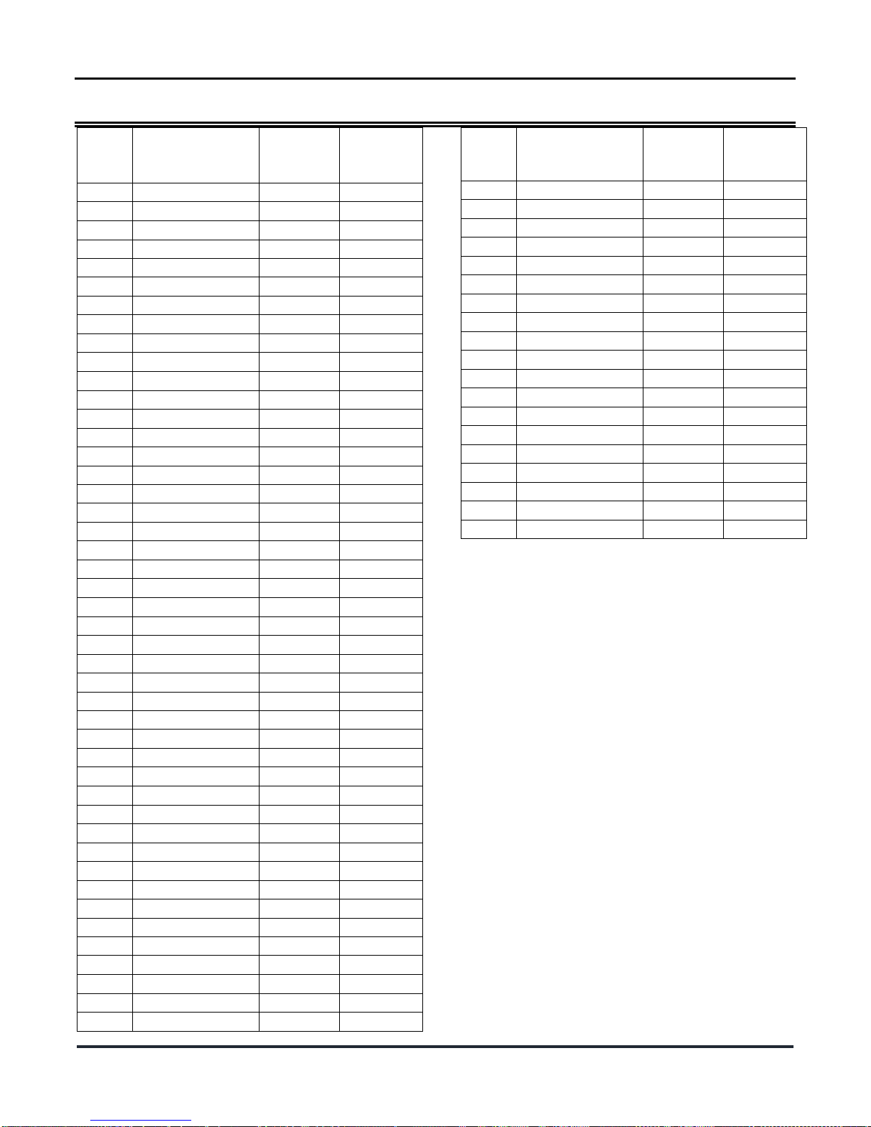
Sensor and Valve Zones
Sensor
ID
Zone Name
Cold
Water
Valve ID
Hot Water
Valve ID
1
AC Unit 1
01
1A
2
AC Unit 2
02
2A
3
AC Unit 3
03
3A
4
Bar Sink 1
04
4A
5
Bar Sink 2
05
5A
6
Bath Sink 1
06
6A
7
Bath Sink 2
07
7A
8
Bath Sink 3
08
8A
9
Bath Sink 4
09
9A
10
Bath Sink 5
10
9A
11
Bath Sink 6
11
11A
12
Bidet 1
12
12A
13
Bidet 2
13
13A
14
Bidet 3
14
14A
15
Bidet 4
15
15A
16
Coffee Maker
16
16A
17
Dehumidifier 1
17
17A
18
Dehumidifier 2
18
18A
19
Dishwasher 1
19
19A
20
Dishwasher 2
20
20A
21
Humidifier 1
21
21A
22
Humidifier 2
22
22A
23
Ice Maker 1
23
23A
24
Ice Maker 2
24
24A
25
Kitchen Sink 1
25
25A
26
Kitchen Sink 2
26
26A
27
Laundry Sink 1
27
27A
28
Master Bath Sink 1
28
28A
29
Master Bath Sink 2
29
29A
30
Master Toilet 1
30
30A
31
Master Toilet 2
31
31A
32
Refrigerator 1
32
32A
33
Refrigerator 3
33
33A
34
Shower 1
34
34A
35
Shower 2
35
35A
36
Shower 3
36
36A
37
Shower 4
37
37A
38
Shower 5
38
38A
39
Shower 6
39
39A
40
Toilet 1
40
40A
41
Toilet 2
41
41A
42
Toilet 3
42
42A
43
Toilet 4
43
43A
44
Toilet 5
44
44A
45
Toilet 6
45
45A
Sensor
ID
Zone Name
Cold
Water
Valve ID
Hot Water
Valve ID
46
Tub 1
46
46A
47
Tub 2
47
47A
48
Tub 3
48
48A
49
Tub 4
49
49A
50
Tub 5
50
50A
51
Tub 6
51
51A
52
Washing Machine 1
52
52A
53
Washing Machine 2
53
53A
54
Water Appliance 1
54
54A
55
Water Appliance 2
55
55A
56
Water Appliance 3
56
56A
57
Water Filter 1
57
57A
58
Water Filter 2
58
58A
59
Water heater 1
59
59A
60
Water heater 2
60
60A
61
Water Heater 3
61
61A
62
Water Main
62
62A
63
Water Soft 1
63
63A
64
Water Soft 2
64
64A

P a g e | 9
© 2015 - 2016 Vital Home Systems, LLC
Vital Home Systems Limited
Warranty
This Limited Warranty shall apply to items
manufactured sold or distributed by Vital Home
Systems LLC (“VHS”) that include the VHS and/or
VHS wholly-owned or partially-owned brands or
subsidiaries and were purchased from VHS or an
authorized VHS distributor or reseller directly by the
end user of the item (Customer).
VHS LIMITED WARRANTY AND LIABILITY
The Vital Home System is an advanced design in
water detection; it does not offer guaranteed
protection against a water event, water damage, or an
emergency. Any controls system, whether
commercial or residential, is subject to compromise
or failure for a variety of reasons, including, but not
limited to, installer or operator error.
Therefore, Vital Home Systems LLC does NOT
WARRANT or REPRESENT water damage will not
occur through the purchase or installation of this
system. NOR IS VITAL HOME SYSTEMS LIABLE
FOR WATER DAMAGE OR ANY OTHER DAMAGE
AS A RESULT OF THE USE OR INSTALLATION OF
ITS PRODUCTS.
VHS hereby represents and warrants that original
items manufactured (hardware), sold (embedded or
downloaded software), or licensed (external software)
by VHS and supplied to Customer for use, (hereafter
known as “Product”) shall be free from significant
defects in material and workmanship and will
reasonably conform to applicable specifications and
drawings, each subject to normal use and service as
set forth in the Product Limited Warranty Period
section of this agreement (the “Limited Warranty”).
This Limited Warranty is applicable when Product is
installed and used under normal conditions and in
accordance with the operating instructions, pursuant
to the Terms and Conditions set herein.
The sole and exclusive remedy of Customer for a
breach of any of the foregoing warranties shall be
limited, at the option of VHS, to either the repair or
replacement of any defective or non-conforming
component of the Products. Replacement Products or
parts may be new or reconditioned. Such remedies
shall be available to Customer only if VHS is notified
in writing within the applicable Limited Warranty
Period and is provided with a reasonable opportunity
to cure such breach.
Products under warranty will be repaired or replaced
at no charge to Customer, excluding shipping, with
the exception of any issues or damage caused by the
unauthorized repair by any and all third-party repair
houses, which will be subject to repair or replacement
charges as determined by VHS. Products repaired or
replaced while under warranty are warranted for the
remainder of the original Product Limited Warranty or
for a period of sixty (60) days from the date of repair
or the date of return shipment to Customer, whichever
is longer.
This Limited Warranty only applies to the Customer
as defined herein, and shall be of no force or effect if
Product is sold or transferred.
INSTALLATION TO BE WARRANTED BY INSTALLER
If VHS provides installation services, VHS hereby
warrants that all Services shall be performed in a
professional and workmanlike manner. VHS will re-
perform those Services that the parties mutually
determine to be defective at VHS’s expense provided
that VHS receives notice thereof within sixty (60) days
of performance of the Services.
VHS upholds a very high standard of execution.
Understanding that conditions affecting Product
repair or replacement may be beyond VHS’s control,
including vendor and/or manufacturer
discontinuation, market-affecting conditions, and
those conditions listed in the Limitation of Warranty,
VHS strives to make all commercially reasonable
efforts to assist our Customers towards the best
possible outcome.
VHS DOES NOT warrant or represent services
provided by its distributors, resellers or other third
party installer directly or indirectly contracted by the
customer to install VHS products.
PRODUCT LIMITED WARRANTY PERIOD
The Limited Warranty Period for Products
manufactured or produced by VHS and supplied to
Customer for use is one (1) year. The Limited
Warranty Period begins on the date of purchase by
the Customer and a completed Warranty Registration
Card is submitted at Vitalhomesystems.com.
Software is limited to a one (1) year warranty subject
to applicable license agreements. Products not
manufactured by VHS will carry the warranty and
related terms and conditions of the original
manufacturer (see Limitation of Warranty section).
If you have questions regarding technical support and
eligibility, please contact VHS customer service.

P a g e | 10
© 2015 - 2016 Vital Home Systems, LLC
PRODUCT WARRANTY AND SERVICE
VHS guarantees that Products under warranty will be
replaced at no charge within the first sixty (60) days
from the date of written or electronic notification if the
Customer experiences a service-affecting failure.
Return of the defective unit to VHS will be at
Customer expense.
In order to obtain warranty coverage, Customer must
first contact VHS’s Technical Assistance Center
(“TAC”) by phone or email. TAC will ascertain the
problem and determine the most appropriate solution
for the Customer. TAC will assist and resolve the
problem by phone and/or email when possible.
After the initial sixty (60) day period but within the
Product’s Limited Warranty Period, VHS will repair (or
replace if Product cannot be repaired) an affected
Product. Customer can return such item(s) (after
obtaining a Return Material Authorization (“RMA”)
from VHS), freight prepaid, to VHS, and VHS will, in
its sole discretion, either repair or replace the
hardware, replace the software and/or correct
substantial program errors and return such items to
Customer, freight prepaid. If TAC determines that the
Product can be repaired, Customer must first obtain
an RMA from VHS. An RMA number is required prior
to the return of any Product to VHS.
Failure to obtain an RMA number may result in
rejection of the shipment to VHS and the subsequent
return of this equipment to Customer at Customer
expense. Instructions for obtaining an RMA number
and the RMA form to be submitted with an RMA
request can be found online at
www.vitalhomesystems.com. VHS may elect to
replace hardware parts with new or refurbished parts
of equal quality. If VHS determines that the hardware
and/or media are not defective, it will return such
items to Customer, freight prepaid.
After the initial sixty (60) day period, VHS will replace
a Product with an advanced field replacement if, and
only if, Customer has purchased a maintenance
agreement and for the installation base that includes
the affected Product (“Maintenance and Support
Package”). For questions on purchasing a
Maintenance and Support Package, contact VHS as
provided in the Contact section herein, or call your
authorized sales representative. For Product failures
outside the initial Limited Warranty Period and not
covered by a Maintenance and Support Package,
Customer may have the Product repaired if parts are
available. Cost for repair is determined by each
individual product. Please contact VHS for additional
details.
LIMITATION OF WARRANTY
The foregoing warranties only apply to Product(s)
purchased from VHS or its authorized distributors and
re- sellers. It does not apply to any materials that are
procured as third-party items to be shipped from VHS
in conjunction with other parts and services of VHS or
any third-party components within VHS parts or
products. Examples of these items are items such as
plumbing parts, power cables, batteries, external
gateways wiring, hubs, routers, modems, and other
products. It also excludes items added to the
Purchase Order (“PO”) for site-specific components,
such as, but not limited to: batteries, cables, fuse
panels, and any products that are not offered as a
standard item in VHS’s product and services catalog.
Products not manufactured or distributed by VHS will
carry the warranty and related terms and conditions
of the original manufacturer.
The above Limited Warranties for Product do not
apply if the hardware, software, or any other
equipment (upon which the authorized Software is
installed or devices explicitly authorized for use by
VHS) has been:
1. Installed, serviced or repaired by or on
behalf of Customer, other than by VHS or by
an authorized VHS Partner/distributor in
accordance with the Maintenance and
Support Package between VHS and
Partner, without the written approval of VHS;
2. Batteries, valves or any device or part not
purchased from VHS and attached to any
VHS supplied equipment such as the
VC100.
3. Altered or modified other than by VHS or its
authorized representatives without written
consent;
4. Damaged from negligence, improper use,
physical damage, improper installation,
repair, operation, or maintenance except as
described in VHS user documentation;
5. Subjected to abnormal physical or electrical
stress, abnormal environmental conditions,
misuse, or accident including water damage.
None of the VHS products are water
resistant or water proof other than the
physical water ball valve;
6. Damaged or destroyed by natural causes,
including, but not limited to, lightning, flood,

P a g e | 11
© 2015 - 2016 Vital Home Systems, LLC
earthquake, hurricane, or other natural
disaster or other act of God;
7. Damaged or destroyed by causes beyond
the control of VHS, including, but not limited
to, wars, upheavals, riots, accident, neglect,
misuse, air conditioning, humidity control,
transportation, electrical power failure,
failure to comply with applicable operating
instructions, or any cause other than
ordinary use or a negligent or willful act or
omission;
8. Subjected to the removal or alteration of its
original identification marks;
9. Provided for beta, evaluation, testing, or
demonstration purposes;
10. Installed without proper surge protection.
11. Removal or relocation of the water sensor or
control panel
12. Any loss of connection with the VHS system
via a PSTN (dial-up), Wireless GSM, 3G or
4G operator network, wifi, wired or wireless
connectivity.
Customers shall maintain environmental conditions at
the locations of the Product in accordance with the
Product’s specifications. Failure to provide and
maintain a proper operating environment shall render
this Limited Warranty null and void.
OBSOLETE AND DISCONTINUED PRODUCTS
Obsolete and discontinued Products are supported
for the balance of the specified Limited Product
Warranty period by VHS as noted herein. VHS may
replace obsolete and discontinued Products still
within warranty with approved substitute Products at
its sole and absolute discretion. Customers with
Support and Service Packages in place when a
Product is discontinued or becomes obsolete may be
offered remaining Product. This will be determined
only by VHS in its sole and absolute discretion.
Obsolete and discontinued Products that are out of
warranty are not supported by VHS and cannot be
repaired under the terms and conditions of standard
out-of-warranty Products unless covered separately
by a mutually agreed to Maintenance and Support
Package.
DISCLAIMER OF WARRANTY AND LIMITATION OF
LIABILITY
OTHER THAN CONTAINED HEREIN, VHS
DISCLAIMS ALL OTHER WARRANTIES, EXPRESS
OR IMPLIED, WITH REGARD TO THE PRODUCTS,
SERVICES, AND MATERIALS PROVIDED
HEREUNDER, INCLUDING ALL WARRANTIES OF
MERCHANTABILITY AND FITNESS FOR A
PARTICULAR PURPOSE OR INTENDED USE
ARISING OUT OF OR IN CONNECTION WITH
PERFORMANCE OF THIS AGREEMENT. IN NO
EVENT SHALL VHS BE LIABLE FOR ANY
DAMAGES CAUSED BY DELAY IN RENDERING
SUPPORT SERVICES. IN NO EVENT SHALL VHS
BE LIABLE FOR ANY PERSONAL OR
COMMERCIAL LOSSES, LOSS OF PROFITS OR
REVENUES, OR SPECIAL, INCIDENTAL,
INDIRECT, CONSEQUENTIAL OR PUNITIVE
DAMAGE WHATSOEVER RESULTING FROM ANY
BREACH ON THE PART OF VHS OR FROM THE
PRODUCTS DELIVERED OR SERVICES
PERFORMED, WHETHER IN CONTRACT OR
TORT, WHETHER OR NOT CAUSED BY A
DEFECTIVE PRODUCT, NEGLIGENCE ARISING
FROM CUSTOMER’S INABILITY TO USE THE
PRODUCT EITHER SEPARATELY OR IN
COMBINATION WITH ANY OTHER PRODUCT OR
FROM ANY OTHER CAUSE, EVEN IF VHS HAS
BEEN ADVISED OR SHOULD BE AWARE OF THE
POSSIBILITY OF SUCH DAMAGES.
THE SOLE AND EXCLUSIVE LIABILITY OF VHS
FOR ANY CLAIM HEREUNDER SHALL BE LIMITED
TO THE REPAIR OF DEFECTIVE PRODUCT AND
SHALL NOT, IN ANY EVENT, EXCEED THE PRICE
PAID TO VHS FOR THE PARTICULAR PRODUCT
OR SERVICE THAT IS THE SUBJECT OF THE
CLAIM, REGARDLESS OF THE FORM OF ANY
SUCH CLAIM.
All Products should only be installed indoors within
the specifications on the product specification
sheets. Failure to properly install the Product shall
void this Limited Warranty.
EXCLUSIONS
The warranties set forth above are exclusive and in
lieu of all other warranties. VHS makes no other
warranties, express or implied, and VHS expressly
disclaims all other warranties, including, but not
limited to: implied warranties of merchantability,
fitness for a particular purpose, non- interference,
non-infringement, and/or satisfactory quality. These
other warranties are hereby excluded to the extent
allowed by applicable law and are expressly
disclaimed by VHS, its suppliers and licensors. The
provisions set forth state VHS’s entire responsibility
and Customer’s sole and exclusive remedy with
respect to any breach of any warranty or contract.
INFRINGEMENT INDEMNITY

P a g e | 12
© 2015 - 2016 Vital Home Systems, LLC
Subject to the restriction in this Limited Warranty,
VHS SHALL NOT assume responsibility for any suit
or proceeding brought against Customer, insofar as it
is based on a claim that a Product, or any part thereof,
furnished by VHS, infringes upon any United States
trademark, patent, or intellectual property rights;
provided, however, that VHS shall have been given
timely notice in writing of the assertion of any such
claim and of the threat or institution of any such suit
or proceeding, and all authority, information, and
reasonable assistance required for the defense of
same. The determination to assume any
responsibility or indemnify any Customer or third
party pursuant to this section is in the sole and
absolute discretion of VHS.
GOVERNING LAW
Any action, regardless of form, arising out of the
Agreement between VHS and Customer is governed
by the laws of the State of California. Any action or
proceeding brought by any party against any other
party arising out of or related to this Limited Warranty
shall be brought exclusively in San Diego County.
TRANSFER OF OWNERSHIP
Transfer of Product ownership or software rights from
the original VHS purchaser, excluding distributors
and resellers, or from the original VHS licensee will
void all existing VHS warranties of any kind.
CONTACT
Vital Home Systems is a registered trademark of
VHS. Information published here is current as of the
date of publication.
You may verify information by contacting us at:
Vital Home Systems
Phone: 847-609-9000
www.vitalhomesystems.com
Table of contents


